
Related Manuals for Lowrance LMS-334c iGPS


Summary of Contents for Lowrance LMS-334c iGPS
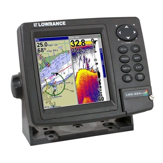
- Page 1 Pub. 988-0152-111 www.lowrance.com LMS-334c iGPS & LMS-339cDF iGPS Fish-finding Sonar & Mapping GPS Installation and Operation Instructions...
- Page 2 Copyright © 2006 Lowrance Electronics, Inc. No part of this manual may be copied, reproduced, republished, transmitted or distributed for any purpose, without prior written consent of Lowrance Electronics. Any unauthorized commercial distribution of this manual is strictly prohibited. Lowrance is a registered trademark of Lowrance Electronics, Inc.
-
Page 3: Table Of Contents
Section 1: Read Me First! ... 1 Capabilities and Specifications: ... 3 How to use this manual: typographical conventions ... 10 Arrow Keys ... 12 Keyboard ... 12 Menu Commands ... 12 Instructions = Menu Sequences ... 12 Section 2: Installation & Accessories... 13 Preparations... - Page 4 Navigation Page ... 45 Map Page... 45 SonarPage ... 46 Basic Sonar Quick Reference ... 49 Sonar Operations ... 50 Fish Symbols vs. Full Sonar Chart ... 52 Other Free Training Aids ... 53 Section 4: Sonar Options & Features... 55 ASP...
- Page 5 Map With Sonar Split Screen... 84 Sonar Simulator... 84 Stop Chart ... 86 Surface Clarity ... 87 Transparency ... 88 Upper and Lower Limits ... 89 Zoom & Zoom Bar ... 89 Zoom Pan... 89 Section 5: Sonar Troubleshooting ... 91 Section 6:Basic GPS Operations ...
- Page 6 Create Icon at Current Position ... 128 Delete an Icon ... 128 Navigate to an Icon ... 129 Routes... 129 Create and Save a Route ... 130 Delete a Route ... 132 Edit a Route Name... 132 Edit Route Waypoints... 133 Navigate a Route...
- Page 7 Pop-up Map Information ... 152 Map Boundaries ... 152 Fill Water With White ... 152 Map Overlays (Range Rings; Lat/Long Grid) ... 152 Map Datum Selection ... 153 Map Detail Category Selection... 154 Map Orientation ... 154 NauticPath USA Marine Charts... 156 Nautical Chart Notes...
- Page 8 A CAREFUL NAVIGATOR NEVER RELIES ON ONLY ONE METHOD TO OBTAIN POSITION INFORMATION. When showing navigation data to a position (waypoint), a GPS unit will show the shortest, most direct path to the waypoint. It provides navigation data to the waypoint regardless of obstructions.
-
Page 9: Section 1: Read Me First
GPS receiver. First, we want to thank you for buying a Lowrance sonar/GPS unit. Whether you're a first time user or a professional fisherman, you'll dis- cover that your unit is easy to use, yet capable of handling demanding navigation and sonar tasks. - Page 10 After you've gained some experience with your sonar, you'll want to check out Section 4, which discusses more advanced Sonar Options and Other Features. When you come to a sonar menu command on your unit’s screen, you can look it up in the manual by skimming over the table of contents, just flip- ping through Section 3 or scanning through the sonar options in Section 4.
-
Page 11: Capabilities And Specifications
tains. It's important to us (and our power users), but, if you don't care how many watts of power the unit has, or how many waypoints the your unit can store, skip ahead to important information on how the sonar works, on page 5. - Page 12 Transmitter: ... LMS-339cDF: 4,000 watts peak-to-peak/500 Depth capability:... LMS-339cDF: 2,500 feet/762 meters. Depth display:... Continuous display. Graph recording:... Up to 2 GB on one MMC (or SD) card Audible alarms: ... Deep/shallow/fish/zone. Automatic ranging:... Yes, with instant screen updates. Auto bottom track:... Yes Zoom bottom track: ...
-
Page 13: How Lowrance Sonar Works
Custom mapping: ... MapCreate Mapping memory:...Up to 2 GB on one MMC (or SD) card. Position updates: ... Every second. Position points: ... 1,000 waypoints; 1,000 event marker icons. Audible alarms: ... Arrival/off-course/anchor. Graphic symbols for waypoints or event marker icons: ... 42. Routes:... -
Page 14: How Lowrance Gps Works
(Lowrance developed the world's first transistorized sportfishing sonar in 1957.) A sonar consists of a transmitter, transducer, receiver and display. In simple terms, here's how it finds the bottom, or the fish: The transmitter emits an electrical impulse, which the transducer con- verts into a sound wave and sends into the water. - Page 15 'em and record new ones, over and over again. These GPS Data Files (file format *.usr) can be shared between, not only the LMS-334c iGPS and LMS-339cDF iGPS, but other Lowrance GPS units and even personal computers.
-
Page 16: Introduction To Gps And Waas
These MapCreate custom maps contain much greater de- tail than the basic background map. These Custom Map Files (file format *.lcm) not only may be shared between the LMS-334c iGPS and 339cDF iGPS, but also with other Lowrance GPS and sonar/GPS units as well as personal computers. - Page 17 Three of these satellites are spares, unused until needed. The rest vir- tually guarantee that at least four satellites are in view nearly any- where on Earth at all times. The system requires signal reception from three satellites in order to determine a position. This is called a 2D fix. It takes four satellites to determine both position and elevation (your height above sea level —...
-
Page 18: Free Training Aids Available
WAAS signal from ground receivers. You'll find that using your GPS receiver is both easy and amazingly accurate. It’s easily the most accurate method of electronic navigation available to the general public today. Remember, however, that this receiver is only a tool. - Page 19 Sonar Viewer You can also download a free copy of our Sonar Viewer software. This PC-based software application plays back any sonar chart log recorded with a Lowrance sonar product. Features include: • Adjustable range, zoom, sensitivity, ColorLine, noise rejection, surface clarity, etc.
-
Page 20: Arrow Keys
Arrow Keys The arrow keys control the movement of dotted cross-hair lines on your mapping screen called the cursor. The arrow keys also control a hori- zontal line depth cursor on the sonar screen. The arrow keys help you move around the menus so you can execute different commands. They are represented by symbols like these, which denote the down arrow key, the up arrow, the left arrow and the right arrow: ↓... -
Page 21: Section 2: Installation
Section 2: Installation Preparations You can install the unit in some other order if you prefer, but we rec- ommend this installation sequence: Caution: You should read over this entire installation section before drill- ing any holes in your vessel! 1. -
Page 22: Recommended Tools And Supplies
ducer does "kick-up," the bracket can easily be pushed back into place without tools. Read these instructions carefully before attempting the installation. Determine which of the installation methods is right for your boat. Use extreme care if mounting the transducer inside the hull, because once the epoxy is applied and it is set into position, the transducer cannot be removed. - Page 23 water, interference caused by bubbles and turbulence will show on the sonar's display in the form of random lines or dots whenever the boat is moving. NOTE: Some aluminum boats with strakes or ribs on the outside of the hull create large amounts of turbulence at high speed. These boats typically have large outboard motors capable of propelling the boat at speeds faster than 35 mph.
-
Page 24: How Low Should You Go
Transom Hull bottom Align transducer centerline with hull bottom. A dual frequency transducer (left) and a single frequency transducer (right). How low should you go? For most situations, you should install your Skimmer transducer so that its centerline is level with the bottom of the boat hull. This will usually give you the best combination of smooth water flow and protec- tion from bangs and bumps. -
Page 25: Transom Transducer Assembly And Mounting
knocked off when docking or loading on a trailer. The shoot-thru-hull installation does have its drawbacks. First, some loss of sensitivity does occur, even on the best hulls. This varies from hull to hull, even from different installations on the same hull. This is caused by differences in hull lay-up and construction. - Page 26 Align plastic ratchets in bracket. B. Two-piece bracket: Locate the four plastic ratchets in the trans- ducer's hardware package. Press two ratchets into the sides of the plastic bracket and two on either side of the transducer as shown in the following illustrations.
- Page 27 2. Aligning the transducer on the transom. A. One-piece bracket: Slide the transducer between the two ratch- ets. Temporarily slide the bolt though the transducer assembly and hold it against the transom. Looking at the transducer from the side, check to see if it will adjust so that its face is parallel to the ground. If it does, then the "A"...
- Page 28 If the transducer's face isn't parallel with the ground, remove and disassemble the transducer and ratchets. Place the ratchets into the bracket holes with the letter "B" aligned with the bracket alignment mark. Place them on the transducer aligned with the 12 o'clock posi- tion on the transducer stem.
- Page 29 Transom Transom Position transducer mount on transom and mark mounting holes. Side view shown (left) and seen from above (right). 5. Attaching transducer to transom. A. One-piece bracket: Remove the transducer from the bracket and re-assemble it with the cable passing through the bracket over the bolt as shown in the following figures.
-
Page 30: Trolling Motor Bracket Installation (Single-Frequency Only)
6. Route the transducer cable through or over the transom to the so- nar unit. Make sure to leave some slack in the cable at the transducer. If possible, route the transducer cable away from other wiring on the boat. Electrical noise from the engine's wiring, bilge pumps, VHF radio wires and cables, and aerators can be picked up by the sonar. -
Page 31: Transducer Orientation And Fish Arches
3. Route the transducer cable alongside the trolling motor shaft. Use plastic ties (not included) to attach the transducer cable to the troll- ing motor shaft. Make sure there is enough slack in the cable for the motor to turn freely. Route the cable to the sonar unit and the trans- ducer is ready for use. -
Page 32: Shoot-Thru-Hull Preparation
NOTE: Periodically wash the transducer's face with soap and water to re- move any oil film. Oil and dirt on the face will reduce the sensitivity or may even prevent operation. Shoot-Thru-Hull Preparation Hulls With Flotation Materials The transducer installation inside a fiberglass hull must be in an area that does not have air bubbles in the resin or separated fiberglass lay- ers. - Page 33 Transducer location (high speed) Shoot-thru-hull transducer locations for high speed or trolling speed operation. To choose the proper location for shoot-thru-hull mounting, follow these testing procedures: (You may need a helper to complete these steps.) 1. Anchor the boat in about 30 feet of water. Add a little water to the sump of the boat.
-
Page 34: Shoot-Thru-Hull Installation
3. Now move the transducer around to find the best location with the strongest possible bottom signal. If you find a spot with an acceptable bottom signal, mark the location and move on to step 4. If you can't get an acceptable bottom signal, try turning up the sensi- tivity by three or five keystrokes and then move the transducer around once more. - Page 35 Sand this surface (unit's face) Orient the Skimmer with the nose facing the bow of the boat. WARNING: Use only the epoxy available from LEI. It has been for- mulated to work with these installation procedures. Other epoxy types may be too thin or may not cure to the right consistency for optimum transducer performance.
-
Page 36: Speed/Temperature Sensors
Speed/Temperature Sensors Optional Speed Sensor Installation All the units in this series can display speed and distance traveled, but only the LMS-339cDF iGPS comes packed with a speed sensor. If you want to purchase an optional additional sensor for your unit, refer to the accessory ordering information inside the back cover of this man- ual. -
Page 37: Power Connections
Transom Speed sensor mounting configuration: side view (left) and rear view (right.) If the base of the transom has a radius, fill the gap between the tran- som and the sensor with the sealant compound. This will help ensure a smooth water flow. -
Page 38: Powering A Nmea 2000 Buss
To unit The Power/Data cable for this unit. Caution All of the wires in the power/data cable have bare ends for eas- ier installation. The bare ends on any unused wires could cause an electrical short if left exposed. To prevent this, you should cover the individual wire ends –... - Page 39 Powering the Unit (Power Supply cable – red and black wires) The unit works from a 12-volt battery system. For the best results, at- tach the unit power cable directly to the battery. You can attach the power cable to an accessory or power buss, but you may have problems with electrical interference.
-
Page 40: Gps Internal Antenna
Data Cable Power connections for LMS-334c iGPS and LMS-339cDF iGPS units. NOTE: If you are powering a NMEA 2000 buss, you will attach both the NMEA 2000 Power cable and the unit's Power Supply cable to an electric power source. -
Page 41: Connecting To A Nmea 2000 Network
(See instructions in this section on powering a NMEA 2000 buss.) IMPORTANT NOTE: The data from your internal GPS receiver will not be trans- mitted across the LowranceNET NMEA 2000 network. You must have an LGC-2000 GPS antenna module in the network for that to happen. - Page 42 Orange (Receive) Com-1 Shield (Ground) To unit Com-1 wiring to receive NMEA position information from some other GPS receiver. Yellow (Transmit) Com-1 Shield (Ground) To unit Com-1 wiring to transmit NMEA position information to another NMEA-compatible device. NMEA Transmit Ground...
-
Page 43: Mounting The Unit: Bracket Or Portable
Sonar socket Optional speed sensor Transducer LMS-334c iGPS and LMS-339cDF iGPS cable connections. Mounting the Unit: Bracket or Portable You can install the sonar unit on the top of a dash with the supplied gimbal bracket. It can also be mounted on a portable power supply. - Page 44 Optional R-A-M mounting system. Bracket Installation Mount the unit in a convenient location, provided there is clearance behind the unit when it's tilted for the best viewing angle. This must be a location with a clear view of the sky, so the internal GPS antenna can lock-on to satellite signals.
- Page 45 Drill a 1-inch (25.4 mm) hole in the dash for the power and transducer cables. The best location for this hole is immediately under the gimbal bracket location. This way, the bracket can be installed so that it covers the hole, holds the cables in position and results in a neat installation. Some customers prefer to mount the bracket to the side of the cable hole.
-
Page 46: Mmc Or Sd Card Memory Card Installation
Portable Installation Like many Lowrance products, this unit is capable of portable operation by using an optional portable power pack (PPP). The power pack and an optional portable transducer expand the uses for your sonar unit. The PPP makes it easy to use the unit on your boat or take it to the dock, on an ice fishing trip or use it as a second sonar in a friend's boat. -
Page 47: Other Accessories
The MMC slot is located in a compartment on the front of the case. The compartment door is located at the lower right corner. The following figure shows a close-up with the door opened. Thumb Insert card face up, screw this way Memory card compartment with a 16 MB MMC card installed. -
Page 48: Face Cover
MapCreate™ 6 CD-ROM (left). MMC card reader for USB ports (right). Face Cover A white protective cover that snaps on and off the front of the unit is available. This cover is intended for use when the vehicle is idle. WARNING: When the unit is mounted in an unprotected area, such as an open boat cockpit, the protective face cover must... -
Page 49: Section 3: Basic Sonar Operation
Section 3: Basic Sonar Operation This section addresses the unit's basic sonar operations. The instruc- tions in Sec. 3 are in chronological order. Sec. 4, Sonar Options & Other Features, will discuss more advanced functions and utilities. Before you turn on the sonar unit, it is a good idea to learn about the different keys, the Main Menu, the four Page screens and how they all work together. -
Page 50: Power/Lights On And Off
4. ARROW KEYS – The arrow keys are used to navigate through menus, make menu selections, enter data and move around the map. 5. ENT/ICONS – The Enter key allows you to save data, accept values, execute menu commands and create event marker icons. 6. - Page 51 Cancel Navigation: turns off the various navigation commands. Used to stop navigating after you have reached your destination. Sonar Setup: sets sonar options. GPS Setup: sets GPS receiver options. System Setup: sets general configuration options. Sun/Moon Calculations: finds the rising and setting time of the sun and the moon.
-
Page 52: Satellite Status Page
Pages Menu showing Sonar display options. Satellite Status Page The Satellite Status Page provides detailed information on the status of the unit's satellite lock-on and position acquisition. To get to the Satel- lite Status Page: Press the This page represents a GPS function, so it is discussed in much greater detail in Sec. -
Page 53: Navigation Page
Navigation Page This screen has a compass rose that not only shows your direction of travel, but also the direction to a recalled waypoint. To get to the Navi- |← → to gation Page, press PAGES EXIT AVIGATION This page represents a GPS function, but also has a navigation with sonar option, which will keep you updated on what is under your boat as well as where you are going. -
Page 54: Sonarpage
Map Page is also the default screen that appears when you turn on the |← → to unit. To get to the Map Page from another page, press PAGES EXIT You can display a split screen showing both the Map and Sonar pages at the same time. - Page 55 Sonar display options (from left) Split Zoom and Split Frequency. Sonar chart display options (from left) Digital Data and Flasher. Sonar Page Menu.
- Page 56 Digital data overlay (depth & temperature) Fish arches Structure Sonar Page in full sonar chart mode. You can customize how the Sonar Page displays its pictures and other data in many ways. We'll discuss all of those features and options in Sec. 4, but to show you how easy this unit is to operate, the following page contains a 10-step quick reference that will cover most fish finding situations.
-
Page 57: Basic Sonar Quick Reference
Basic Sonar Quick Reference 1. Mount the transducer, antenna and unit. Connect the unit to electric power and the transducer. (If GPS operation is desired, connect GPS antenna, too.) Make sure the MMC is in. (See complete installation de- tails beginning on page 13.) 2. -
Page 58: Sonar Operations
Sonar Operations As you can see from the quick reference on the previous page, basic operation is pretty easy, right out of the box. If you are a sonar novice, try operating the unit with the factory defaults until you get a feel for how it's working. As you are learning the basics, there is one setting you might want to tinker with from time to time —... - Page 59 You can change the sensitivity level whether you are in Auto Sensitivity mode or Manual Sensitivity mode. The adjustment method works the same in both modes, but it gives you slightly different results. Adjusting sensitivity in Auto Sensitivity Mode is similar to manually ad- justing a car's speed with the accelerator pedal while cruise control is on.
-
Page 60: Fish Symbols Vs. Full Sonar Chart
NOTE: If you want to change the sensitivity in Manual Mode, turn off Auto Sensitivity. From the Sonar Page, press |↑ to TIVITY tivity setting. When it's set at the desired level, press Important Tip: While you are experimenting with settings, it is possible to scram- ble them so the sonar picture disappears from your screen. -
Page 61: Other Free Training Aids
Other Free Training Aids The sonar options section discusses Fish I.D., fish alarms and other features in greater detail. If you or a friend has Internet access, you can also learn more about interpreting what you see on your sonar screen. Visit our web site, www.lowrance.com. - Page 62 Notes...
-
Page 63: Section 4: Sonar Options & Features
Section 4: Sonar Options & Features ASP (Advanced Signal Processing) The ASP feature is a noise rejection system built into the sonar unit that constantly evaluates the effects of boat speed, water conditions and interference. This automatic feature gives you the best display pos- sible under most conditions. -
Page 64: Alarms
Alarms This unit has three different types alarms, Sonar, GPS and NMEA 2000. There are three Sonar alarms: Fish Alarm, Zone Alarm and Depth Alarm. The Fish Alarm will sound when the Fish I.D. feature determines an echo is a fish. The Zone Alarm consists of a blue bar on the side of the screen. -
Page 65: Zone Alarm
4. Press ← to HALLOW back to the main page display. To adjust and turn on the deep alarm: 1. Press MENU MENU 2. Press ↓ → to 3. Press ↑ ↓ to change the first number, then press to the next number and repeat until the depth is correct, then press 4. -
Page 66: Fish Alarm
Fish Alarm Use fish alarm to receive an audible alarm when fish or other objects are detected by the Fish I.D. feature (Fish I.D. must be turned on for the Fish Alarm to work). A different tone sounds for each fish symbol size shown on the display. -
Page 67: Calibrate Speed
3. To enable the Empty Alarm, highlight the to turn on (check) the alarm. Press → to the Percent box and press . Use the ↑ ↓ keys to select the first number, then press and press → to move to the next number. When the desired percentage has been entered, press You do not have to set both the Full and Empty alarms. -
Page 68: Colorline
through the sonar signal cone, the image appears on the screen as a long line instead of a fish arch. Reducing the chart speed may result in a shorter line that more closely resembles a regular fish return. Sonar Page menu with Chart Speed command selected (left). Chart Speed Control Bar (right). -
Page 69: Depth Cursor
Sonar Page menu with ColorLine command selected (left). The ColorLine control bar (right). To adjust the ColorLine level: 1. From the Sonar Page, press 2. The ColorLine Control Bar appears. Press ↑ ↓ to adjust Colorline. 3. When it's set at the desired level, press Thin or no ColorLine A small amount of ColorLine indicates a soft bottom, probably sand or mud (left). -
Page 70: Depth Range - Automatic
Cursor line Depth box Sonar Page menu with Depth Cursor selected (left). Sonar chart with active depth cursor (right). The cursor is set at 34.64 feet deep. The cursor can be moved to any location on the screen, letting you pin- point the depth of a target. -
Page 71: Depth Range - Manual
1. From the Sonar Page, press 2. The Depth Range Control Scale appears. Press ↑ ↓ to select a differ- ent depth range. A blue bar highlights the selected range. The shaded numbers cannot be selected. 3. When the new range is selected, press Depth Range - Manual You have complete control over the range when the unit is in the man- ual mode. - Page 72 Sonar Page Menu with Upper and Lower Limits command selected (left). Sonar Chart Limits menu with Upper Limit selected (right). To change the upper and lower limits: 1. From the Sonar Page, press |↓ to MENU PPER OWER IMITS The Sonar Chart Limits menu appears, with Upper Limit selected. .
-
Page 73: Fastrack
FasTrack This feature automatically converts all echoes to short horizontal lines on the display's far right side. The graph on the rest of the screen con- tinues to operate normally. FasTrack gives you a rapid update of condi- tions directly under the boat. This makes it useful for ice fishing or when you are fishing at anchor. -
Page 74: Fishtrack
Does that mean Fish I.D. is broken? No — the feature is interpreting sonar returns in a specific way to help take some of the work out of reading the screen. Remember: Fish I.D. is one of the many tools we provide so you can analyze your sonar returns for maximum fish find- ing information. - Page 75 Fig. 1 A Fig. 1 B Many fish Fewer fish arches visible symbols visible Fig. 2 A Fig. 2 B Fish arches No fish shown above structure FasTrack graph confirms fish above structure Figures 1A and 2A (left) show Sonar Page in normal chart mode. Figures 1B and 2B (right) show the same underwater scene with Fish I.D.
-
Page 76: Frequency (Lms-339Cdf Only)
Symbols with FishTrack depths Sonar Features menu with Fish I.D. Depths selected (left). When the check box to the left is checked, the feature is on. Sonar Page with Fish I.D. symbols and FishTrack depths turned on (right). Frequency (LMS-339cDF only) The LMS-339cDF transducer can operate at both 200 kHz and 50 kHz. -
Page 77: Hyperscroll
Sonar Features menu with a frequency of 200 kHz selected. To change the frequency setting to 50 kHz: 1. From the Sonar Page, press 2. Press → ↓ to 3. Press EXIT EXIT To change the frequency setting to 200 kHz: 1. -
Page 78: Nmea 2000
Sonar Page menu with the Log Sonar Chart Data command selected (left). Sonar Chart Logging menu, with the Start Logging command selected (right). The menu says the MMC has 5.42 MB of free space, which will record the scrolling chart for 28 minutes and 44 seconds. To record or log chart data: 1. - Page 79 command. For example, if you left your watch at home, you could dis- play the local time on top of the map. Or, if you wanted to see details about your route and trip, you could show your bearing, course, average speed and trip distance.
- Page 80 Every Page display has a maximum number of items you can show us- ing the Overlay Data command. 5. After the desired changes are made, press page display. Ent to Add selected (left). Data Viewer menu (center). Select a category and press ENT.
- Page 81 NOTE You can also remove data directly from the Data Viewer menu by un- checking the data option you would like to remove. Overlay Data Shown, with Date option selected (left). Remove highlighted on Data information window (right). To move overlaid data: You may find it useful to rearrange data on the display window.
-
Page 82: Ping Speed & Hyperscroll
Depth selected in the overlay data shown menu (left). By pressing ← → the size of the Depth display will increase or decrease on the display. The size of the Depth text has been changed to enormous (right). To change displayed data font size: 1. - Page 83 When using HyperScroll, you may also need to manually decrease the sensitivity for optimum performance. Depending on water depth and other conditions, HyperScroll may cause a second bottom echo to return to the transducer during the next ping cycle, or sounding. This can result in a large amount of clutter appearing on the screen.
-
Page 84: Reset Options
Reset Options This command is used to reset all features, options and settings to their default settings. This is useful when you have changed several settings and want to return the unit to basic automatic operation. 1. Press MENU MENU 2. - Page 85 If the transducer is 1 foot below the surface, and the screen shows the water depth as 30 feet, then the actual depth is 31 feet. On sailboats or other large vessels with deep drafts, the distance be- tween the transducer installation and the keel or lower engine unit can be several feet.
-
Page 86: Sensitivity & Auto Sensitivity
Sensitivity & Auto Sensitivity The sensitivity controls the ability of the unit to pick up echoes. Sensi- tivity can be adjusted, because water conditions vary greatly. A low sensitivity level (from zero to 50 percent) excludes much of the bottom information, fish signals, and other target information. -
Page 87: Sonar Chart Mode
Sensitivity selected (left). The Sensitivity Control Bar (right). To adjust sensitivity in manual mode: 1. First, turn off Auto Sensitivity: from the Sonar Page, press ENSITIVITY 2. Press ↑ to ENSITIVITY Press ↓ ↑ to pick a different sensitivity setting. When it's set at the de- sired level, press EXIT NOTE:... -
Page 88: Full Sonar Chart
Pages Menu showing sonar chart display options. Full Sonar Chart This is the default mode used when the unit is turned on for the first time or when it's reset to the factory defaults. The bottom signal scrolls across the screen from right to left. Depth scales on the right side of the screen aid in determining the depth of targets. -
Page 89: Split Zoom Sonar Chart
Split Zoom Sonar Chart A split chart shows the underwater world from the surface to the bot- tom on the right side of the screen. The left side shows an enlarged ver- sion of the right side. The zoom range shows in the bottom left corner. Split Zoom Sonar Chart. -
Page 90: Digital Data/Chart
3. The Sensitivity Control Bar appears. Press ↓ ↑ to adjust sensitivity. When it's set at the desired level, press EXIT Digital Data/Chart This mode shows the chart on the right side of the screen. The left side has five digital data boxes containing: Water Depth; Water Speed (from an op- tional speed sensor);... -
Page 91: Flasher
Customize highlighted (left). GPS Data and Navigation categories ex- panded in Data Viewer menu (right). Selecting the category name and pressing will open the category, showing its data options. An open category (one with a "–" next to its name) can be collapsed to hide its contents. Just select the category name and press Open any categories that might contain data you want to display. -
Page 92: Map With Sonar Split Screen
line feature to show weaker targets as lighter colors. The bottom depth is also shown as a black bar across the outer circle. Map With Sonar Split Screen There is a page mode that splits the screen in half, with the map on the left and the sonar on the right. - Page 93 NOTE: With Simulate Position checked, the simulator will automatically run the GPS simulator. 2. To use the default sonar chart log stored in the unit, press The recorded chart begins scrolling across the screen, just as if you were on the water. 3.
-
Page 94: Stop Chart
1. Press MENU 2. Press ↓ ↑ to file name| Select Browse MMC Files from the Main Menu. NOTE: If you turn on your unit before attaching a transducer, it may enter a demo mode. The words "demo mode" flash on the bottom of the screen and a sonar chart plays much like the simulator. -
Page 95: Surface Clarity
Sonar Menu with Stop Chart command selected. The box is unchecked, indicating the chart is scrolling across the screen. Surface Clarity The markings extending downward from the zero line on the chart are called surface clutter. These markings are caused by wave action, boat wakes, temperature inversion and more. -
Page 96: Transparency
To adjust the Surface Clarity level: 1. From the Sonar Page, press |↓ to MENU ONAR EATURES 2. Press ↓ to ENT. URFACE LARITY ↓ ↑ to select clarity level, then press repeatedly. 3. Press EXIT Surface clutter In the illustration (left) Surface Clarity is turned off. The view shows Surface Clarity set at High (right). -
Page 97: Upper And Lower Limits
To adjust Menu Transparency level: Press |↓ to . The slider bar MENU MENU RANSPARENCY RANSPARENCY appears. Press ↑ ↓ to adjust Transparency. Upper and Lower Limits See the entry in this section for Depth Range — Upper and Lower Limits. - Page 98 Notes...
-
Page 99: Section 5: Sonar Troubleshooting
Section 5: Sonar Troubleshooting If your unit is not working, or if you need technical help, please use the following troubleshooting section before contacting the customer service department. It may save you the trouble of returning your unit for re- pair. - Page 100 3. The water may be deeper than the sonar's ability to find the bottom. If the sonar can't find the bottom signal while it's in the automatic mode, the digital sonar display will flash continuously. It may change the range to limits far greater than the water you are in. If this hap- pens, place the unit in the manual mode, then change the range to a realistic one, (for example, 0-100 feet) and increase the sensitivity.
- Page 101 To eliminate or minimize the effects of electrical noise, first try to de- termine the cause. With the boat at rest in the water, the first thing you should do is turn all electrical equipment on the boat off. Make sure the engine is also off.
- Page 102 Notes...
-
Page 103: Section 6: Basic Gps Operations
Section 6: Basic GPS Operations This section addresses the unit's most basic GPS operations. The tuto- rials presented in Sec. 6 follow a chronological order. Sec. 7, Advanced GPS Operations, will discuss other more advanced functions and utili- ties. Material in Sec. 7 is arranged in alphabetical order. Before you turn on the unit and find where you are, it's a good idea to learn about the different keys, the four Page screens and how they all work together. -
Page 104: Power/Lights On And Off
4. ARROW KEYS – The arrow keys are used to navigate through the menus, make menu selections, move the map cursor and sonar chart cursor and enter data. 5. ENT/ICONS – The Enter key allows you to save data, accept values and execute commands. - Page 105 Cancel Navigation: turns off the various navigation commands. Used to stop navigating after you have reached your destination. Sonar Setup: sets various sonar options. GPS Setup: sets various GPS receiver options. System Setup: sets general configuration options. Sun/Moon Calculations: finds the rising and setting time of the sun and the moon.
-
Page 106: Sonar Page
Pages Menu showing Map display options. Sonar Page The Sonar Page displays the sonar chart, a view of the water column from the surface to the bottom. The chart scrolls across the screen from right to left, displaying signal echoes that represent fish, structure and the bottom. - Page 107 You can use this to see which satellites are obstructed by obstacles in your immediate area if the unit is facing north. The GPS receiver is tracking satellites that are in bold type. The re- ceiver hasn't locked onto a satellite if the number is grayed out, there- fore it isn't being used to solve the position.
-
Page 108: Navigation Page
Navigation Page This screen has a compass rose that not only shows your direction of travel, but also the direction to a recalled waypoint. The page has two options, navigation with digital data and navigation with sonar. To get to the Navigation Page, press to select one of the two menu items. - Page 109 When navigating to a waypoint, your ground speed, track, distance, bearing to the waypoint and course are all displayed. NOTE: Remember: when Speed, Track and Position information displays are flashing, satellite lock has not been achieved and no position fix has been determined.
- Page 110 Left cross track error line Current track or heading, shown in degrees Compass bearing to destination Trail line Navigation information displays in data boxes Navigation Page going to a waypoint. The cross track error range is shown on the compass rose as a wide, white, corridor enclosing the course line.
-
Page 111: Map Page
various options. (Options and setup are discussed in Sec. 8). To access the Navigation Page Menu, from the Navigation Page, press Map Page The Map Page screens show your course and track from a bird's-eye view. By default, this unit shows the map with north always at the top of the screen. -
Page 112: Background Map Vs. Mapcreate Map Content
more map content (except for a few major city streets.) Load your own high-detail custom map made with MapCreate (or a pre-made Free- domMap from LEI), and you can zoom in to 0.02 miles with massive amounts of accurate map detail. Map Pages with high-detail MapCreate map of an urban area loaded on the MMC. - Page 113 NOTE: Available through LEI Extras (look inside back cover for accessory ordering information), FreedomMaps are pre-made maps that con- tain all of the same information available in a custom MapCreate map, without any work on your part. Interstate Minor Streets Marker School POI Position,...
- Page 114 Digital Data map page (left). Two Position Formats page (right). In pages that have two major windows (such as two maps) you can tog- back forth between windows pressing . This allows you to change which map your cursor PAGES PAGES moves on, and which map the menu operates on.
- Page 115 You can switch between maps by pressing The map PAGES PAGES. that is active will have an Active Map indicator listed in a blue bar at the top of the active window. In Two Maps mode you can modify the windows to be side by side or stacked one on top of the.
-
Page 116: Basic Gps Quick Reference
Basic GPS Quick Reference Start outdoors, with a clear view of the open sky. As you practice, try navigating to a location at least a few blocks away. Navigation in too small an area will constantly trigger arrival alarms. 1. Connect the unit to electric power and the antenna module. Make sure the MMC is in. -
Page 117: Find Your Current Position
Find Your Current Position Finding your current position is as simple as turning the unit on. With- out obstruction from dense foilage, terrain or structures, the unit auto- matically searches for satellites and calculates its position in approxi- mately one minute or less. If for some reason satellite acquisition takes longer, you may be inside a structure or vehicle or in terrain that is blocking signal reception. -
Page 118: Selecting Map Item With The Cursor
Cursor line Selected airport The selected airport is 4.2 miles to the northwest. Selecting Map Item With the Cursor 1. Use the zoom keys and the arrow keys to move around the map and find the item you want to select. 2. - Page 119 After the unit has acquired a position: 1. Press |↓ to POI-R 2. You could search the entire restaurant category, but in this example we will narrow our search. Press → to |↓ to HAINS 3. The unit says it is calculating, then a list of restaurants appears, with the closest at the top of the list, and the farthest at the bottom of the list.
-
Page 120: Set A Waypoint
6. The unit's map appears, with the cross-hair cursor highlighting the restaurant' s POI symbol. A pop-up data box shows the POI's name, distance and bearing. A data box at the bottom of the screen continues to display the location's latitude and longitude. 7. - Page 121 Figure 1. Figure 3. Sequence for setting waypoint. Figure 1: press WPT twice to call up Find Waypoint screen (Figure 2) and set a waypoint. Figure 3: confir- mation message. Figure 4: Waypoint number and symbol are visible. NOTE: The Quick Save method uses a default waypoint symbol, unless you edit an existing waypoint and change its symbol.
-
Page 122: Navigate To A Waypoint
Create Waypoint by Entering a Position 1. Press , select 2. Press ↓ to NTERED 3. Press → to ATITUDE change the first character, then press → to the next character and re- peat until the latitude is correct. Press 4. -
Page 123: Set Man Overboard (Mob) Waypoint
Course line (dotted) Off course range, set at 0.20 mile Navigation Page, navigating toward waypoint 004. Set Man Overboard (MOB) Waypoint One of boating's most terrifying events is having a friend or family member fall overboard. It's particularly dangerous at night or if you're out of sight of land. -
Page 124: Navigate To Cursor Position On Map
Navigating to Man Overboard: Man Overboard Activated message (left). Navigation Page (center). Map Page (right). The victim is to the star- board of the vessel. The GPS shows which direction to go for the rescue. The man overboard position is also stored in the waypoint list for future reference. -
Page 125: Navigate To A Point Of Interest
Other features, such as a river or a street intersection will not appear highlighted, but the cursor will take you to those locations just the same. 3. Press MENU The Map Page will display a dotted line from your current position to the cursor position. - Page 126 On the screen, trails are represented by a solid line extending from the back of the current position arrow. The unit is set at the factory to automatically create and record a trail while the unit is turned on. The unit will continue recording the trail until the length reaches the maximum trail point setting (default is 2,000, but the unit can record trails 9,999 points long).
-
Page 127: Displaying A Saved Trail
New trail named Trail 2 is created when Trail 1 is set to inactive. New travel will be recorded in this trail, which is active and visible. Trails do not have to be visible in order to be active. You can save and recall up to 10 different plot trails, which can be cop- ied to your MMC for archiving or for transfer to your MapCreate soft- ware. -
Page 128: Navigating Trails
Navigating Trails There are three methods for following a trail: visual trailing, navigating a trail (forward) and backtracking a trail (backward). Try each method to see which you prefer. Visual trailing is the simplest method. It uses only the Map Page and requires no menu commands at all. - Page 129 5. Begin moving and let your unit guide you. 6. When you reach your destination, cancel navigation: press |↓ to . A confirmation message will MENU MENU ANCEL AVIGATION appear. Press ←| Figure 1. Figure 2. Figure 4. Figure 3. Navigate a trail menu sequence: Fig.
-
Page 130: Navigate A Back Trail
Present position arrow Trail point Navigate trail, map views: Driver is northbound heading straight to- ward trail point 6 (left). Northbound driver has reached point 6 and has turned west to follow trail (right). Track or compass heading indicator Trail waypoint symbol Course... -
Page 131: Transfer Custom Maps And Gps Data Files
6. When you reach your destination, be sure to cancel your navigation: press |↓ to . A confirmation message MENU MENU ANCEL AVIGATION will appear. Press ←| Transfer Custom Maps and GPS Data Files Custom Maps: Custom maps work only from the MMC card or SD card. When a card containing a Custom Map File is loaded into the unit, the unit auto- matically loads the map into memory when the unit is turned on. - Page 132 To transfer data from the unit to the MMC: press To transfer data from the MMC to the unit: press → to 3. Saving to MMC: To accept the default name "Data" for the GPS Data File, press ↓ to shown in the following figures), press Press ↑...
-
Page 133: Cancel Navigation
Figure 1. Figure 2. Figure 3. Figure 4. These figures show the menu sequence for loading a GPS Data File from an MMC into the unit's memory. Cancel Navigation You can turn off any of the navigation commands after you reach your destination or at any other time by using the Cancel Navigation com- ←... - Page 134 Notes...
-
Page 135: Section 7: Advanced Gps Operations
Section 7: Advanced GPS Operations Find Distance from Current Position to Another Location 1. While on the Map Page press: 2. Center your cursor over the position you want to find the distance to. A rubber band line appears, connecting your current position to the cursor's location. -
Page 136: Create Icon On Map
called later for navigation purposes. These are sometimes referred to as event marker icons. This unit has 42 different symbols you can pick from when creating an icon. Icons are similar to waypoints, but they do not store as much informa- tion (like names) as waypoints do. -
Page 137: Navigate To An Icon
The Delete All Icons command will ask if you are sure. Press ← to . All icons will be deleted from the map. The Delete by Symbol command will launch the Select Symbol menu. Press ↑ ↓, ← → to select the icon symbol to delete, then press message appears letting you know all icons with the selected symbol have been deleted. -
Page 138: Create And Save A Route
waypoint. Once programmed into the GPS unit, a route provides the option of navigating forward through the route waypoints or in reverse order (you can even begin navigating in the middle of a route!) Create and Save a Route You have the option of creating and editing a route in the unit, or you can make a route on your computer with our MapCreate 6 software. - Page 139 Edit Route menu (left). Edit Route Waypoints menu (right) with Add From Map command selected. 3. Use the Zoom keys and arrow keys to move the map and cursor until the cursor is centered on the spot where you want your route to begin. If you are starting at your current position or the current cursor posi- tion, you are already at the starting spot.
-
Page 140: Delete A Route
Route creation sequence, continued: Fig. 4. Point (3) set at on-ramp turn. Fig. 5. Waypoint (4) set at highway exit to frontage road leading to river. Waypoint (5) ends the route. Fig. 6. 5. Move the cursor to the next point in the route, a spot where you need to turn or change direction and press 6. -
Page 141: Edit Route Waypoints
3. Press ↑ ↓ to change the first character, then press → to move the cursor to the next character and repeat until the name is correct and press . Return to the main page display pressing Edit Route Waypoints You can edit the route by adding and removing waypoints. -
Page 142: Navigate A Route In Reverse
Route Planning on Main Menu (left). Routes menu (center). Edit Route menu (right). Navigate command is selected in the Action box. 2. Press ↓ to select route name| 3. Upon arrival at your destination, cancel navigation: press |↓ to MENU MENU The following figures show what the Navigation Page and Map Page look like while navigating a route. -
Page 143: Trails
Figure 1. Figure 3. Navigating along a route: Fig. 1 shows the Navigation Page at the start of a route, heading straight for the first waypoint (Wpt 1). In Fig. 2, the traveler has arrived at Wpt 1; the arrival alarm has been triggered and the bearing arrow now points toward Wpt 2. -
Page 144: Edit A Trail Color
to the next character and repeat until the name is correct. Press Press repeatedly to return to the main page display. EXIT Tip: You can quickly call up the Edit Trail menu by selecting a trail on the map with the cursor. Move the cursor over a trail and a pop-up box appears. -
Page 145: Utilities
Edit Trail Menu with Pattern option selected (left). Edited trail with Utilities Utilities are useful tools for traveling or for outdoor activities. Alarm Clock To get to the alarm clock menu: press LARM LOCK Sun/Moon Rise & Set Calculator To get to the Sun/Moon menu: press ALCULATIONS Trip Calculator To get to the Calculator menu: press... -
Page 146: Edit A Waypoint
To delete a waypoint from the map: 1. Use the arrow keys to select the waypoint with the cursor. 2. Press |↓ to main page display press To delete all waypoints at one time: press |↓ to ETUP ELETE to the main page display, press Edit a Waypoint Waypoint Name To edit waypoint name:... -
Page 147: Set A Waypoint By Average Position
Set a Waypoint by Average Position This feature sets a waypoint at the current position after taking several position readings and averaging them. This boosts waypoint position accuracy by helping to eliminate errors caused by atmospheric condi- tions and other factors. 1. - Page 148 Notes...
-
Page 149: Section 8: System & Gps Options
Section 8: System & GPS Options Alarms This unit has several GPS alarms. By default, all the alarms are turned on with the exception of the anchor alarm. You can turn the alarms off and on and change their distance settings. You can set an arrival alarm to flash a warning message and sound a tone when you cross a preset distance from a waypoint. -
Page 150: Nmea 2000 Alarm
IMPORTANT ALARM NOTES Anchor Alarm - The anchor alarm may be triggered even when you're sitting still. This can happen when using a small (less than .05 mile) anchor alarm range. Arrival Alarm - If you set the arrival alarm's distance to a small number and you run a route (see the Navigate Routes segment), this unit may not show navigation data to the next waypoint, once you arrive at the first one. -
Page 151: Auto Satellite Search
Full and Empty alarms or activate them individually. Auto Satellite Search To lock on to the satellites, the GPS receiver needs to know its current position, UTC time and date. Altitude is also used in the equation, but it's rarely required to determine a position. It needs this data so it can calculate which satellites should be in view. -
Page 152: Check Mmc Files And Storage Space
MMC File Browser. Check MMC Files and Storage Space To check MMC Files: Press |↓ to MENU MENU ROWSE ILES Communications Port Configuration The unit has one NMEA 0183 version 2.0 compatible communication port. The Com Port Menu, accessed from the System Setup Menu, al- lows you to configure the communications port to send or receive data from another electronic device, like autopilot. -
Page 153: Configure Nmea
For assistance in configuring the unit to communicate with another device, consult the factory. Customer service phone numbers are in the back of this manual. Configure NMEA You can configure the unit to use specific NMEA sentences. 1. Press MENU MENU 2. - Page 154 British, Irish, Finnish, German, New Zealand, Swedish, Swiss, Taiwan, and Greek grid systems are the national coordinate system used only in their respective countries. In order to use these grid systems, you must be in the respective country. This unit will pick the matching datum for you when you select the grid.
-
Page 155: Map Fix
Map Fix Map Fix is used with charts or maps. This system asks for a reference position in latitude/longitude, which you take from a marked location on the map. It shows the present position as distance on the map from that reference point. -
Page 156: Customize Page Displays
Configure a map fix so the unit can find a position on a printed map. Press → to ELECT Select the waypoint you saved the reference point under and press The unit displays a waypoint information screen with the command selected. -
Page 157: Gps Simulator
Customize Menu with GPS Data and Navigation categories opened. Selecting the category name and pressing contents, so you can choose items within it. An open category can be closed, by highlighting the category name and pressing Open any categories that might contain data you want to display. Then press ↓... - Page 158 The GPS Simulator menu. Adjust the settings to your preferences, then turn on the simulator by highlighting the box and pressing . Press GPS S EXIT IMULATOR peatedly to close the menu. A message and tone appear periodically, warning you the simulator is on. To turn off the simulator, repeat the steps above or turn off the unit.
-
Page 159: Hide Gps Features
Tip: You can pick any spot on the map to begin your simulation by using the Initialize GPS command. See its entry following the entry for Hide GPS Features. Hide GPS Features The GPS menus and features can be hidden from view with the Hide GPS Features command. -
Page 160: Show Map Data
You can also turn on or off Map Overlays, which display range rings and latitude and longitude grid lines. This menu also lets you activate Navionics Maps. To get to the Map Data menu, press Map Menu (left). Map Data Menu (right). Show Map Data From the Map Page, press ARTH... -
Page 161: Map Datum Selection
ring diameters are based on the current zoom range. For example: at the 100 mile zoom, the screen will show two rings with your current position in the center. The large ring touching the left and right sides of the screen is 100 miles in diameter (same as the zoom range). -
Page 162: Map Detail Category Selection
The Map Datum Menu. Map Detail Category Selection This menu determines which of the mapping features are shown on the screen. This includes, waypoints, trails, icons, cities and highways, etc. You can turn on or off any of these items to customize the map. To get to Map Categories: 1. - Page 163 In Track Up mode, map shows "N" and arrow to indicate north. Map orientation (left) is shown in north up and track up (right). This is fine if you're always traveling due north. What you see to your left corresponds to the left side of the map, to your right is shown on the right side of the map, and so on.
-
Page 164: Nauticpath Usa Marine Charts
NOTE In North Up and Course Up, the present position arrow appears in the center of the map page. In Track Up, the position arrow appears centered in the lower third of the page. NauticPath USA Marine Charts Your unit can display NauticPath electronic charts on MMCs. They work just like a MapCreate custom map on a MMC. -
Page 165: Port Information
Entrance to Aransas Pass on a NauticPath chart with 8-nautical mile zoom (left). Remaining images (left to right): same position at 4- nautical mile, 1-nautical mile and 0.3- nautical mile zoom ranges. Port Information NauticPath charts contain Port Services information, represented by anchor icons on the map display. -
Page 166: Tidal Current Information
Port Services information. Tidal Current Information NauticPath charts contain Tidal Current information, represented at large zoom ranges by a box icon with the letter "C." These icons will appear when you are zoomed in to a 6-mile range. The icon stands for a Tidal Current Sta- tion location. - Page 167 Cursor lines NauticPath chart showing Tidal Current Station icon selected by cur- sor (left). Tidal Current animated icon at .8-nautical mile range. Current Time Line Velocity Scale The Tidal Current Information screen displays daily tidal current data for this station on this date at the present time. The graph at the top of the screen is an approximate view of the flood and ebb pattern for the day, from midnight (MN), to noon (NN) to midnight (MN).
-
Page 168: Tide Information
To select another date: 1. Use ← → to highlight month, day or year, then press 2. Use ↑ ↓ to select the desired month, day or year and press To clear the information screen, press Tide Information NauticPath charts contain Tidal Information, repre- sented at large zoom ranges by a box icon with the letter "T."... -
Page 169: Navionics Charts
MLLW Line Tide Table The Tide Information screen displays daily tidal data for this station on this date at the present time. The graph at the top of the screen is an approximate view of the tidal range pattern for the day, from midnight (MN) to noon (NN) to midnight (MN). -
Page 170: Nmea 2000
To display a Navionics chart: 1. Install the Navionics MMC in the memory card compartment and turn on the unit. (For full card install instructions, see Sec. 2.) 2. From the Map Page, press . Select the Map Name, then press HOICE Navionics Map Choice highlighted. - Page 171 Overlay Data shown screen (left). Data Viewer menu with Navigation and Sonar Data categories opened. To overlay information on your screen: 1. Press |↓ to MENU VERLAY 2. If you currently have any overlay data on your screen, it will be listed in the Overlay Data Shown menu.
- Page 172 From Overlay Data Shown (left) press ENT to see Data Viewer (center). Select a category and press ENT. Next, select information to show on screen and press ENT to turn it on (right). Steering arrow Map Page showing boat cruising Puget Sound, Washington with Over- lay Data turned on (left).
- Page 173 Overlay Data Shown, with Water Temp selected (left). Press ENT to ac- cess R option (center). Press ENT again to remove item and return EMOVE To move Overlay Data: You may find it useful to rearrange data on your display window. 1.
-
Page 174: Pop-Up Help
To change displayed data font size: 1. From the Map or Sonar page, press 2. Press ↓ ↑ to select the desired Data, then use ← → to change its size. 3. Press to get back to the main page display, where the data will EXIT be displayed in its new size. -
Page 175: Screen Contrast And Brightness
The Reset Options highlighted on System Setup menu (left). Reset Op- tions confirmation message (right). Screen Contrast and Brightness To access the Screen menu, press slider bar is selected. Press ← → to adjust the constrast. ONTRAST Contrast bar selected (left). Display Mode menu (right). To adjust the display's brightness: Press ↓... -
Page 176: Set Local Time
To select a different language: 1. Press MENU MENU 2. Press ↓ to ANGUAGE 3. Use ↓ ↑ to select the desired language and press appear in the selected language. Set Local Time Using the local time setting is useful when estimating local arrival time. -
Page 177: Software Version Information
If you want, you have the option of turning off the WAAS Acquired/Lost alarm without affecting how the unit uses WAAS. 1. Press MENU MENU 2. With the option highlighted, press off (uncheck). Press Software Version Information From time to time, Lowrance updates the operating system software in some of its products. -
Page 178: Track Smoothing
To set Alarm Style: Press ↓ to . Press ↑ ↓ to select LARM TYLE the desired alarm style and press . Press to return to the EXIT EXIT page display. Track Smoothing This is a factory setting on the GPS Setup menu that should always be left on. -
Page 179: Specific Trail Options
The Trails Menu (left). Trail Options menu with Distance set as the Update Trail Criteria The options are automatic, time or distance. When it's in the default automatic mode, the unit doesn't update the plot trail while you're traveling in a straight line. Once you deviate from a straight line, the unit drops a plot point (trail waypoint) onto the trail. -
Page 180: Trail Visible/Invisible And Other Trail Options
Edit Trail menu. Trail Visible/Invisible and Other Trail Options The name, maximum number of points, active and visible settings are all changed on the Edit Trail menu screen. The Active setting deter- mines whether or not the unit is recording new points for a trail. On the Edit Trail menu, press ↓... -
Page 181: Units Of Measure
To adjust Transparency: Press |↓ to . The slider bar MENU MENU RANSPARENCY RANSPARENCY appears. Use ↑ ↓ to adjust the transparency level. Press to return EXIT to normal operation. Units of Measure The Units of Measure menu allows you to change the unit settings for Speed and Distance, Depth, Heading, Temperature, Volume and Pres- sure. - Page 182 Notes...
-
Page 183: Section 9: Searching
Section 9: Searching NOTE: The background map loaded in your unit lets you to search for U.S. Interstate Highway exits and exit services, as well as some land features, including cities and lakes. For a full set of searchable land features, including landmarks, streets and Points of Interest, you must load your own high-detail custom map produced with our MapCreate 6 software. -
Page 184: Find Any Item Selected By Map Cursor
There are two options: A. You can spell out the name in the top selec- tion box. Press ↑ ↓ to change the first letter, then press → to move the cursor to the next letter and repeat until the name is correct, then . -
Page 185: Find Interstate Highway Exits
A POI selected by the cursor (left). POI information screen (right). Find Interstate Highway Exits 1. From the Map Page, press launch the Find Exit menu. The Find Exit menu (left) Find By Name menu (right). 2. Select a highway name by pressing By Name menu. -
Page 186: Find Map Places Or Points Of Interest
Go To Exit option (left). Find On Map option (right). Tip: You can look up additional information on the Exit Services located near an exit. Press ↓ to Name| Exit screen (left) general location and amenities information (right). Find Map Places or Points of Interest 1. - Page 187 Find Waypoint menu with Lodging POI category selected (left) and with the RV Parks subcategory selected (right). 2. To search by the nearest POI, press ↓| . The find by nearest menu will show a calculating screen, then a list of the nearest POI's will appear.
-
Page 188: Find Streets Or Intersections
Find by Name option (left). Find by Name menu (right). 4. When the POI's Waypoint Information screen is displayed, you can choose to go to the POI waypoint by pressing or find it on the map by pressing →| Go To POI option (left). Find on Map POI option (right). Find Streets or Intersections Find a Street 1. - Page 189 The Find Streets menu (left). Find Street By Name menu (right). 3. The Find Streets menu appears with the street you're searching for in the First Street box. To search for that street, press ↓ to IRST . A message appears asking you to wait while the unit finds TREET the street.
- Page 190 letter, then press → to move the cursor to the next letter and repeat until the name is correct, then press . B. Or you can jump down to , then press ↓ ↑ to the lower box and pick a street from the list. Press select a street from the list and press 3.
-
Page 191: Find Waypoints
Map Page showing results of an intersection search. If you want to navigate to the found intersection, press MENU EXIT Find Waypoints 1. Press , select My Waypoints and press 2. If searching for the waypoint By Name, press the Nearest waypoint, press ↓ to Find Waypoint menu (left). - Page 192 Waypoint Information screens with the Go To Waypoint command se- lected (left) and the Find on Map command selected (right). To return to the previous page, press 5. If you're looking by name, there are two options: A. You can spell out the name in the top selection box.
-
Page 193: Section 10: Supplemental Material Datums Used By This Unit
Section 10: Supplemental Material Datums Used by This Unit WGS 1984 Default Adindan Mean for Ethiopia, Sudan Adindan Burkina Faso Adindan Cameroon Adindan Ethiopia Adindan Mali Adindan Senegal Adindan Sudan Afgooye Somalia Ain el Abd 1970 Bahrain Ain el Abd 1970 Saudi Arabia Anna 1 Astro 1965 Cocos Islands... - Page 194 Chua Astro Paraguay Corrego Alegre Brazil Dabola Guinea Djakarta (Batavia) Indonesia (Sumatra) DOS 1968 New Georgia Islands (Gizo Island) Easter Island 1967 Easter Island European 1950 Mean for Austria, Belgium, Denmark, Finland, France, West Germany, Gi- braltar, Greece, Italy, Luxembourg, Neth- erlands, Norway, Portugal, Spain, Sweden, Switzerland...
- Page 195 Naparima BWI Trinidad & Tobago North American 1927 Mean for Antigua, Barbados, Barbuda, Caicos Islands, Cuba, Dominican Republic, Grand Cayman, Jamaica, Turks Islands North American 1927 Mean for Belize, Costa Rica, El Sal- vador, Guatemala, Honduras, Nicaragua North American 1927 Mean for Canada North American 1927 Mean for CONUS...
- Page 196 Point 58 Sweden Santo (DOS) 1965 Espirito Santo Island Sao Braz Azores (Sao Miguel, Santa Maria Islands) Sapper Hill 1943 East Falkland Island Schwarzeck Nambia Selvagem Grande Salvage Islands SGS 85 Soviet Geodetic System 1985 South American 1969 Mean for Argentina, Bolivia, Brazil, Chile, Colombia, Ecuador, Guyana, Paraguay,...
- Page 197 Notes...
-
Page 198: Fcc Compliance
This device complies with Part 15 of the U.S. Federal Communi- cations Commission (FCC) Rules. Operation is subject to the fol- lowing two conditions: (1) this device may not cause harmful in- terference, and (2) this device must accept any interference re- ceived, including interference that may cause undesired opera- tion. - Page 199 LOWRANCE DATABASES LICENSE AGREEMENT THIS IS A LEGAL AGREEMENT BETWEEN THE END-USER WHO FIRST PURCHASES THIS PRODUCT AS A CONSUMER ITEM FOR PERSONAL, FAMILY, OR HOUSEHOLD USE ("YOU") AND LOWRANCE ELECTRONICS, INC., THE MANUFACTURER OF THIS PRODUCT ("WE", "OUR", OR "US"). USING THE PRODUCT ACCOMPANIED BY THIS LICENSE AGREEMENT CONSTITUTES ACCEPTANCE OF THESE TERMS AND CONDITIONS.
- Page 200 DATABASES LIMITED WARRANTY "We", "our", or "us" refers to Lowrance Electronics, Inc., the manufacturer of this product. "You" or "your" refers to the first person who purchases the prod- uct as a consumer item for personal, family, or household use. The Databases Limited Warranty applies to the one or more databases that your product may contain.
- Page 201 LOWRANCE ELECTRONICS FULL ONE-YEAR WARRANTY "We," "our," or "us" refers to LOWRANCE ELECTRONICS, INC., the manufacturer of this product. "You" or "your" refers to the first person who purchases this product as a consumer item for personal, family or household use. We warrant this product against defects or malfunctions in materials and workmanship, and against failure to conform to this product's written specifications, all for one (1) year from the date of original purchase by you.
-
Page 202: How To Obtain Service
How to Obtain Service… …in the USA: We back your investment in quality products with quick, expert service and genuine Lowrance parts. If you're in the United States and you have technical, return or repair questions, please contact the Factory Customer Service Department. -
Page 203: Accessory Ordering Information For All Countries
Accessory Ordering Information for all countries To order Lowrance accessories such as power cables or transducers, please contact: 1) Your local marine dealer or consumer electronics store. Most quality dealers that handle marine electronic equipment or other consumer electronics should be able to assist you with these items. To locate a Lowrance dealer near you, visit our web site, www.lowrance.com and look for the Dealer Locator. -
Page 204: Visit Our Web Site
Visit our web site: Lowrance Pub. 988-0152-111 © Copyright 2006 All Rights Reserved Printed in USA 011206 Lowrance Electronics, Inc.
Need help?
Do you have a question about the LMS-334c iGPS and is the answer not in the manual?
Questions and answers