
Related Manuals for Lowrance LCX-104C


Summary of Contents for Lowrance LCX-104C
-
Page 1: Operation Instructions
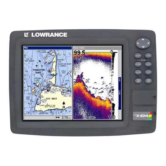
Pub. 988-0151-031 www.lowrance.com LCX-104C Fish-finding Sonar & Mapping GPS Operation Instructions... - Page 2 We reserve the right to do so without notice. All features and specifications subject to change without notice. All screens in this manual are simulated. On the cover: LCX-104C shown. For free owner's manuals and other information, All rights reserved.
-
Page 3: Table Of Contents
Sec. 1: Read Me First! ... 1 Capabilities and Specifications: LCX-104C ... 3 How your Sonar Works... 5 How your GPS Works ... 6 Introduction to GPS and WAAS... 8 How to Use this Manual: Typographical Conventions... 10 Sec. 2: Installation & Accessories ... 13 Preparations... - Page 4 Sonar Operations ... 48 Fish Symbols vs. Full Sonar Chart ... 50 Other Free Training Aids ... 50 Sec. 4: Sonar Options & Other Features ... 53 ASP (Advanced Signal Processing) ... 53 Alarms ... 54 Depth Alarms ... 54 Zone Alarm ...
- Page 5 Upper and Lower Limits ... 84 Zoom & Zoom Bar ... 84 Zoom Pan... 85 Sec. 5: Sonar Troubleshooting... 87 Sec. 6: Basic GPS Operations... 91 Keyboard ... 91 Power/Lights (Turn Unit On and Off) ... 92 Main Menu ... 92 Pages ...
- Page 6 Routes... 125 Create and Save a Route ... 126 Delete a Route ... 128 Edit a Route ... 128 Navigate a Route... 129 Navigate a Route in Reverse ... 130 Trails ... 131 Delete a Trail ... 131 Edit a Trail Name ... 131 Edit a Trail Color ...
- Page 7 Fill Water with White... 146 Map Overlays (Range Rings; Lat/Long Grid) ... 146 Map Datum Selection ... 146 Map Detail Category Selection... 147 Map Orientation ... 148 Overlay Data ... 149 Navionics Charts... 151 To Display a Navionics Chart: ... 151 Port Information ...
- Page 8 A CAREFUL NAVIGATOR NEVER RELIES ON ONLY ONE METHOD TO OBTAIN POSITION INFORMATION. When showing navigation data to a position (waypoint), a GPS unit will show the shortest, most direct path to the waypoint. It provides navigation data to the waypoint regardless of obstructions.
-
Page 9: Sec. 1: Read Me First
The manual is organized into 10 sections. This first section is an intro- duction to the LCX-104C sonar and GPS. It tells you the basics you need to know before you can make the unit look around and tell you where you are, or look below the surface to find some fish. - Page 10 After you've gained some experience with your sonar, you'll want to check out Section 4, which discusses more advanced Sonar Options and Other Features. When you come to a sonar menu command on the unit's screen, you can look it up in the manual by skimming over the table of contents, just flip- ping through Section 3 or scanning through the sonar options in Section 4.
-
Page 11: Capabilities And Specifications: Lcx-104C
5. (Background on GPS begins on page 6.) Capabilities and Specifications: LCX-104C Display:... High-brightness liquid crystal TFT; pro- Resolution:... 640 pixel x 480 pixel resolution; 307,200 total Backlighting:... - Page 12 Sonar sounding depth capability: ... 3,000 feet (915 meters). Actual capability Depth display:... Continuous display. Graph recording:... Up to 512 MB on two MMC (or SD) cards Audible alarms: ... Deep/shallow/fish/zone. Automatic ranging:... Yes, with instant screen updates. Auto bottom track:... Yes Zoom bottom track: ...
-
Page 13: How Your Sonar Works
Position updates: ... Every second. Position points: ... 1,000 waypoints; 1,000 event marker icons. Man Overboard:... MOB feature precisely marks man overboard Audible alarms: ... Arrival/off-course/destination passed/anchor. Graphic symbols for waypoints or event marker icons: ... 42. Routes:... 100; up to 100 waypoints per route. Plot Trails: ... -
Page 14: How Your Gps Works
(fish, structure, bottom) and bounces back to the transducer, which converts the sound back into an electrical signal. The receiver amplifies this return signal, or echo, and sends it to the display, where an image of the object appears on the scrolling sonar chart. - Page 15 The performance doesn't stop there. Stored in the permanent memory of every unit is a basic background map of the entire world. We lock it in here at the factory — you can't change or erase this map. The background map is suitable for many navigation chores, but for maximum accuracy and much more detail, you need our optional map- making software, MapCreate...
-
Page 16: Introduction To Gps And Waas
MMC, custom map files and GPS data files can be used interchangea- bly between your gimbal-mounted LCX-104C and the hand-held iFINDER GPS receiver.) The unit automatically reads Custom Map Files directly from the MMC or SDC. To use a custom map, all you need to do is slide an MMC con- taining a map into the unit. - Page 17 A minimum of three satellites are required to determine a 2D fix. Remember, the unit must have a clear view of the satellites in order to receive their signals. Unlike radio or television signals, GPS works at very high frequencies. These signals can be easily blocked by trees, buildings, an automobile roof, even your body.
-
Page 18: How To Use This Manual: Typographical Conventions
WAAS reception, but terrain, foliage or even large man-made structures frequently block the WAAS signal from ground receivers. You'll find that using your GPS receiver is both easy and amazingly accurate. It’s easily the most accurate method of electronic navigation available to the general public today. - Page 19 Menu Commands A menu command or a menu option will appear in small capital letters, in a bold sans serif type like this: to select this command or option from a menu or take an action of some kind with the menu item. Text that you may need to enter or file names you need to select are show in italic type, such as trail name.
- Page 20 Notes...
-
Page 21: Sec. 2: Installation & Accessories
Installation & Accessories Preparations You can install the sonar and GPS systems in some other order if you prefer, but we recommend this installation sequence: CAUTION: You should read over this entire installation section before drill- ing any holes in your vehicle or vessel! 1. -
Page 22: Recommended Tools And Supplies
Read these instructions carefully before attempting the installation. Determine which of the mounting positions is right for your boat. Use extreme care if mounting the transducer inside the hull, because once it is epoxied into position, the transducer usually cannot be removed. Remember, the transducer installation is the most critical part of a sonar installation. -
Page 23: How Low Should You Go
2. The transducer should be installed with its face pointing straight down, if possible. 3. If the transducer is mounted on the transom, make sure it doesn't inter- fere with the trailer or hauling of the boat. Also, don't mount it closer than approximately one foot from the engine's lower unit. -
Page 24: Shoot-Thru-Hull Vs. Transom Mounting
However, there are times when you may need to adjust the transducer slightly higher or lower. (The slots in the mounting brackets allow you to loosen the screws and slide the transducer up or down.) If you fre- quently lose bottom signal lock while running at high speed, the trans- ducer may be coming out of the water as you cross waves or wakes. - Page 25 bracket with the letter "A" aligned with the dot stamped into the metal bracket. This position sets the transducer's coarse angle adjustment for a 14° transom. Most outboard and stern-drive transoms have a 14° angle. Align plastic ratchets in bracket. B.
- Page 26 Transducer Transducer bracket Ratchet Ratchet Add ratchets to bracket and transducer. 2. Aligning the transducer on the transom. A. One-piece bracket: Slide the transducer between the two ratch- ets. Temporarily slide the bolt though the transducer assembly and hold it against the transom. Looking at the transducer from the side, check to see if it will adjust so that its face is parallel to the ground.
- Page 27 B. Two-piece bracket: Assemble the transducer and bracket as shown in the following figure. Temporarily slide the bolt though the transducer assembly but don't tighten the nut at this time. Hold the assembled transducer and bracket against the transom. Looking at the transducer from the side, check to see if it will adjust so that its face is parallel to the ground.
- Page 28 B. Two-piece bracket: Once you determine the correct position for the ratchets, assemble the transducer as shown in the figure in step 2B. Don't tighten the lock nut at this time. 4. Drilling mounting holes. Hold the transducer and bracket assembly against the transom. The transducer should be roughly parallel to the ground.
- Page 29 Both bracket types: Attach the transducer to the transom. Slide the transducer up or down until it's aligned properly with the bottom of the hull as shown in the preceding and following figures. Tighten the bracket's mounting screws, sealing them with the caulking compound. Adjust the transducer so that it's parallel to the ground and tighten the nut until it touches the outer washer, then add 1/4 turn.
-
Page 30: Trolling Motor Bracket Installation
7. Make a test run to determine the results. If the bottom is lost at high speed, or if noise appears on the display, try sliding the trans- ducer bracket down. This puts the transducer deeper into the water, hopefully below the turbulence causing the noise. Don't allow the transducer bracket to go below the bottom of the hull! TROLLING MOTOR BRACKET INSTALLATION (single-frequency only) -
Page 31: Transducer Orientation And Fish Arches
TRANSDUCER ORIENTATION AND FISH ARCHES If you do not get good fish arches on your display, it could be because the transducer is not parallel with the ground when the boat is at rest in the water or at slow trolling speeds. Transducer aimed too far back Full fish arch... - Page 32 transducer installation can be made on hulls with flotation materials (such as plywood, balsa wood or foam) between layers of fiberglass if the material is removed from the chosen area. Fill with epoxy Flotation material Epoxy to hull first Epoxy the transducer to a solid portion of the hull. For example, some (but not all) manufacturers use a layer of fiberglass, then a core of balsa wood, finishing with an outer layer of fiberglass.
- Page 33 cation that shot through the hull the best and follow the instructions on the following pages for a shoot-thru-hull mounting. Transducer location (high speed) Shoot-thru-hull transducer locations for high speed or trolling speed operation. Shoot-thru-hull Installation 1. Make sure the area is clean, dry and free of oil or grease, then sand both the inside surface of the hull and the face of the transducer with 100 grit sandpaper.
-
Page 34: Speed/Temperature Sensors
Place the transducer into the epoxy, twisting and turning it to force any air bubbles out from under the transducer face. The face of the transducer should be parallel with the hull, with a minimum amount of epoxy between the hull and transducer. After the epoxy dries, route the cable to the sonar unit. -
Page 35: Sensor Chart
MY-4X Cable Three-temperature sensor installation Three-temperature sensor installation with speed Sensor Chart Sonar unit rear view Two-temperature sensor installation Temperature sensor built into transducer TS-2X temperature sensor TS-3X temperature sensor SP-X speed sensor... -
Page 36: Optional Speed Sensor Installation
Optional Speed Sensor Installation This unit can display speed and distance traveled; the feature requires a speed sensor which may or may not come packaged with your unit. (If you wish to purchase an optional additional sensor for your unit, refer to the accessory ordering information inside the back cover of this manual.) The following instructions describe how to install the speed sensor. -
Page 37: Gps Antenna/Receiver Module
Transom Speed sensor mounting configuration: side view (left) and rear view (right.) If the base of the transom has a radius, fill the gap between the tran- som and the sensor with the caulking compound. This will help ensure a smooth water flow. Route the sensor's cable through or over the transom to the sonar unit. -
Page 38: Power Connections
You need to select an antenna installation location that has a clear, un- obstructed view of the sky. After the module is installed, route the cable to the unit, plug it in the center socket on the back and your system is ready to use. -
Page 39: Nmea/Dgps Cable Connections
The most popular DGPS system relies on a grid of ground-based trans- mitters that send correction signals to DGPS receivers. These in turn, connect to the GPS receiver (such as the LCX-104C). Lowrance offers an optional DGPS receiver for your unit. - Page 40 Com-1 wiring to receive DGPS position information Orange (Receive) Com-1 Shield (Ground) To unit Com-1 wiring to receive NMEA position information from some other GPS receiver. Yellow (Transmit) Com-1 Shield (Ground) To unit Com-1 wiring to transmit NMEA position information to another NMEA-compatible device.
-
Page 41: Mounting The Unit: Bracket Or In-Dash
Sonar unit, rear view Power/Data socket Com port data wires (three) Note: External speaker wires in power/data cable not shown. Mounting the Unit: Bracket or In-Dash You can install the unit on the top of a dash with the supplied gimbal bracket. - Page 42 12.2 [310.3] [91.8] [231.3] Inch [Millimeter] [58] Front view (left) and side view (right) showing dimensions of the so- nar/GPS unit when mounted on gimbal bracket. Cable hole Screw mounting hole Front Install the gimbal bracket. Orient the bracket so the arms slope toward the front of your unit.
-
Page 43: Mmc Or Sdc Memory Card Installation
Once a location is determined, use the bracket as a template and mark the mounting holes and the hole for the cables. Drill a 1-inch (25.4 mm) hole in the dash for the power, transducer and antenna cables. Screw the bracket to the mounting surface. To pass all connectors through the 1"... -
Page 44: Other Accessories
Thumb screw Memory card compartment with a 16 MB MMC card installed. To remove an MMC 1. Open the card compartment door by unscrewing the thumb screw. The screw should only be finger tight. If it was over-tightened, use a thumbnail, a coin or a screwdriver to open the door. -
Page 45: Mmc And Mapcreate
its anti-glare properties, always use the special cleaner available from your dealer or LEI Extras. To remove fingerprints, water spots, dust or other grime from the screen, hold the bottle about 6 inches (15 cm) from the screen and spray. Wipe immediately with a clean, dry, lint-free cloth. MMC and MapCreate Other available accessories include MMC cards, MMC card readers and MapCreate™... -
Page 46: Face Cover
You can purchase an external speaker at your nearest audio electronics store. The unit is designed to work with most speakers, but make sure to buy one that meets these minimum requirements: • Minimum 8-ohm resistance • Minimum 5-watt power In your vessel or vehicle, mount the speaker wherever you want to hear your unit's sounds. -
Page 47: Sec. 3: Basic Sonar Operation
BUT, if you just can't wait to get on the water, turn to the one- page Quick Reference on page 47. Keyboard LCX-104C sonar/GPS unit, front view, showing sonar screen, keyboard and access doors for the MMC compartment. 1. PWR/LIGHT (Power & Light) – The PWR key turns the unit on and off and activates the backlight. -
Page 48: Power/Lights (Turn Unit On And Off)
3. MENU – Press this key to show the menus and submenus, which allow you to select a command or adjust a feature. This also accesses search functions for streets, intersections, addresses and highway exits. 4. ARROW KEYS – These keys are used to navigate through the menus, make menu selections, move the map and sonar chart cursors and enter data. - Page 49 Used to stop navigating after you have reached your destina- tion waypoint, Point of Interest or map cursor location; or after you reach the end of a route or trail. Sonar Setup command: sets various sonar options. GPS Setup command: sets various GPS receiver options.
-
Page 50: Satellite Status Page
System Setup command: sets general configuration options. Sun/Moon Calculations command: finds the rising and setting time of the sun and the moon. Trip Calculator command: shows trip status and statistics. Timers command: controls the up timer, down timer and alarm clock settings. -
Page 51: Navigation Page
WARNING: Do not begin navigating with this unit until the numbers have stopped flashing! Satellite Status Page showing satellite lock-on with a 3D position acquired (latitude, longitude and altitude), including WAAS reception. Navigation Page This screen has a compass rose that not only shows your direction of travel, but also the direction to a recalled waypoint. -
Page 52: Sonar Page
always at the top of the screen. The arrow in the center of the screen is your present position. It points in the direction you're traveling. Map Page, showing position on Bull Shoals Lake, Arkansas. At left is the full map option. At right, map with sonar option. Map Page is also the default screen that appears when you turn on the unit. - Page 53 FlashGraf At left, Pages Menu, showing sonar chart display option commands. At right, Sonar Page in full sonar chart display mode. Sonar chart display options (from left) split zoom and split frequency. Sonar chart display options (from left) digital data and FlashGraf . Tip: You can adjust the horizontal window size on pages with two major windows, such as FlashGraf.
- Page 54 Sonar Page Menu. Most of these functions are discussed in Sec. 4. Digital data overlay (depth & temperature) Fish arches Structure Sonar Page, showing full sonar chart mode. You can customize how the Sonar Page displays its pictures and other data in many ways.
-
Page 55: Lcx-104C Sonar Quick Reference
LCX-104C Sonar Quick Reference 1. Mount the transducer, antenna and unit. Connect the unit to electric power and the transducer. (If GPS operation is desired, connect GPS antenna, too.) Make sure the MMC is in. (See complete installation de- tails beginning on page 13.) 2. -
Page 56: Sonar Operations
Sonar Operations As you can see from the quick reference on the previous page, basic operation is pretty easy, right out of the box. If you are a sonar novice, try operating the unit with the factory defaults until you get a feel for how it's working. As you're learning the basics, there is one setting you might want to tinker with from time to time —... - Page 57 Adjusting sensitivity in Auto Sensitivity Mode is similar to manually ad- justing a car's speed with the accelerator pedal while cruise control is on. You can tell the car to run faster, but when you let off the gas the cruise control automatically keeps you from running slower than the minimum speed setting.
-
Page 58: Fish Symbols Vs. Full Sonar Chart
Important Tip: While you are experimenting and learning, it's possible to scramble the settings so that the sonar picture disappears from your screen. If that happens, remember that it's easy to switch back to full automatic operation by simply restoring the factory auto settings. Here's how: To Restore Factory Settings 1. - Page 59 Sonar Tutorial, which includes animated illustrations and more pic- tures of actual sonar returns, all described in detail. There's even a "printer friendly" version of the tutorial available on our web site…it makes a great supplement to this operation manual! You can also download a free copy of our Sonar Viewer software.
- Page 60 Free training emulator is available for your unit on our web site. The emulator works exactly like your real sonar/GPS unit. Using the Sonar Simulator and GPS Simulator features, it allows you to play back sonar logs, run GPS routes and trails, even create real waypoints you can use in the field! You can even take snapshots of the Sonar Chart and print them or e-mail them to friends.
-
Page 61: Sec. 4: Sonar Options & Other Features
Section 4: Sonar Options & Other Features Material in this section is arranged in alphabetical order. ASP (Advanced Signal Processing) The ASP feature is a noise rejection system built into the sonar unit that constantly evaluates the effects of boat speed, water conditions and interference. -
Page 62: Alarms
Alarms This unit has three different types of sonar alarms. The first is the Fish Alarm. It sounds when the Fish I.D. feature determines that an echo is a fish. Another alarm is the Zone Alarm, which consists of a bar on the side of the screen. -
Page 63: Zone Alarm
4. Press ← to HALLOW 5. To turn off the alarm, press ONAR LARMS To switch to a different depth setting, open the Sonar Alarms menu and repeat the instructions in step 3 above. To adjust and turn on the deep alarm: 1. -
Page 64: Fish Alarm
4. To set the lower boundary for the Zone Alarm, use ← or→ to select , then press ↑ or ↓ to move the bottom of the bar to the desired OWER depth. 5. Press |← to EXIT echo — fish, bottom, structure — within the zone alarm's depth range will trigger the zone alarm. -
Page 65: Chart Speed
For example, if you figure the sensor is reading 10 percent faster than actual speed, you will enter – 10 in the calibration window. If the sen- sor is reading 5 percent slower than true speed, you will enter + 5 in the window. -
Page 66: Colorline
If you do experiment with chart speed, remember to reset it to maxi- mum when you resume trolling or moving across the water at higher speed. To change chart speed: 1. From the Sonar Page, press 2. The Chart Speed Control Bar appears. Press ↓ to decrease chart speed;... - Page 67 Fig. 1A Fig. 1B Fish near Hard structure structure Colorline Fig. 2A Fig. 2B Hard Muddy bottom bottom Colorline Fig. 3A Fig. 3B Hard Muddy bottom bottom ColorLine This series of figures shows how different ColorLine settings can reveal more information. The "A" figures to the left show locations with Color- Line set at the factory level of 70 percent.
-
Page 68: Depth Cursor
Depth Cursor The depth cursor consists of a horizontal line with a digital depth box on the right side. The numbers inside the box show the depth of the cursor. At left, Sonar Page menu with Depth Cursor command selected. At right, sonar chart with the depth cursor active. -
Page 69: Depth Range - Manual
At left, Sonar Page menu with Depth Range command selected. At right, the Depth Range Control Scale. 2. The Depth Range Control Scale appears. Press ↑ or ↓ to select a dif- ferent depth range. A black bar highlights the selected range. Range numbers in gray cannot be selected. - Page 70 Changing the upper and lower limits gives you far greater control over the depth range. This feature lets you "zoom in" the display in almost unlimited combinations. Nearly any segment of the water column, from the surface to the bottom can be shown. This enlarges the sonar targets to best suit your fishing needs and water conditions.
-
Page 71: Fastrack
To turn off upper and lower limits: From the Sonar Page, press FasTrack This feature automatically converts all echoes to short horizontal lines on the display's far right side. The graph on the rest of the screen con- tinues to operate normally. FasTrack gives you a rapid update of condi- tions directly under the boat. - Page 72 Does that mean Fish I.D. is broken? No — the feature is simply inter- preting sonar returns in a specific way to help take some of the work out of reading the screen. Remember: Fish I.D. is one of the many tools we provide so you can analyze your sonar returns for maximum fish finding information.
-
Page 73: Fishtrack
To turn the Fish I.D. feature on: 1. From the Sonar Page, press 2. Press → ↓ or → to To turn off Fish I.D., repeat the instructions in step 1. FishTrack The FishTrack feature shows the depth of a fish symbol when it ap- pears on the display. -
Page 74: Hyperscroll
The 200 kHz transducer will give you better detail and definition, but less depth penetration. The 50 kHz transducer will give you greater depth penetration, but a little less detail and less definition. (Remember, all sonar units typically read deeper in fresh water than in salt water.) There is a common exception to these rules of thumb. -
Page 75: Noise Rejection
nar Simulator.) If you have a personal computer and Internet access, visit our web site, www.lowrance.com, and download the free Sonar Viewer and the emulator for your unit. These programs will allow you to replay sonar logs on your personal computer. At left, the Sonar Page menu with the Log Sonar Chart Data command selected. - Page 76 Overlay Data command on the Sonar Menu, at left. Overlay Data Shown selection menu, right. In this example, we scrolled down the data list to highlight "Ground Speed." When selected, the data type shifts to the top of the data list and a check mark appears beside the data type.
-
Page 77: Ping Speed & Hyperscroll
2. Press ↓ or ↑ to select Data Type|press → or ← to Data Size| The selected data type will be displayed in the new size. (To change the font size for another Data Type, press ginning with step two above.) 3. -
Page 78: To Change Ping Speed
However, when you are running at high speeds, or just want the fastest possible screen update, you may want to use the HyperScroll feature. When you change the Ping Speed to any setting greater than 50 per- cent, the unit automatically enters HyperScroll mode. These faster ping rates allow you to maintain a high-detail picture on the screen, and the screen refresh rate and chart scroll speed can keep pace with the boat as it moves quickly over the bottom terrain. -
Page 79: Reset Options
When you boost ping speed and switch into HyperScroll, the width of the FasTrack bar graph display doubles in width at the right side of the screen. The allows you to better see the virtually instantaneous sonar returns, just as you would on a flasher sonar unit. For more informa- tion on FasTrack, see it's entry in this section. -
Page 80: Set Keel Offset
Set Keel Offset This unit measures water depth from the face of the transducer. Since the transducer is installed below the water surface, the distance dis- played by the digital depth, chart depth scale, chart cursor or fish sym- bols is not the exact water depth. If the transducer is 1 foot below the surface, and the screen shows the water depth as 30 feet, then the ac- tual depth is 31 feet. -
Page 81: Sensitivity & Auto Sensitivity
3. Press → to the first number, then press ↑ to change the number to 1. 4. Press → to the second number, them press ↑ to change the num- ber to 5, then press the water depth from surface to bottom. Sensitivity &... -
Page 82: Sonar Color Mode
At left, Sonar Menu with Sensitivity command selected. At right, the Sensitivity Control Bar. To adjust sensitivity in manual mode: 1. First, turn off Auto Sensitivity: from the Sonar Page, press ENSITIVITY 2. Press ↑ to ENSITIVITY Press ↓ or ↑ to pick a different sensitivity setting. When it's set at the desired level, press To turn Auto Sensitivity back on: From the Sonar Page, press... -
Page 83: Sonar Page & Sonar Chart Display Options
3. Press ↓ or ↑ to Mode Name| 4. Press to return to the Sonar Page. EXIT EXIT Sonar Page & Sonar Chart Display Options The Pages Menu offers five chart display options for units with dual- frequency transducers and four options for units with single-frequency transducers. -
Page 84: Split Zoom Sonar Chart
Full Sonar Chart. The Overlay Data (depth and water temperature) are each set to a different text size. Split Zoom Sonar Chart A split chart shows the underwater world from the surface to the bot- tom on the right side of the screen. The left side shows an enlarged ver- sion of the right side. - Page 85 Split Frequency Sonar Chart page, with 50 kHz view at left and 200 kHz view at right. You can adjust the sensitivity in each window. To adjust sensitivity in auto mode: 1. Press MENU 2. The unit asks which you wish to adjust. Press ← or→ to select the one you want | 3.
-
Page 86: Digital Data/Chart
Digital Data/Chart This mode shows the chart on the right side of the screen. The left side has seven large digital boxes or windows containing: Water Depth; Water Speed (from an optional speed sensor); Water Distance (distance traveled or logged, it also requires a speed sensor); Surface Water Temperature; Tem- perature #2 and #3 and the unit's Voltage. -
Page 87: Flashgraf
2. The Water Speed window title bar flashes, indicating the window contents can be changed. Press type| EXIT Options List for customizing Digital Data windows. At left, the list first appears with Water Speed selected. At right, Maximum Speed has been picked to replace Water Speed in the top digital data window. -
Page 88: Map With Sonar Split Screen
Bottom signal Map With Sonar Split Screen There is a page mode that splits the screen in half, with the map on the left and the sonar on the right. This screen option can be found on the Pages Menu under the Map Page category. Map With Sonar split screen option. - Page 89 At left, Main Menu with Sonar Setup command selected. Center, sub-menu with Sonar Simulator command selected. At right, Sonar Simulator menu, with simulator turned on (check box is checked). NOTE: With Simulate Position checked, the simulator will also automati- cally run the GPS simulator (if GPS data was recorded with the so- nar log).
- Page 90 1. Press MENU MENU 2. Press ↓ to HART 3. Press ↓ or ↑ to select chart name| EXIT While you're in the Sonar Simulator menu, don't forget to check Simulate Position if you want to run the sonar and GPS simulators simultaneously.
-
Page 91: Stop Chart
Stop Chart If you are running multiple units on a boat or using this unit in a car, there are times when you may want to turn off the sonar. This com- mand turns off the sonar and stops the chart from scrolling. Sonar re- starts automatically each time you turn on your unit. -
Page 92: Upper And Lower Limits
Sonar Features menu with Surface Clarity selected. 2. Press → to ENT. URFACE LARITY 3. Press ↓ or ↑ to select clarity level| EXIT EXIT EXIT Surface clutter In the illustration at left, Surface Clarity is turned off. The right view shows Surface Clarity set at High. Upper and Lower Limits See the entry in this section for Depth Range - Upper and Lower Limits Zoom &... -
Page 93: Zoom Pan
For example, pressing the key once will enable a 2X zoom which will show all echoes that are between the top and bottom of the 2X zoom bar. Pressing the key again will give a 4X zoom and only the ech- oes between the top and bottom of the 4X bar will show on the screen. - Page 94 Notes...
-
Page 95: Sec. 5: Sonar Troubleshooting
Section 5: Sonar Troubleshooting If your unit is not working, or if you need technical help, please use the following troubleshooting section before contacting the factory customer service department. It may save you the trouble of returning your unit for repair. For contact information, refer to the last page, just inside the back cover of this manual. - Page 96 This causes the sonar to automatically increase its Discrimination or noise rejection feature. This can cause the unit to eliminate weaker signals such as fish or even structure from the display. 3. The water may be deeper than the sonar's ability to find the bottom. If the sonar can't find the bottom signal while it's in the automatic mode, the digital sonar display will flash continuously.
- Page 97 NOISE A major cause of sonar problems is electrical noise. This usually appears on the sonar's display as random patterns of dots or lines. In severe cases, it can completely cover the screen with black dots, or cause the unit to operate erratically, or not at all. To eliminate or minimize the effects of electrical noise, first try to determine the cause.
- Page 98 Notes...
-
Page 99: Sec. 6: Basic Gps Operations
BUT, if you just can't wait to get outside, turn to the one-page Quick Reference on page 103. Keyboard LCX-104C sonar/GPS unit, front view, showing sonar screen, keyboard and access doors for the MMC compartment. 1. PWR/LIGHT (Power & Light) – The PWR key turns the unit on and off and activates the backlight. -
Page 100: Power/Lights (Turn Unit On And Off)
3. MENU – Press this key to show the menus and submenus, which allow you to select a command or adjust a feature. This also accesses search functions for streets, intersections, addresses and highway exits. 4. ARROW KEYS – These keys are used to navigate through the menus, make menu selections, move the map cursor and sonar chart cursor and enter data. - Page 101 Point of Interest or map cursor location; or after you reach the end of a route or trail. Sonar Setup command: sets various sonar options. GPS Setup command: sets various GPS receiver options. System Setup command: sets general configuration options. Sun/Moon Calculations command: finds the rising and setting time...
-
Page 102: Sonar Page
of the sun and the moon. Trip Calculator command: shows trip status and statistics. Timers command: controls the up timer, down timer and alarm clock settings. Browse MMC Files command: this allows you to view the installed MMC card and the files it contains. Pages The unit has four Page displays that represent the four major operating modes. - Page 103 You can use this to see which satellites are obstructed by obstacles in your immediate area if the unit is facing north. The GPS receiver is tracking satellites that are in light blue. The re- ceiver hasn't locked onto a satellite if the number is dark blue, there- fore it isn't being used to solve the position.
-
Page 104: Navigation Page
rently has. The smaller the position error number, the better (and more accurate) the fix is. If the position error flashes dashes, then the unit hasn't locked onto the satellites, and the number shown isn't valid. The Satellite Status Page has its own menu, which is used for setting various options. - Page 105 NOTE: Remember, when the Speed, Track and Position information dis- plays are flashing, satellite lock has not been achieved and no posi- tion fix has been determined. A question mark will also flash on the present position arrow in the center of the compass rose. Speed (ground speed) is the velocity you are making over the ground.
-
Page 106: Map Page
Current track or heading, shown in degrees Compass bearing to destination Navigation Left cross information track error line displays Navigation Page, backtracking a trail while creating a new trail. In the example figure above, the driver is headed north (a 355º track) toward a waypoint 355º... - Page 107 The map zoom range is the distance across the screen. This number shows in the lower right corner of the screen. In the first example fig- ure below, the range is 4,000 miles from the left edge of the map to the right edge of the map.
- Page 108 The medium-detail U.S. maps contain: all incorporated cities; shaded metropolitan areas; county boundaries; shaded public lands (such as national forests and parks); some major city streets; Interstate, U.S. and state highways; Interstate highway exits and exit services informa- tion; large- and medium-sized lakes and streams; and more than 60,000 navigation aids and 10,000 wrecks and obstructions in U.S.
- Page 109 can reduce screen clutter and make streets and other map features easier to see by simply turning off the display of POIs you're not watching for. (To see how, check the text on Map Detail Category Selection, page 147. It shows how to use the Map Categories Drawn menu to turn individual POI displays off and on.) Even though their display is turned off, you can still search for POIs and their icons will pop-up when your unit finds them for you.
- Page 110 The following page contains a 12-step quick reference for the most basic GPS operations. If you don't want to carry the manual with you as you practice with the LCX-104C, you might consider photocopying this quick reference page and tucking it into your pocket.
-
Page 111: Gps Quick Reference
1. Connect the unit to electric power and the antenna module. Make sure the MMC is in. (See complete installation details beginning on page 13.) 2. To turn on the LCX-104C, press and release 3. Opening screen displays map of North America at the 4,000 mile zoom range. -
Page 112: Find Your Current Position
Find Your Current Position Finding your current position is as simple as turning the unit on. Un- der clear sky conditions, the unit automatically searches for satellites and calculates its position in approximately one minute or less. NOTE: "Clear sky" means open sky, unobstructed by terrain, dense foliage or structures. -
Page 113: Selecting Any Map Item With The Cursor
Cursor line Selected airport The selected airport to the northwest is 4.25 miles away. Selecting Any Map Item With the Cursor 1. Use the zoom keys and the arrow keys to move around the map and find the item you wish to select. 2. - Page 114 Press 5. The POI information screen appears. (This is how you can use the LCX-104C as a business phone directory!) If you wanted to navigate there, you could press , since the command is highlighted.
-
Page 115: Set A Waypoint
NOTE: Search works from mapping and POI data loaded in the LCX-104C. If you do not have a high-detailed custom map (containing POI data) for the area you are searching loaded on the MMC, you may not find anything. -
Page 116: Create Waypoint On Map
Step 1. Step 3. Sequence for setting a waypoint. Step 1: while traveling, quickly press WPT twice to call up Find Waypoint screen (seen in Step 2) and set a point. Step 3: a message says the waypoint has been saved. Step 4: ve- hicle continues on its way;... -
Page 117: Create Waypoint By Entering A Position
Create Waypoint by Entering a Position 1. Press |→ to 2. Press ↓ to NTERED 3. Press → to ATITUDE change the first character, then press → to the next character and re- peat until the latitude is correct. Press 4. -
Page 118: Set Man Overboard (Mob) Waypoint
Course line (red) Off course range, set at 0.20 mile Navigation Page, navigating toward waypoint 004 and leaving a trail. Set Man Overboard (MOB) Waypoint One of boating's most terrifying events is having a friend or family member fall overboard. This situation can be deadly on any body of wa- ter —... -
Page 119: Navigate To Cursor Position On Map
Navigating to Man Overboard: Navigation Page, left, and Map Page, right. The victim is astern of the vessel; the GPS shows which direc- tion to steer to for the rescue. The man overboard position is also stored in the waypoint list for future reference. - Page 120 Navigate to cursor. In this example, the cursor has selected the town of Oologah, Oklahoma. 3. Press and the LCX-104C will begin navigating to the cur- MENU sor location. The Map Page will display a red line from your current position to the cur- sor position.
-
Page 121: Navigate To A Point Of Interest
On the screen, trails are represented by a magenta line extending from the back of the current position arrow. The LCX-104C is set at the factory to automatically create and record a trail while the unit is turned on. The unit will continue recording the trail until the length reaches the maximum trail point setting (default is 2,000, but the unit can record trails 9,999 points long). - Page 122 Visible Active symbol symbol Sequence for saving a trail and beginning a new one. At left, My Trails command. Center, the Trails Menu. The arrow to the right of Trail 17 indicates the trail is "active," and the check to the left indicates the trail is visible on the map display.
-
Page 123: Displaying A Saved Trail
Tip: Another quick way to stop recording one trail and begin a new one is to use the New Trail command: Press RAILS Caution: You also have the option of completely turning off trail record- ing, under the trail Options command. However, if the Update Active Trail option is left turned off, it will cancel the automatic trail creation feature. -
Page 124: Visual Trailing
If you are already located at or near the beginning of your trail, the arrival alarm will go off as soon as you hit Enter. Just press clear the alarm and proceed. 5. Now, begin moving and follow your LCX-104C. 6. When you reach your destination, be sure to cancel your navigation: press... - Page 125 Figure 1. Figure 2. Figure 3. Figure 4. Navigate a trail menu sequence: Fig. 1, My Trails command. Fig. 2, Trails Menu. Fig. 3, Edit Trail Menu. Fig. 4, Edit Route Menu with Navigate command highlighted for Trail 6. A trail is always converted to a "route"...
-
Page 126: Navigate A Back Trail (Backtrack, Or Reverse)
6 and must turn west to follow the trail. Arrival alarm goes off and bearing arrow swings around to say turn left (west), toward the next waypoint, trail point 7. The LCX-104C now shows navigation information to point 7, which is 1.99 miles away. -
Page 127: Transfer Custom Maps And Gps Data Files
MMC (as a GPS Data File) in order to store it on your per- sonal computer. GPS Data Files stored on an MMC must be copied from the card to the LCX-104C's internal memory before the unit can read them. Here's how: 1. - Page 128 2. The Transfer My Data menu includes a message which tells you if an MMC is present or not. If no MMC is present, you must first insert a card into the LCX-104C in order to activate the Load or Save commands. To transfer data from the unit to the MMC: press To transfer data from the MMC to the unit: press →...
-
Page 129: Cancel Navigation
Figure 3. Figure 4. These figures show the menu sequence for loading a GPS Data File from an MMC into the LCX-104C's memory. Cancel Navigation You can turn off any of the navigation commands after you reach your destination or at any other time by using the Cancel Navigation com- ←... - Page 130 Notes...
-
Page 131: Sec. 7: Advanced Gps Operations
Advanced GPS Operations Find Distance From Current Position To Another Location 1. While on the Map Page press: 2. Center your cursor over the position you want to find the distance to. A rubber band line appears, connecting your current position to the cursor's location. -
Page 132: Create Icon On Map
These are sometimes referred to as event marker icons. The LCX-104C has 42 different symbols you can pick from when creating an icon. Icons are similar to waypoints, but they do not store as much informa- tion (like names) as waypoints do. -
Page 133: Navigate To An Icon
The Delete All Icons command will ask if you are sure. Press ← to . All icons will be deleted from the map. The Delete by Symbol command will launch the Select Symbol menu. Press ← or ↑ or → or ↓ to select the icon symbol to delete, then press . -
Page 134: Create And Save A Route
MapCreate's manual for creating a route and saving it as part of a GPS Data File (file format *.usr). Copy the GPS Data File to an MMC and insert the MMC in the LCX-104C. (See Sec. 2 for instructions on in- stalling MMCs. To load the GPS Data File into the LCX-104C memory, see the entry on Transfer Custom Maps &... - Page 135 Edit Route menu, left. Edit Route Waypoints menu, right, with Add From Map command selected. 3. Use the Zoom keys and arrow keys to move the map and cursor until the cursor is centered on the spot where you want your route to begin. (If you are starting at your current position or the current cursor posi- tion, you are already at the starting spot.) 4.
-
Page 136: Delete A Route
7. To save your route, press Route screen, with the route automatically named "Route 1" and stored in the LCX-104C's internal memory. (In our example, Route 1 already existed, so the unit automatically made "Route 2.") You can edit the route and run other commands, but if you are finished... -
Page 137: Navigate A Route
3. Use ↓ and ↑ to select a command from the Edit Route Waypoints menu and press route by clicking on a map location with the cursor. Add Waypoint calls up the Waypoint List so you can insert a waypoint from the list. Re- move Waypoint will delete the waypoint from the route. -
Page 138: Navigate A Route In Reverse
Navigate a Route in Reverse Here's how you run a route backward, from the end waypoint to the beginning waypoint: 1. From the AVIGATION press |↓ to MENU MENU 2. Press ↓ to select route name| |← to VERSE AVIGATE 3. -
Page 139: Trails
Trails Delete a Trail This command Press MENU MENU |← to ELETE RAIL Tip: You can also delete all trails at once: 1. Press MENU 2. Press → to Edit a Trail Name To edit a trail name: press . Press ↑ or ↓ to change the first character, then press name| →... -
Page 140: Utilities
then press → to the next character and repeat until the pattern is cor- rect. Press , then page display. At left, Edit Trail Menu with Pattern option selected. At right, edited Utilities Utilities are useful tools for traveling or for outdoor activities. Alarm Clock To get to the alarm clock menu: press LARM... -
Page 141: Edit A Waypoint (Name, Symbol, And Position)
To delete a waypoint from the map: 1. Use the arrow keys to select the waypoint with the cursor. 2. Press |→ to the previous page and clear the cursor, press To delete all waypoints at one time: press |↓ to ETUP ELETE to the previous page, press... -
Page 142: Set A Waypoint By Projecting A Position
accuracy by helping to eliminate errors caused by atmospheric condi- tions and other factors. 1. Press |→ to 2. Press ↓ or ↑ to VERAGE 3. Wait while the unit takes points to average for the position. (The greater the number of points, the greater the accuracy.) When the desired number of points accumulates, press 4. -
Page 143: Sec. 8: System & Gps Setup Options
Section 8: System & GPS Setup Options Alarms This unit has several GPS alarms. The factory default setting has all the alarms turned on. You can turn the alarms off and on and change their distance settings. You can set an arrival alarm to flash a warning message and sound a tone when you cross a preset distance from a waypoint. -
Page 144: Auto Satellite Search
It then searches for only those satellites. When your GPS receiver is turned on for the first time, it doesn't know what your position or elevation (altitude) is. It does know the current UTC time and date since these were programmed into it at the factory and an internal clock keeps the time while the unit is turned off. -
Page 145: Check Mmc Files And Storage Space
GPS Auto Search on the Satellite Status Menu. You can force the unit to immediately kick into auto search mode. Here's how: 1. Press until you are on the Satellite Status screen. PAGES 2. Press |↓ to MENU Check MMC Files and Storage Space To check MMC Files: Press |↓... -
Page 146: Configure Dgps
Menus for changing Com Port settings. For connectors and wiring information for another device, see page 33. For assistance in configuring the unit to communicate with another device, consult the factory; customer service phone numbers are in the back of this manual. Also see the entries below for Configure DGPS and Configure NMEA. -
Page 147: Configure Nmea
Configure NMEA You can configure the unit to use specific NMEA sentences. 1. Press MENU MENU 2. Press ↓ to OMMUNICATIONS 3. A menu appears showing the prefixes of the available NMEA sen- tences. A check mark next to a prefix means the prefix is in use. Use ↑ ↓... -
Page 148: To Setup Loran Td
you must be in the respective country. This unit will pick the matching datum for you when you select the grid. See the entry on Map Datum Selection for more information. The military grid reference system (MGRS) uses two grid lettering schemes, which are referred to as standard and standard + 10 MGRS on this unit. - Page 149 This is generally at the bottom of the paper map. It's shown as a ratio, for example 1:24000. Press returns to the Configure Map Fix screen. Configure a map fix so the LCX-104C can find your position on a printed chart or topographical map. |↓ to...
-
Page 150: Customize Page Displays
Press ↓ to ELECT point list. Select the waypoint that you saved the reference point under and press . The unit displays a waypoint information screen with the command the Configure Map Fix menu. Finally, press Now press ↑ to OORD . - Page 151 tion) or from a stored waypoint, map place or POI location ( command). You can steer your position and change speed on the map by using the arrow keys ( and speed in the dialog boxes provided on the simulator menu screen. To get to the GPS Simulator: 1.
-
Page 152: Hide Gps Features
3. Begin navigating along the trail/route. (If you are close enough to the first waypoint, the arrival alarm will usually go off as soon as naviga- tion begins. Press press ↑ to increase speed to the desired setting. 4. Press to turn off the steering and speed boxes. -
Page 153: Map Auto Zoom
Map Auto Zoom This receiver has an auto zoom feature that eliminates much of the but- ton pushing that other brands of GPS receivers force you to make. It works in conjunction with the navigation features. First, start navigation to a waypoint. (See the waypoint section for more information on navigating to a waypoint.) Then, with the auto zoom mode on, the unit zooms out until the entire course shows, from the present position to the destination waypoint. -
Page 154: Map Boundaries
Pop-up Map Info From the Map Page, press . With the option highlighted, press and uncheck it (turn off.) After the option is set, press turn to the page display. Map Boundaries From the Map Page, press . With the option highlighted, press OUNDARIES and uncheck it (turn off.) After the option is set, press turn to the page display. -
Page 155: Map Datum Selection
Map Datum Selection Maps and charts are based on a survey of the area that's covered by the map or chart. These surveys are called "Datums." Maps that are cre- ated using different datums will show the same latitude/longitude in slightly different locations. -
Page 156: Map Orientation
Map Menu, left, Map Categories Drawn Menu, right. Map Orientation By default, this receiver shows the map with north always at the top of the screen. This is the way most maps and charts are printed on paper. In Track Up mode, map shows "N" and arrow to indicate north. Map orientation at left is shown in north up and at right, track up. -
Page 157: Overlay Data
Map Menu, left; Map Orientation menu with the North Up map orientation option selected, right. Overlay Data To change the digital data shown on top of the Sonar Page or the Map Page: , use → or ← to select a Page Name, then press First, press PAGES EXIT... - Page 158 Data list showing "Ground Speed" selected to display on Sonar Page. 3. To return to the previous page, press To turn off displayed data: 1. From the Map or Sonar page, press 2. Press ↓ or ↑ to select Data Type| pears from the top of the list and reverts to its previous, unchecked po- sition.
-
Page 159: Navionics Charts
Navionics Charts Your LCX-104C can display Navionics They work just like a MapCreate custom map on an MMC. Left, entrance to Chesapeake Bay in a MapCreate 6 custom map, 10 mile zoom. Center, same position on Navionics chart at 11.15 mile zoom and right, 5.56 mile zoom. -
Page 160: Port Information
2. From the Map Page, press . Use ↑ or ↓ to select the Map Name, then press HOICE EXIT EXIT These figures show menu sequence (from left to right) for selecting a Navionics chart for the South Chesapeake Bay area. 3. -
Page 161: Tidal Current Information
3. To scroll through the Service Categories window: press then use ↑ or ↓ to see the types of services available. As you highlight a different category, the list in the lower window changes. To return to the Map Page, press EXIT EXIT 4. - Page 162 Tidal Current Station icon in animated mode Cursor lines Navionics chart showing Tidal Current Station icon selected by cur- sor. In this example, the tidal current is in flood but it's about to enter the slack water stage. The current is flowing to the west at 0.1 mph. The Tidal Current Information screen displays daily tidal current data for this station on this date at the present time.
-
Page 163: Tide Information
You can look up tidal current data for other dates by changing the month, day and year selection boxes. To select another date: 1. Use → and ← to highlight month, day or year, then press 2. Use ↑ and ↓ to select the desired month, day or year, then press To clear the information screen, press Tide Information Navionics... -
Page 164: Pop-Up Help
Tide Information screen. The Tide Information screen displays daily tidal data for this station on this date at the present time. The graph at the top of the screen is an approximate view of the tidal range pattern for the day, from midnight (MN), to noon (NN) to midnight (MN). -
Page 165: Position Pinning
System Setup menu, left, with Pop-up Help command highlighted. At right, this example shows the Pop-up Help message for the Screen command, located on the Map Menu. Position Pinning When you are standing still or moving at extremely slow speed, a GPS receiver can have trouble determining the direction you are traveling. -
Page 166: Require Dgps
Reset Options Menu, right. Require DGPS You can force the LCX-104C to require DGPS for reporting a valid posi- tion. (The default setting, off, uses DGPS automatically when an op- tional DGPS beacon receiver is connected. However, this auto mode doesn't require DGPS reception to yield a position.) Here's how to turn... -
Page 167: Set Language
slider bar is already selected. Press → or ← to move the ONTRAST bar. The left end of the scale is minimum contrast; the right end is maximum contrast. Screen Command, left, and Screen Menu with Contrast bar selected, right. To adjust the display's brightness: Press ↓... -
Page 168: Set Local Time
1. Press MENU MENU 2. Press ↓ to ANGUAGE 3. Use ↓ or ↑ to select a different language and press now appear in the language you selected. Set Local Time Using the correct local time setting is handy when estimating local ar- rival time while navigating. -
Page 169: Software Version Information
These upgrades make the unit perform better or introduce a new fea- ture or function. You can find out what software version is running in your LCX-104C by using the Software Information command. System Setup command left; Software Information command, center. -
Page 170: Track Smoothing
Once in the Sounds menu: To set Key Press Sounds: With the option highlighted, press check it (turn on) and uncheck it (turn off). After the option is set, press to return to the page display. EXIT EXIT To set Alarm Sounds: Press ↓ to lighted, press to check it (turn on) and uncheck it (turn off). -
Page 171: Delete All Trails
Main Menu, left, Trails Menu, center, Trail Options, right. Delete All Trails To remove all of the trails from memory: from the Trails Menu, press → |← to ELETE Update Trail Option This menu lets you change the way the trail updates occur. WARNING: If you uncheck the Update Trail option, automatic trail creation and recording will be turned off. -
Page 172: Delete Trail
Trail Options menu: Update Time Rate setting, left, and Update Dis- tance setting, right. Specific Trail Options Delete Trail To delete a specific trail: From the Trails Menu, press ↓ to Trail Name| . The Edit Trail menu appears as seen in the following fig- ure. -
Page 173: Units Of Measure
On the Edit Trail menu, press ↓ or ↑ to highlight the section you wish to change, then press this menu. You can also change the trail line color and pattern. For instructions, see the entries on Edit a Trail Color and Edit a Trail Pattern beginning on page 131, Sec. - Page 174 Notes...
-
Page 175: Sec. 9: Searching
NOTE: The background map loaded in your unit lets you search for U.S. Interstate Highway exits and exit services, as well as some land features, including cities and lakes. For a full set of searchable land features, including landmarks, streets, addresses and Points of In- terest, you must load your own high-detail custom map produced with our MapCreate 6 software. - Page 176 Find Address Menu. 3. To enter an address number, press ↑ or ↓ to change the first number, then press → to move the cursor to the next number and re- peat until the number is correct, then press 4. To enter a street name, press ↓ to .
- Page 177 NOTE: We recommend that you do not enter a city name unless the list you are given is too large when searching without it. The unit can actu- ally search quicker without a city and you save time by not entering a city name.
-
Page 178: Find Any Item Selected By Map Cursor
Tip: If the address also happens to be an item in the Point of Interest database, you can look up the item's phone number in the Waypoint Information list. With the address location selected by the cursor on the map, press pears, with the Go To Waypoint command highlighted. -
Page 179: Find Interstate Highway Exits
Find Interstate Highway Exits 1. From the Map Page, press |↓ to , which calls MENU IGHWAY XITS up the Find Exit menu. Find Highway Exits command, left, and Find Exit menu, right. 2. First, select a highway name by pressing , which calls up the Find By Name menu. - Page 180 Find Exit menu, with an exit selected in the Exit List. 4. In the Exit Information screen you have two choices. A. Press navigate or "go to" the exit. B. Press →| "Go To Exit" option, left, "Find On Map" option, right. Tip: You can also look up some additional information on the Exit Serv- ices located near this exit.
-
Page 181: Find Map Places Or Points Of Interest (Poi)
Find Map Places or Points of Interest (POI) ↓ ↑ 1. Press , press to select a map place or POI category, then . (To narrow your search, press → then press ↓ or ↑ to select a press subcategory before pressing .) You will be given two options;... -
Page 182: Find Streets Or Intersections
Find by Name option, left, Find by Name menu, right. 4. When the POI's Waypoint Information screen is displayed, you can choose to "Go To" the POI waypoint by pressing or find it on the map by pressing→| Go To Waypoint POI option, left; Find on Map POI option, right. Find Streets or Intersections Find a Street 1. - Page 183 2. You must first fill in a street name in the First Street dialog box. Press to display the Find By Name menu. There are two options: A. You can spell out the street in the top selection box. Press ↑ or ↓ to change the first letter, then press →...
- Page 184 Map Page showing results of a street search. The cursor points to the located street. If you want to navigate to the found street at the cursor location, just press MENU EXIT Find an Intersection You must enter one street in the First Street dialog box and enter the next street in the Second Street dialog box.
- Page 185 5. The Find Streets menu reappears with the first and second street dialog boxes filled in. In this example, we selected 71st Street as our second street. You could now use similar techniques to select a city or Zip code, but your search will probably be faster if you leave those boxes blank.
-
Page 186: Find Waypoints
Find Waypoints 1. Press 2. If searching for the waypoint By Name, press the Nearest waypoint, press ↓ to jump to step 5 below.) Find Waypoint menu, left; Find By Nearest command, center, 3. If you're looking for nearest, the unit says it is calculating, then a list of waypoints appears. - Page 187 Waypoint Information screens with the Go To Waypoint command se- lected, left, and the Find on Map command selected, right. To clear these menus and return to the previous page, press peatedly. 5. If you're looking by name, there are two options: A. You can spell out the name in the top selection box.
- Page 188 Notes...
-
Page 189: Sec. 10: Supplemental Material
Section 10: Supplemental Material Datums Used by This Unit WGS 1984 Default Adindan Mean for Ethiopia, Sudan Adindan Burkina Faso Adindan Cameroon Adindan Ethiopia Adindan Mali Adindan Senegal Adindan Sudan Afgooye Somalia Ain el Abd 1970 Bahrain Ain el Abd 1970 Saudi Arabia Anna 1 Astro 1965 Cocos Islands... - Page 190 DOS 1968 New Georgia Islands (Gizo Island) Easter Island 1967 Easter Island European 1950 Mean for Austria, Belgium, Denmark, Finland, France, West Germany, Gibraltar, Greece, Italy, Luxembourg, Netherlands, Norway, Portugal, Spain, Sweden, Switzerland European 1950 Mean for Austria, Denmark, France, West Germany, Netherlands, Switzerland European 1950...
- Page 191 North American 1927 Mean for CONUS (Continental United States) North American 1927 Mean for CONUS (East of Mississippi River) including Louisiana, Missouri, Minnesota North American 1927 Mean for CONUS (West of Mississippi River) North American 1927 Alaska North American 1927 Bahamas (Except San Salvador Island) North American 1927...
- Page 192 Bolivia, Brazil, Chile, Colombia, Ecuador, Guyana, Paraguay, Peru, Trinidad & Tobago, and Venezuela South American 1969 Argentina South American 1969 Bolivia South American 1969 Brazil South American 1969 Chile South American 1969 Colombia South American 1969 Ecuador South American 1969 Ecuador (Baltra, Galapagos) South American 1969...
-
Page 193: Fcc Compliance
This device complies with Part 15 of the U.S. Federal Communications Commission (FCC) Rules. Operation is subject to the following two conditions: (1) this device may not cause harmful interference, and (2) this device must accept any interference received, including interference that may cause undesired operation. - Page 194 Notes...
- Page 195 LOWRANCE DATABASES LICENSE AGREEMENT THIS IS A LEGAL AGREEMENT BETWEEN THE END-USER WHO FIRST PURCHASES THIS PRODUCT AS A CONSUMER ITEM FOR PERSONAL, FAMILY, OR HOUSEHOLD USE ("YOU") AND LOWRANCE ELECTRONICS, INC., THE MANUFACTURER OF THIS PRODUCT ("WE", "OUR", OR "US"). USING THE PRODUCT ACCOMPANIED BY THIS LICENSE AGREEMENT CONSTITUTES ACCEPTANCE OF THESE TERMS AND CONDITIONS.
- Page 196 DATABASES LIMITED WARRANTY "We", "our", or "us" refers to Lowrance Electronics, Inc., the manufacturer of this product. "You" or "your" refers to the first person who purchases the product as a consumer item for personal, family, or household use. The Databases Limited Warranty applies to the one or more databases that your product may contain.
- Page 197 LOWRANCE ELECTRONICS FULL ONE-YEAR WARRANTY "We," "our," or "us" refers to LOWRANCE ELECTRONICS, INC., the manufacturer of this product. "You" or "your" refers to the first person who purchases this product as a consumer item for personal, family or household use. We warrant this product against defects or malfunctions in materials and workmanship, and against failure to conform to this product's written specifications, all for one (1) year from the date of original purchase by you.
-
Page 198: How To Obtain Service
How to Obtain Service… …in the USA: We back your investment in quality products with quick, expert service and genuine Lowrance parts. If you're in the United States and you have technical, return or repair questions, please contact the Factory Customer Service Department. -
Page 199: Accessory Ordering Information
Accessory Ordering Information for all countries To order Lowrance accessories such as cables, transducers or MMC cards, please contact: 1) Your local marine dealer or consumer electronics store. Most quality dealers that handle marine electronic equipment or other consumer electronics should be able to assist you with these items. To locate a Lowrance dealer near you, visit our web site, www.lowrance.com and look for the Dealer Locator. -
Page 200: Visit Our Web Site
Visit our web site: Lowrance Pub. 988-0151-031 © Copyright 2002 All Rights Reserved Printed in USA 122002 Lowrance Electronics, Inc.