Table of Contents
Advertisement
Quick Links
Advertisement
Table of Contents

Related Manuals for Samsung SVR-1650


Summary of Contents for Samsung SVR-1650
- Page 1 Premium Security Digital Video Recorder SVR-1650/1640 User’s Manual Thank you for purchasing a Samsung Digital Video Recorder. Before attempting to connect or operate this product, please read these instructions carefully and save this manual for future use. ENGLISH...
-
Page 3: Introduction
Thank you for purchasing the SVR-1650/1640. This is a user manual for SVR-1650/1640. Before product installation and operation, please become thoroughly familiar with this user manual and other manuals referenced by this manual. This user manual and the software and hardware described here are protected by the copyright law. -
Page 4: Table Of Contents
Table of Contents Introduction ...............1 Product warranty and limits of responsibility ........... 1 Chapter 1. Safety Cautions ..........5 Symbols displayed for each item ............5 Chapter 2. Summary .............8 2.1 Features ................8 2.2 Components ................ 11 2.3 Name and Function of Each Part..........11 2.3.1 Front panel ................ - Page 5 SVR-1650/1640 User Manual 4.5.1 Time search ................35 4.5.2 Event search ................. 35 4.5.3 Log search................37 4.6 Recording file playback .............37 4.6.1 Jog dial / shuttle ring............... 38 4.7 Live / Playback screen conversion ..........38 4.8 Digital zoom ................39 4.9 Copy .................39...
- Page 6 5.8.4 TEXT .................69 5.9 Communication setup .............. 70 5.9.1 NETWORK ................70 5.9.2 RS-232.................71 5.9.3 RS-422/485 ................71 5.9.4 E-MAIL ................72 5.10 System setup............... 73 5.10.1 System ................73 5.10.2 HDD.................75 5.10.3 Password ................76 5.10.4 Date setup................77 5.10.5 PTZ ..................
-
Page 7: Chapter 1. Safety Cautions
Symbols displayed for each item Warning Refers to information users need to know in order to prevent serious injury or death. Caution Provides information users need to know in order to prevent minor injury or product damage. Before installation Verify the supplied voltage (AC100V~AC240V) before connecting the power supply. Make sure the power supply is off before installation. - Page 8 Do not apply excessive force when pulling on the power cord. Damaging the cord may cause an electric shock or fire. Random replacement of built-in battery by other types of batteries may cause explosion. The battery shall be replaced by the same battery. The used batteries shall be disposed carefully because they can cause environment pollutions.
- Page 9 SVR-1650/1640 User Manual INFORMATION This equipment has been tested and found to comply with limits for a Class A digital device, pursuant to part 15 of the FCC Rules. These limits are designed to provide reasonable protection against harmful interference when the equipment is operated in a commercial environment. This equipment generates, uses, and can radiate radio frequency energy and, if not installed and used in accordance with the instruction manual, may cause harmful interference to radio communications.
-
Page 10: Chapter 2. Summary
Product functions can be setup conveniently using the mouse and buttons on the front panel. Samsung SVR-1650/1640 is a digital image recorder that can be used as security equipment in banks, apartments, and government and public offices. It is a stand-alone product with proven performance and stability. - Page 11 SVR-1650/1640 User Manual Video recording High image quality MPEG4 video recording is possible. Up to 480 frames(SVR-1650)/120 frames(SVR-1640) per second of recorded video can be stored and pre-event recording can be done for up to 5 seconds before an event occurs. In addition, privacy is protected by the COVERT (image hiding) function.
-
Page 12: Storage Device
Storage device A built-in hard disk drive is provided. User may also select to use DVD+RW and USB memory for backup. Standard storage: Built-in hard disk drive Various backup devices available: DVD+RW and USB memory Network Various networks including LAN, xDSL is supported. Key functions of the product may be manipu lated easily and maintained remotely using the dedicated viewer for PC. -
Page 13: Components
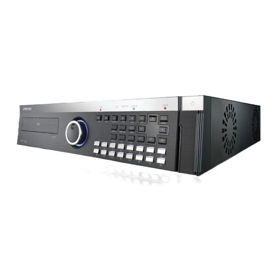
SVR-1650/1640 User Manual 2.2 Components DVR package contains the main body and the following accessories. Please verify whether all accessories are included at the time of purchase. If any accessory is missing, inquire at the point of purchase. 2.3 Name and Function of Each Part 2.3.1 Front panel... -
Page 14: Display Section
Backup(Copy) section Category Function 1. DVD-Multi : DVR for Used to backup recorded/stored images on DVD+RW/CD-RW backup media. Jog/shuttle section Category Function Menu setup values can be adjusted and STEP function can be controlled with JOG. SHUTTLE can be used for moving items 2. - Page 15 SVR-1650/1640 User Manual Function button section Category Function Used for movement in the lower direction 11. ▼ Used for movement in the upper direction. 12. ▲ MENU Used for movement to the left 13. ◀ Used for movement to the right 14.
-
Page 16: Back Connector Terminals
2.3.2 Back connector terminals SENSOR IN 1 2 3 4 1 2 3 4 CONSOLE RELAY OUT I/O terminal names Function CH1~16 BNC input connector terminal for the camera. LOOP OUT BNC output (loop) connector terminal for the camera. RS-232C RS-232C terminal. -
Page 17: Remote Controller
SVR-1650/1640 User Manual 2.3.3 Remote Controller Button names Function 1. MENU Menu screen conversion 2. STATUS System setup information display 3. AUTO Automatic screen conversion 4. D.ZOOM Digital zoom execution 5. SPOT SPOT monitor screen conversion 6. AUX Auxiliary 7. PTZ... -
Page 18: Product Specification
2.4 Product specification Video Items Specification Input method Composite input 16 channels Video input level 1.0 Vp–p, composite NTSC : 480 frames/sec Live screen presentation speed PAL : 400 frames/sec NTSC : 720(horizontal) × 480(vertical) pixels, if entire screen selected Live screen resolution PAL : 720(horizontal) ×... - Page 19 SVR-1650/1640 User Manual Connector terminals Items Specification Video input BNC(16) Loop output BNC(16) Monitor output BNC(2), RCA(Front 1) SPOT Monitor output BNC(1) VGA output 15 pin VGA (PC monitor) Audio RCA input (4), RCA output (2 - including the front)
-
Page 20: Operation Environment
5°C ∼ 40°C Storage temperature –10°C ∼ 60°C Humidity 30% ∼ 90% Video recording Specification Items SVR-1650 SVR-1640 Compression method MPEG-4 Video recording method 2 video recording modes: schedule & event, manual & event NTSC(704×480) : 120 frames/sec 30 frames/sec NTSC(704×240) : 240 fields/sec... -
Page 21: Search And Playback
SVR-1650/1640 User Manual Copy Item Specification DVD+RW (Built-in DVR) Digital copy External USB memory Only DVD+RW, CD-RW media may be used. Search and playback Item Specification Search by time : year, month, day, hour, minute, second Search mode Search by channel : For each channel... -
Page 22: Chapter 3. Installation Method
3.1 Overall connection 3.1.1 Front connection method Connection organization diagram for DVR front side terminals are as follows. *Use only DVD+RW/CD-RW Media Speaker Mouse TV Monitor Memory stick 3.1.2 Back connection method The organization chart for DVR and monitors, CCTV cameras and external devices is as follows. Camera 1~16 Main Monitor SPOT Monitor... -
Page 23: Detailed Connection
SVR-1650/1640 User Manual 3.2 Detailed connection 3.2.1 Rack mount To mount the product, the enclosed rack must be mounted first. Mount sequence is as follows. The enclosed rack mount is mounted on the product. The product is mounted on the 19 inch rack. -
Page 24: Video/Audio Connection
3.2.2 Video/Audio connection Main Monitor 1. Camera 2. Monitor Spot Monitor SENSOR IN 1 2 3 4 1 2 3 4 CONSOLE RELAY OUT Audio(Line input) VGA Monitor 3. Voice Speaker 1. Camera Up to 16 CCTV cameras can be connected to DVR. Connect the BNC terminal for each camera to the CAMERA IN terminal in the back of this product. - Page 25 SVR-1650/1640 User Manual 2. Monitor To output screen information to the main monitor, connect the VGA terminal for monitor output in the back of the product and the monitor BNC terminal with a BNC cable. There are 5 monitor output terminals [BNC 3(SPOT 1), RCA 1, VGA 1) and up to 5 auxiliary monitors can be connected.
-
Page 26: External Connector
3.2.3 External connector SENSOR IN SENSOR IN 1 2 3 4 1 2 3 4 1 2 3 4 1 2 3 4 CONSOLE CONSOLE RELAY OUT RELAY OUT 2. Relay Out 6. LAN(Ethernet) 3. RS-422/485 1. Sensor In 4. RS-232C 5. - Page 27 SVR-1650/1640 User Manual 2. Relay output (RELAY OUT) This is an alarm output terminal used to output alarms for sensor, motion detection, video loss and power OFF to external devices. Description Description Normal Open D_IO 0 Digital I/O Common D_IO 1...
- Page 28 3. External control equipment (RS-422/485) This is a terminal for connecting external control equipment. The switch labeled TERM is used to turn ON/OFF terminating resistance for RS–422/485 communication equipment. PORT RS-422 RS-485 RX+ (+Data Receive) Data+ RX- (-Data Receive) Data- N/C (Not connected) N/C (Not connected) PORT A...
- Page 29 SVR-1650/1640 User Manual PORT A : SCC-3100 terminal Controller Terminal DVR PORT A ( PORT 1) RS-485 RS-422 1 or 8 2 or 7 ※ RS-422/485 connection can be selected from the SW1 switch. To connect RS-485: SW1 switch 1, 2 are turned ON.
- Page 30 PORT B : SPD-2200 terminal Speed dome DVR PORT B terminal 9 or 16 10 or 15 ※ If GND is connected, a much sharper image quality can be seen. TERM2 switch 1, 2 must be set to ON.
- Page 31 SVR-1650/1640 User Manual SPD-2500 terminal Speed dome DVR PORT B terminal 9 or 16 10 or 15 ※ If GND is connected, a much sharper image quality can be seen. TERM2 switch 1, 2 must be set to ON. SPD-2300/3000/3300 terminal...
- Page 32 4. Communication port (RS-232C) This is a port used to connect to the PC to control the product. Description Description N/C(Not connected) N/C(Not connected) RxD(Data receive) N/C(Not connected) TxD(Data send) N/C(Not connected) N/C(Not connected) N/C(Not connected) GND(Ground) External devices ATM/POS may be connected and used. 5.
-
Page 33: Chapter 4. Operation Method
4.1 Preoperation inspection items Make sure you verify the input power source voltage before turning on the power. If product used for NTSC is used with a PAL device, it may malfunction initially(recognize as a NTSC device). In this case, if power is turned OFF and ON again, it will recognize the PAL device properly. -
Page 34: Function Screen Display
4.3.1 FUNCTION screen display If Channel 1~16 is setup as screen mode and FUNCTION button is pressed, icons for FUNCTION-LIVE will be activated. FUNCTION icon can be used to setup SPOT, PTZ and PIP. In the FUNCTION-PLAY screen, the following play screen will be displayed. 4.3.2 Single channel screen display If Channel 1~16 button is pressed, each channel is displayed using the entire screen. -
Page 35: Multi Screen Display
SVR-1650/1640 User Manual 4.3.3 Multi screen display If MULTI button is pressed, 16 channels are displayed as a 16 DIVISION screen. If MULTI button is pressed once again, a 4 DIVISION screen is displayed. Each time MULTI button is pressed, a divided screen is displayed following the order for divided screen types setup in [Screen Setup]-[SEQUENCING]. -
Page 36: Recording
4.4 Recording 4.4.1 General recording If REC button is pressed, red LED is turned ON, N is displayed in the upper right corner and video recording is started. If REC is pressed again, video recording is stopped. [RECORD-OFF] is set to ON in password function, password input is needed to stop REC. -
Page 37: Search
SVR-1650/1640 User Manual 4.5 Search If SEARCH button is pressed, the following search menu is displayed. Video recorded items can be searched by time, by event and by date using the menu and played. Log file search is also possible. - Page 38 Channel [CH1∼ 16/ALL] : Select a channel for event search. Event type : Event type can be filtered for all events or [SENSOR/V-LOSS/MD/TEXT]. SENSOR : Sensor events V-LOSS : Video loss events MD : Motion detection events TEXT : Text input events If number of video recording items exceeds the number that can be displayed on one screen, use the (+)/(-) buttons on the remote controller or the main body to move between pages.
-
Page 39: Log Search
SVR-1650/1640 User Manual 4.5.3 Log search Log history can be searched to verify the time for video recording start and stop, power ON/OFF, system time change (CLOCK), menu setup change (SETUP). [LOG] only provides a list and does not play recordings. -
Page 40: Jog Dial / Shuttle Ring
4.6.1 Jog dial / shuttle ring Jog/Shuttle Shuttle ring: Used to increase/decrease play speed and to change play direction, to move between menus Jog dial: Used to search still images in paused state. 4.7 Live / Playback screen conversion If there is a video recording, press the PLAY/PAUSE button from the LIVE screen to get to the PLAY screen. -
Page 41: Digital Zoom
SVR-1650/1640 User Manual 4.8 Digital zoom If FUNCTION button is pressed and digital zoom icon is clicked, zoom function can be used. To move in the expanded screen, use the up/down/left/right buttons. D-ZOOM button operates in the single screen mode for channel 1~16. -
Page 42: Ptz
QUICK COPY (High speed COPY) -If a recording is in progress, it is paused while COPY is carried out. -SVR-1650 : During COPY, none of the functions, except network live, are supported. SVR-1640 : During COPY, All functions are stopped. -
Page 43: Ptz Adjustment
SVR-1650/1640 User Manual 4.10.1 PTZ adjustment After pressing the PTZ button from the single screen, put the cursor on the button and adjust using the shuttle. To adjust camera TILT, after pressing the PTZ button from the single screen, put the cursor on the button and adjust using the shuttle. -
Page 44: Preset Utilization
4.10.3 Preset utilization Select a desired channel from channel 1~16 and select the entire screen mode. Press PTZ to select the PTZ mode (PTZ is displayed in the upper right corner of the screen.) Use the mouse on PRESET, located below PTZ on the screen, to setup the value (1~255). If the desired button between Channel 1 ~ Channel 16 is pressed, the cursor is moved to the button and the ENTER key located on the front of DVR is pressed, the camera operates with preset values setup in advance. -
Page 45: Quick Setup
SVR-1650/1640 User Manual 4.11 Quick setup Collection of frequently used menu items that can be used to modify setup values quickly. It can move to the [Quick Setup] screen by pressing the MENU button on the front of the product. -
Page 46: Pip
4.12 PIP If FUNCTION button is pressed in entire screen mode, the FUNCTION screen is displayed. If the PIP icon is pressed from here, another screen can be viewed together. Live PIP from Live screen 1. Press the FUNCTION button and select the PIP icon. 2. -
Page 47: System Information
SVR-1650/1640 User Manual 4.13 System information If FUNCTION button is pressed, the FUNCTION screen is displayed. If the STATUS icon is clicked from here, system related information is displayed as shown below. As shown on the screen above, video recording program information and version, IP address, MAC address, voice information can be verified. -
Page 48: Chapter 5. Setup Method
5.1 Menu organization Menu organization for DVR is as follows. System Setup Copy Screen Setup Event Setup Quick Setup Record Setup Communication Search Exit... - Page 49 SVR-1650/1640 User Manual Menu organization is as follows. Refer to‘5.5 ~ 5.10’ for details. Exit Screen Setup SAVE SCREEN DO NOT SAVE SEQUENCING DISPLAY COVERT Copy SPOT COPY STATUS Record Setup Search RECORD PROGRAM TIME EVENT Event Setup EVENT System Setup...
-
Page 50: Initial Value Setup
PROGRAM PROGRAM K PRE EVENT DURATION 3 sec RECORD POST EVENT DURATION 10 sec REPEAT RECORD MODE WARNING LEVEL AUDIO IMAGE SIZE 704 x 240(NTSC) PROGRAM PROGRAM K SVR-1650 : M=5, Q=H, E=10, Q=S SVR-1640 : M=1, Q=H, E=3, Q=S... - Page 51 SVR-1650/1640 User Manual Record program(SVR-1650) NTSC Order SIZE MANUAL QUALITY EVENT QUALITY SIZE MANUAL QUALITY EVENT QUALITY 704 X 480 704 X 576 704 X 480 704 X 576 704 X 480 704 X 576 704 X 480 704 X 576...
- Page 52 Record program(SVR-1640) NTSC Order SIZE MANUAL QUALITY EVENT QUALITY SIZE MANUAL QUALITY EVENT QUALITY 704 X 480 704 X 576 704 X 480 704 X 576 704 X 480 704 X 576 704 X 240 704 X 288 704 X 240 704 X 288 704 X 240 704 X 288...
- Page 53 SVR-1650/1640 User Manual Event setup Main menu Lower menu Initial value CHECK MESSAGE BUZZER SWITCH TO EVENT SCREEN EVENT EVENT DISPLAY MIN TIME 3 sec EVENT DISPLAY MAX TIME 5 sec TEXT MONITORING SENSOR TYPE MD CHANNEL CH1~16, ALL ALL AREA SET...
- Page 54 System setup Main menu Lower menu Initial value LANGUAGE ENGLISH KEY BUZZER DEFAULT FIRMWARE DOWNLOAD USER1 - SYSTEM REMOTE LIVE MODE(SVR-1650) SINGLE REMOTE SETUP ENABLE DVR ALIAS REMOTE ID HDD FORMAT HDD1 USER PASSWORD 22222222 ADMIN PASSWORD 11111111 SETUP POWER-ON...
- Page 55 SVR-1650/1640 User Manual Copy Main menu Lower menu Initial value COPY 1.NONE(GSA-H10A) 2.NONE COPY 3.NONE 4.NONE STATUS NO DATA Exit Main menu Lower menu Initial value SAVE DO NOT SAVE...
-
Page 56: Operation Description
5.3 Operation description DVR can be setup easily using the USB mouse. Operation using the mouse Mouse Wheel Left Button Right Button Left button : Used to selelet menu, verify setup values and cancel the popup menu.of main menu. Right button : Used to Function or cancel popup menu. Mouse wheel : Used to change setup values and display popup menu. -
Page 57: Function Menu
SVR-1650/1640 User Manual 5.4 FUNCTION menu 5.4.1 LIVE/PLAY mode For SINGLE mode setup in the LIVE screen, all LIVE functions are activated and displayed. For MULTI mode setup in the LIVE screen, D-ZOOM, PIP, PTZ are inactivated and cannot be setup. - Page 58 STATUS If STATUS button is clicked, information related to the system is displayed. SYSTEM INFORMATION 1 : Displays video recording program status information. SYSTEM INFORMATION 2 : Displays VERSION, IP ADDRESS, MAC ADDRESS and AUDIO information. SPOT If SPOT button is clicked, the SPOT setup screen is displayed. SPOT monitor can be used to view SINGLE or divided screen.
- Page 59 SVR-1650/1640 User Manual AUTO If AUTO button is pressed, each channel and 4 DIVISION screen, 9 DIVISION screen and 16 DIVISION screen are automatically converted and displayed in time interval which was setup in [Screen Setup]–[SEQUENCING] in the conversion menu.
-
Page 60: Menu Screen Description
5.5 Menu screen description Organization of the menu screen is as follows. Main menu Sub menu Setup items Usage method Description of all menu screen setup value selection and modification is based on the assumption that the mouse is used. Main menu : Main menu corresponding to each tab can be selected. -
Page 61: Screen Setup
SVR-1650/1640 User Manual 5.6 Screen setup If [Screen Setup] tab is clicked, lower menu related to [Screen Setup] is displayed as shown below. In screen setup, [SCREEN], [SEQUENCING], [DISPLAY], [COVERT], [SPOT] related setup values may be modified. 5.6.1 Screen Select a channel among the 16 available and setup the channel name, brightness and contrast for that channel. -
Page 62: Sequencing
5.6.2 Sequencing Automatic screen conversion function for the live screen can be setup. Channels are displayed after every set time interval, after automatic conversion, in the following order: [MULTI MODE] SEQ. CH NUMBER : Setup the screen display duration for each channel. Setup range is Channel 1~16, ALL. - Page 63 SVR-1650/1640 User Manual 9 DIVISION interval : Setup display for a 9 DIVISION screen for 9 channels. VIDEO LOSS SKIP [ON/OFF] : If setup as[ON], channels without image signals will be skipped automatically and only channels with image signals will be...
-
Page 64: Display
5.6.3 Display Information to be displayed on the live screen can be selected. DATE & TIME [ON/OFF] : If setup as [ON], current time is displayed in the live screen. HDD FREE SPACE [ON/OFF] : If setup as [ON], remaining capacity for the mounted hard disk drive is displayed. -
Page 65: Covert
SVR-1650/1640 User Manual 5.6.4 Covert One channel among the 16 available may be selected to setup the image hiding function. LIVE COVERT : If image hiding is turned ON, image is not shown for live screen as in V-LOSS and privacy can be protected. -
Page 66: Record Setup
5.7 Record setup If the mouse is moved over the [Record Setup] tab, a video recording related lower menu is displayed as shown below. If ‘ENTER’ key, located in the front of DVR, is pressed or if lower level menu is selected with the mouse, detailed items may be viewed. -
Page 67: Record Program
SVR-1650/1640 User Manual REPEAT RECORD MODE : If HDD capacity is used up during video recording, recording will by continued by overwriting the data at the front of the HDD. ON: If there is no more space left in the HDD, repetitive video recording will be carried out by over writing the oldest data. -
Page 68: Recording Time Table
HIGH 8.8KB 5.3KB 3.5KB 1.8KB 352×240 SUPER HIGH 320×288 SUPER HIGH 5.0KB 2.6KB 1.8KB 0.9KB 1011 This ‘Recording time table’ is about SVR-1650. Maximum video recording frame rate of SVR-1640 is 704x480 : 30fps, 704x240 : 60fps, 352x240 : 120fps... -
Page 69: Event Setup
SVR-1650/1640 User Manual 5.8 Event setup For event video recording, a lower menu like the one shown below can be setup. If ‘ENTER’ key, located in the front of DVR, is pressed or if lower level menu is selected with the mouse, detailed items may be viewed. -
Page 70: Motion Detection
5.8.2 Motion detection Analyze the image input by the camera to detect motion. If any change is detected, it is counted as an event. MD CHANNER : Setup the channel for which motion detection will be carried out. MD SETUP : Setup whether to detect motion for channel that will be used for motion detection. -
Page 71: Relay
SVR-1650/1640 User Manual 5.8.3 Relay If an event occurs, alarm for sensor, motion detection, loss video and power supply can be generated through the output device connected to the RELAY OUT terminal in the back of the product. Blinking green box indicates the state before selection. After selection, it turns yellow. -
Page 72: Communication Setup
5.9 Communication setup Setup items needed to connect a computer to a network. Communication setup screen is as shown below. If ‘ENTER’ key, located in the front of DVR, is pressed or if lower level menu is selected with the mouse, detailed items may be viewed. -
Page 73: Rs-232
SVR-1650/1640 User Manual SWR : If the product is connected to a cable modem or a xDSL modem, IP address will change each time connection to ISP (User’s communicaton company server) is attempted. In this case, the user will not know the changed IP address. If a product using a floating IP is registered on the SWR server, the changed IP can be found when attempting connection with the product. -
Page 74: E-Mail
PORT TYPE: Setup type of port to use. -PORT A: Connect the SCC-3100 controller. -PORT B: Connect the speed dome. -Control method -Controller : Connect PORT A and controller with RS422/485.. Setup the SYSTEM ID corresponding to the connected SCC-3100. (Refer to page 27) -Speed dome : Connect PORT B and speed dome with RS422/485. -
Page 75: System Setup
SVR-1650/1640 User Manual 5.10 System setup System setup screen is as shown below. If ‘ENTER’ key, located in the front of DVR, is pressed or if lower level menu is selected with the mouse, detailed items may be viewed. 5.10.1 System LANGUAGE : Select a language for the menu screen. - Page 76 If [Yes] is selected from the following screen, it will be upgraded. REMOTE LIVE MODE : Used to determine the resolution of each channel on network board.(This mode is supported in only SVR-1650.) REMOTE SETUP[ON/OFF] : Used to determine remote setup mode.
-
Page 77: Hdd
SVR-1650/1640 User Manual 5.10.2 HDD HDD setups information for the mounted hard disk drive. Basic information related to HDD is displayed on the screen. Information for up to 4 hard disk drives can be viewed. HDD FORMAT : Select whether to format the built-in, fixed HDD. If ‘YES' is clicked in the confirmation dialog window, formatting is carried out. -
Page 78: Password
5.10.3 Password Setup password for user and manager to give authorization needed to use the product and to modify the setup. If ‘ENTER’ key, located in the front of DVR, is pressed or if lower level menu is selected with the mouse, detailed items may be viewed. -
Page 79: Date Setup
SVR-1650/1640 User Manual 5.10.4 Date setup It is used to setup date and time for the product. When setup is completed and stored, it is displayed on the live screen. TIME SETUP : Setup the time. From the dialog box shown above, use the mouse wheel or the buttons on the front of the product to modify the setup value. -
Page 80: Ptz
Please setup accurately for the corresponding model. Models that can be used. – Samsung : SPD(SPD-2200, 2300, 2500, 3000, 3300), SRX-100B – Pelco(D) : Speed dome using Pelco ‘D’ protocol - Panasonic : WV-CS854 – SCC : SCC-641/643... -
Page 81: Video Recording Search
SVR-1650/1640 User Manual 5.11 Video recording search For video recording search, time, event and log file retrieval functions are provided. If ‘ENTER’ key, located in the front of DVR, is pressed or if lower level menu is selected with the mouse, detailed items may be viewed. -
Page 82: Event Search
5.11.2 Event search Retrieval by event types including loss video, sensor and motion detection is possible. Items selected during event search can be played back. If ESC key is pressed during playback, returns to the event search window. 5.11.3 Log search Log history for generated events can be verified. -
Page 83: Copy
SVR-1650/1640 User Manual 5.12 Copy If a storage medium is connected, video recorded images may be copied to the storage devices. If ‘ENTER’ key, located in the front of DVR, is pressed or if lower level menu is selected with the mouse, detailed items may be viewed. -
Page 84: Exit
5.13 Exit Modified setup values are applied when they are verified after the Save button is pressed. As shown in the screen below, when setup has been modified and [SAVE] is pressed, the setup functions are applied. The setup functions can be cancelled by pressing “Do NOT SAVE”. -
Page 85: Chapter 6. Network Viewer Program
6.1 Introduction DVR network viewer is integrated management software. DVR network viewer can monitor multiple DVRs installed in remote areas in real time. Characteristics of DVR network viewer are as follows. Management of multiple number of DVRs is possible Function to monitor and record images of up to 5 DVRs in real time . Provides a wide variety of search methods for recorded content GUI screen automatic change depending on user PC resolution Provides separate Manager/Backup program for the viewer... -
Page 86: Program Installation
DVR Viewer folder. DVR Viewer will be installed automatically in the PC. Basic path to the execution file is as follows. C:₩Program File₩SAMSUNG TECHWIN₩DVR Viewer₩ Program installation from the website Viewer program can be downloaded by connecting to http://www.samsungcctv.com and going to ‘SUPPORT-DOWNLOAD-CCTV’. -
Page 87: Dvr Manager Function
SVR-1650/1640 User Manual 6.2 DVR MANAGER Function To monitor local and remotely connected DVR images from the client PC, through the DVR Viewer, values must be properly setup from the SVR main body. DVR server addition Click the DVR Manager.exe file and enter the password. For Group item, adding a new group from the local network, modifying the name for an existing group and deleting a group is possible. - Page 88 If newly connected DVR is selected, server information is displayed in the new DVR information. Group, name and password are setup. As in remote location DVR installation, if DVR search is not possible, IP and MAC setup in the DVR main body must be entered accurately. If Append button is selected, it is appended to the tree on the left side.
- Page 89 SVR-1650/1640 User Manual Added DVR server validation After selecting the DVR which has been added from the left tree, press Modify in the DVR. Information receive/apply/delete button is displayed. If the function is successfully executed after clicking the Get Info button, the authorization content changes from ‘Not validated’...
-
Page 90: Viewer Screen Function
6.3 VIEWER screen function After setup has been completed without any problem, if DVR Viewer.exe file is clicked or [VIEWER] is clicked from the DVR Manager, images connected to the DVR can be monitored from the client PC. UI is changed to match user PC resolution. The screen above shows a 1280 x 1024 image. -
Page 91: Image Display Section
SVR-1650/1640 User Manual 6.3.2 Image display section Image display section shows live images or images retrieved from searches. 1 channel, 4 channel, 9 channel and 16 channel images can be selectively viewed. 6.3.3 Page control section Page conversion Up to 5 (Live, Search) DVRs can be connected. - Page 92 7CH : 2006-02-05 13-53-23 <Print option for printing> <Printed output> : If the Channel Information button is selected, information about the channel is .displayed. : Screen 180 degrees rotation button rotates the image for the selected channel by 180 .degrees. Audio control and HDD display Speaker volume is adjusted and if button is clicked, speaker sound is muted.
-
Page 93: Dvr Status Display Section
SVR-1650/1640 User Manual 6.3.4 DVR status display section LIVE status display Channel : Displays whether connection between server and network has succeeded and whether an ‘event’ for the corresponding channel has occurred. If the green icon is clicked, the corresponding channel is selected. -
Page 94: Main Button Section
6.3.5 Main button section Main button section is used to assign setup items like DVR maintenance and registration, search and backup. Main button section is identical to the one in the screen shown below. DVR Manager Program lock Call the DVR Manager program. To prevent others from using the program when the program user leaves the computer unattended, the screen that was being used... - Page 95 SVR-1650/1640 User Manual Program setup Set the environment related to [Indicate image status], [Storage folder] and [Delete Recoded Data] to be used in the program. Live connect/disconnect Connect the DVR selected by the user from the DVR list so that it can be viewed in real time.
- Page 96 Video recording search Searches the recorded content for DVR, backup, live video recording and file and plays it to the user. If DVR is selected and ‘Get Info’ button is clicked, time and channel information for the selected DVR is displayed. If desired time and channel for playback is selected and the button is pressed, images recorded during that time frame are displayed.
- Page 97 SVR-1650/1640 User Manual Backup program If there is a video recorded image in the time period assigned by the user, DVR data can be back ed up in the user PC. After DVR server is selected in DVR list on the left side, if ‘Get Info’ button is clicked, the channel and the time period are displayed and then users can select a category for backup.
-
Page 98: List Display Section
6.3.6 List display section Show the list for group and DVR registered in DVR Manager. If mouse is placed on the setup DVR list and double clicked, image for live screen is searched and displayed. From setup DVR list, select one and double click the mouse. If there is no problem in the setup, the live screen will be displayed and the title for DVR list will be activated in light green color. -
Page 99: Additional Functions
SVR-1650/1640 User Manual 6.3.8 Additional functions DVR network viewer program has the following additional functions. Clock function Popup menu I-Frame viewing for the selected channel and a variety of other menu items may be used easily by using the popup menu. -
Page 100: Chapter 7. Trobleshooting
DVR is an intricate mechanical device and it can malfunction. For such cases, take the following measures. Product is not turned ON when stand-by switch is pressed. Verify if the power supply cable is connected properly. Screen is not displayed when product is turned ON. Verify if video output terminal is properly connected to the CCTV monitor. - Page 101 SVR-1650/1640 User Manual If the power cable connector has been damaged If rain or water has entered the product If a liquid has been spilled on the product or if a foreign substance has entered the product If the product does not operate as described in this manual...
-
Page 102: Product Specifications
4/2(1 Front) Audio Interface Protocol TCP/IP, DHCP, SMTP Software Network viewer Network Transport Max 480(SVR-1650) fps / 400(SVR-1650) fps / speed 120(SVR-1640) fps 100(SVR-1640) Mouse, Remote control(Controllable up to 16 DVRs ) Keyboard controller(SCC-3100) Password : 2 level (Admin, User) Control... - Page 103 Dimensions...
- Page 104 SALES NETWORK SAMSUNG TECHWIN CO., LTD. TIANJIN SAMSUNG OPTO-ELECTRONICS CO., LTD. 145-3, Sangdaewon 1-dong, Jungwon-gu 7 Pingchang Rd., Nankai Dist. Tianjin 300190, P.R China Seongnam-si Gyeonggi-do 462-121, Korea Tel: +86-22-2761-4724(33821) Fax: +86-22-2761-6514 Tel: +82-31-740-8137~8139 Fax:+82-31-740-8145 SAMSUNG OPTO-ELECTRONICS UK, LTD. Samsung House, 1000 Hillswood Drive,...