Table of Contents
Advertisement
Quick Links
Advertisement
Table of Contents
Troubleshooting

Related Manuals for Symbol PDT 6100 Series

Summary of Contents for Symbol PDT 6100 Series
- Page 1 PDT 6100 Series Product Reference Guide...
- Page 2 PDT 6100 Series Product Reference Guide 70-33222-02 Revision A June 2001...
- Page 3 The software is provided strictly on an “as is” basis. All software, including firmware, furnished to the user is on a licensed basis. Symbol grants to the user a non-transferable and non-exclusive license to use each software or firmware program delivered hereunder (licensed program).
-
Page 4: Table Of Contents
Parts of the PDT 6100 Series Terminal........ - Page 5 PDT 6100 Series Keyboard ........
- Page 6 Contents Using the Integrated Laser Scanner ..........5-13 Aiming: Hold at an Angle .
- Page 7 PDT 6100 Product Reference Guide Appendix B. Keyboard Layouts Introduction..............B-1 22-Key Keyboard.
-
Page 8: About This Guide
About This Guide The PDT 6100 Product Reference Guide provides general instructions for setup, initialization, operation, troubleshooting, and maintenance. Notational Conventions The following conventions are used in this document: Italics are used to highlight specific items in the general text, and to identify chapters and sections in this and related documents. -
Page 9: Service Information
Call the Support Center from a phone near the scanning equipment so that the service person can try to talk you through your problem. If the equipment is found to be working properly and the problem is symbol readability, the Support Center will request samples of your bar codes for analysis at our plant. -
Page 10: Symbol Support Center
About This Guide Shipping the units improperly can possibly void the warranty. If the original shipping container was not kept, contact Symbol to have another sent to you. Symbol Support Center For service information, warranty information or technical assistance contact or call the... - Page 11 PDT 6100 Series Product Reference Guide Finland France Oy Symbol Technologies Symbol Technologies France Kaupintie 8 A 6 Centre d'Affaire d'Antony FIN-00440 Helsinki, Finland 3 Rue de la Renaissance 9 5407 580 (Inside Finland) 92184 Antony Cedex, France +358 9 5407 580 (Outside Finland)
-
Page 12: Warranty
This warranty is provided to the original owner only and is not transferable to any third party. It shall not apply to any product (i) which has been repaired or altered unless done or approved by Symbol, (ii) which has not been maintained in accordance with any operating or handling instructions supplied by... -
Page 13: Warranty Coverage And Procedure
Shipments from the US or other locations will be made F.O.B. Symbol’s manufacturing plant. Symbol will use new or refurbished parts at its discretion and will own all parts removed from repaired products. Customer will pay for the replacement product in case it does not return the replaced product to Symbol within 3 days of receipt of the replacement product. -
Page 14: Chapter 1. Getting Started
IBM PC-DOS . DR DOS provides access to a number of commercially available programming tools. Additional programming tools are available from Symbol for easier system programming and access to special features. Power saving features of the PDT 6100 includes auto-off and power save modes, which reduce power consumption until an operator provides input. -
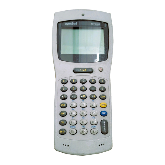
Page 15: Parts Of The Pdt 6100 Series Terminal
PDT 6100 Product Reference Guide Parts of the PDT 6100 Series Terminal Back View Front View Scan Head Scan LED Scanner Display Spectrum 24 Status LED Scan Triggers Charging LED Power Button Scan Bar Battery Compartment Latch Keyboard Top View... -
Page 16: Accessories
The following accessories are available for the PDT 6100 terminal. Battery Chargers PDT 6100 Series terminals use rechargeable Nickel Metal Hydride (NiMH) battery packs. NiMH batteries are charged using one of the charging accessories listed below. Table 1-1. Battery Charging Accessories... -
Page 17: Radio And Network Options
PDT 6100 Product Reference Guide Radio and Network Options Spectrum One ® Network The PDT 6110 includes an internal radio frequency transmitter/receiver for use in a Symbol Spectrum One network. Spectrum24 ® Network The PDT 6142 and PDT 6146 include an internal radio frequency transmitter/receiver for use in a Symbol Spectrum24 network. -
Page 18: Load The Appropriate Software
Getting Started Load the Appropriate Software What software you load and how you load it depends on several factors: If this unit is intended for use in batch applications (6100) or in a Spectrum One network environment (PDT 6110), refer to Chapter 3, Batch and Spectrum One Terminal Setup for information on loading the software. - Page 19 PDT 6100 Product Reference Guide...
-
Page 20: Chapter 2. Installing The Hardware
Chapter 2 Installing the Hardware Introduction The CRD 6100 cradle is used for RS-232 communications, charging, and storing the PDT 6100 terminal. This chapter provides information on setting up the cradle for charging the NiMH battery and communicating with a host or other serial device. Required Parts and Accessories Verify that you have the following cradle parts, cables, and other kits/accessories before attempting to mount or connect the cradle:... -
Page 21: Parts Of The Cradle
PDT 6100 Product Reference Guide Parts of the Cradle Spare Battery Charging Slot Terminal Slot RJ41 Connector Spare Battery Charging Slot Communications Spare Battery Charging LED Modem Connector Front View (available as an option) AC Power DB-25 Connector Communications Port Back View Figure 2-1. -
Page 22: Connecting The Cables
Installing the Hardware Connecting the Cables To connect the CRD 61XX communications cables and power supply: RJ-11 Modem Port Power Jack Serial Cable Figure 2-2. Connecting the Cables 1. Plug the RS-232 serial cable in the communications port located on the back of the cradle. -
Page 23: Connecting To The Telephone Network
PDT 6100 Product Reference Guide To connect the internal modem: 1. Connect the phone cord into the RJ-11 port on the back of the cradle. 2. Connect the other end of the phone cord into the wall phone jack. Caution When connecting the internal modem to the phone line, always connect the phone line to the cradle first, then to the wall phone jack. -
Page 24: Chapter 3. Batch And Spectrum One Terminal Setup
Chapter 3 Batch and Spectrum One Terminal Setup Introduction Before using the PDT 6100 system, perform the following procedures: Set up the CRD 6100 cradle (refer to Chapter 2, Installing the Hardware) Install the battery (refer to Chapter 6, Maintaining the Terminal) Charge the battery (refer to Chapter 6, Maintaining the... -
Page 25: Communications
PDT 6100 Product Reference Guide Communications For terminals being used in a direct communications (batch) environment or a Spectrum One network environment, applications are transferred from a host computer over a communications line to the terminal. This procedure uses the SENDHEX program on the host computer and the Program Loader function (from Command Mode) on the PDT 6100. -
Page 26: Loading An Application
Batch and Spectrum One Terminal Setup Loading an Application To download an application, initiate the communications software on the host computer and PDT 6100. Note: To cancel communications at any time during the session, press CLEAR on the PDT 6100. The session stops immediately. Communication parameters specified on host and PDT 6100 must match. -
Page 27: Initiate Terminal Communications
PDT 6100 Product Reference Guide Note: Versions of SENDHEX earlier than 3.0 do not support flow control. If you use an earlier version and encounter communication errors, use a lower baud rate. If you use a later version of SENDHEX and have communications errors, try setting flow control to XON/XOFF. - Page 28 Batch and Spectrum One Terminal Setup 2. Scroll through Command Mode options using UpArrow or DownArrow until “Program loader” is displayed. Press <ENTER>. 3. The PDT 6100 displays: Program loader WARNING: NVM WILL BE ERASED CONTINUE? <ENT> Before loading the new application, erase NVM’s original contents. Note: To cancel this operation, press <CLEAR>.
-
Page 29: Starting Communications
PDT 6100 Product Reference Guide 7. Parity. If 7 data bits is selected, the PDT 6100 displays: Comm Parameters Parity Press the first letter of a parity option (Even, Odd, None, Space, or Mark), or scroll using UpArrow and DownArrow and press <ENTER> when the correct value is displayed. -
Page 30: Ending Communications
Batch and Spectrum One Terminal Setup 2. Press <ENTER> on the host computer. SENDHEX begins transmitting the program image. When communications are established, the PDT 6100 displays: Program loader Receiving: XXXX where XXXX is the program segment address being transferred. 3. - Page 31 PDT 6100 Product Reference Guide...
-
Page 32: Chapter 4. Spectrum24 Rf Terminal Setup
Chapter 4 ® Spectrum24 RF Terminal Setup Spectrum24 Terminals In Spectrum24 terminals, wireless connectivity is accomplished using standard communications protocols. Because they are standard, the protocols are generalized and take up considerably more space on the terminal’s NVM than is required for Spectrum One ®... -
Page 33: Standard Spectrum24 Software
If your requirements are more advanced, refer to the Spectrum24 Network Terminal Technical Reference Guide (p/n 70-20193-XX) for more information on the Spectrum24 RF network, SLAODI.COM, the Symbol-provided ODI driver, and the configuration file setups required for various platforms. Refer to the Spectrum24 Terminal Setup and Utilities Reference Guide (p/n 72-50795-XX) for more information on Spectrum24 boot options, addressing, initializing the terminal, and Access Point (AP) associations. -
Page 34: Chapter 5. Operating The Pdt 6100 Series
Chapter 5 Operating the PDT 6100 Series Introduction This chapter describes how to operate a PDT 6100 terminal, including: Powering the terminal on/off Booting the terminal Adjusting the display’s contrast Entering data using the keyboard Entering data through the integrated scanner... -
Page 35: Powering A Terminal On And Off
PDT 6100 Product Reference Guide Powering a Terminal On and Off Because the terminal is battery powered, it is important to save power whenever possible. You can minimize power loss and increase battery life by turning the terminal off when data is not being entered. -
Page 36: Forcing Power Off
Operating the PDT 6100 Series Forcing Power Off If a terminal freezes in the middle of operation and pressing < > (PWR) does not power it off, you can force the system to power off, which reduces the drain on the batteries until you can download any collected data to the host system. -
Page 37: Booting The Terminal
PDT 6100 Product Reference Guide Booting the Terminal Powering the terminal on does not boot the system or initialize the program or data. To initialize the terminal, perform either a warm or cold boot. Warm Boot A warm boot resets the operating system while preserving the program and data on the RAM disk. -
Page 38: Cold Boot
Operating the PDT 6100 Series Cold Boot A cold boot fully resets the system and clears memory, including the RAM disk. Any programs and data stored in memory or on the RAM disk are deleted. Nonvolatile memory (NVM — the Application EEPROM) is not affected. If the cold-boot procedure fails to restart... -
Page 39: Cold-Boot Failure
If such a failure occurs, try cold booting the terminal again. If this does not solve the problem, call the Symbol Support Center. More troubleshooting information is provided in the publications listed in... -
Page 40: Adjusting The Display
Operating the PDT 6100 Series For the 46-Key terminal: " Power the terminal off " Press and hold <F> and <I>. " Press and release <PWR>. " Release <F> and <I>. Adjusting the Display Backlighting The terminal’s backlight illuminates the display in dimly lit areas. -
Page 41: Pdt 6100 Series Keyboard
PDT 6100 Product Reference Guide PDT 6100 Series Keyboard The keyboard is used for entering data and issuing commands to the terminal. Figure 5-1, Figure 5-2, and Figure 5-3 illustrate the standard 22-key, 35-key, and 46-key keyboards respectively. Refer to Appendix B, Keyboard Layouts for more information. - Page 42 Operating the PDT 6100 Series Figure 5-2. PDT 6100 Standard 35-Key Keyboard SCAN ENTER Figure 5-3. PDT 6100 Standard 46-Key Keyboard...
-
Page 43: Key Descriptions
PDT 6100 Product Reference Guide Modifier Keys The Shift, Alpha, Function, and Control keys are modifier keys. When pressed individually or in certain combinations, these keys change the keyboard state and possibly the character produced by the character key subsequently pressed. For example: Pressing <Alpha>... - Page 44 Operating the PDT 6100 Series Table 5-1. Special Keys 22-Key 35-Key 46-Key Description Key Name Key Name Key Name CTRL Invokes the control command. (Control) (Control) FUNC FUNC FUNC Invokes the function command for certain utilities, (Function) (Function) such as turning on the back light.
-
Page 45: Scanning
PDT 6100 Product Reference Guide Scanning Before scanning can occur, the application must implement routines to support bar code scanning. For information on scanning applications and on programming the scanner, refer to the Series 3000 Application Development Kit. The PDT 6100 terminal supports an integrated 1-D standard scanning device. Setting the Trigger The integrated scanner has a unique trigger that the operator can configure. -
Page 46: Using The Integrated Laser Scanner
3. Point the PDT 6100 at the bar code and press the scan bar or a side trigger. Figure 5-5. Scanning a Bar Code 4. Ensure that the scan beam crosses all bars and spaces on the symbol, as shown below. Right Wrong 5. -
Page 47: Aiming: Hold At An Angle
PDT 6100 Product Reference Guide Aiming: Hold at an Angle Do not hold the 6100’s scan window directly over the bar code. Laser light reflecting directly back into the scan window from the bar code is known as specular reflection. This strong light can “blind”... - Page 48 7.5 mil 38.1 100% UPC 13.0 20 mil 20.0 40 mil 25.0 55 mil 26.0 12.7 25.4 38.1 50.8 63.5 76.2 Depth of Field Minimum distance determined by symbol length and scan angle Figure 5-7. PDT 6100 Decode Zone 5-15...
-
Page 49: Running Communications
PDT 6100 Product Reference Guide Running Communications Communicating with a Host The 6100 communicates with a host or printer through the CRD 6100 or the Charging and Communications Cable (CCC). To communicate with a host or printer through the CRD 6100: 1. -
Page 50: Radio Communications
Host PC (shown) or Printer Radio Communications The PDT 6110 operates in a Symbol Spectrum One RF network; the PDT 6140 operates in a Symbol Spectrum24 RF network. The Status LED indicates the state of the 6100’s connection to either of the RF networks: indicates that the radio is working and associated with an access point (Spectrum24) or base station (Spectrum One). -
Page 51: Communicating With A Printer
PDT 6100 Product Reference Guide Communicating With a Printer To connect the terminal to a printer, use the CCC or the appropriate printer cable. The following directions apply to the CCC: 1. Plug the CCC’s 10-pin RJ-41 connector into the PDT 6100 terminal’s serial port (refer to Figure 5-9). -
Page 52: Chapter 6. Maintaining The Terminal
Chapter 6 Maintaining the Terminal Batteries The PDT 6100 terminal’s primary power is provided by a nickel metal hydride (NiMH) battery pack. Battery Life Many factors affect battery pack life, including temperature, battery age, and data collection method. Uses and operating conditions which affect battery life are: scanning “power save”... -
Page 53: When To Replace Or Recharge Batteries
PDT 6100 Product Reference Guide Table 6-1. Battery Life: PDT 6100 Battery Type Input Method Approx. Operating Approx. Operating Approx. Operating Time: PDT 6100 Time: PDT 6110 Time: PDT 614X 1500 mAh NiMH Keyboard 50 hours 45 hours 48 hours Laser Scanner 6400 + scans 6100 + scans... -
Page 54: Replacement Batteries
15 minutes while batteries are replaced. The supercap does not provide enough power to operate the terminal. On receiving a low battery message, replace or recharge the primary batteries immediately. Replacement Batteries A rechargeable 1500 mAh NiMH battery pack, p/n 21-33061-01, can be ordered from Symbol Technologies. -
Page 55: Installing A New Or Recharged Battery Pack
PDT 6100 Product Reference Guide Installing a New or Recharged Battery Pack To install a new or recharged NiMH battery: 1. Turn the battery pack latch counterclockwise and remove the battery compartment door. Figure 6-1. Removing the Battery Compartment Door 2. -
Page 56: Charging The Battery
Maintaining the Terminal 4. Replace the battery compartment door (Figure 6-3). Figure 6-3. Replacing the Battery Compartment Door 5. Turn the latch clockwise to secure the battery. Charging the Battery Using the CRD 6100 To charge the NiMH battery in the PDT 6100: 1. - Page 57 PDT 6100 Product Reference Guide Using the CCC The optional CCC provides power from a wall-mounted power supply for recharging the NiMH battery while the 6100 is in use. To connect the 6100 and the CCC: 1. Plug the CCC’s 10-pin RJ41 connector in the 6100’s base. 2.
-
Page 58: Recharging A Spare Battery Pack
Maintaining the Terminal Recharging a Spare Battery Pack To recharge a spare battery pack in the cradle: 1. Insert the battery pack sideways, contacts down, into the spare battery slot, with the tab facing either the right or left side of the cradle. 2. -
Page 59: Cleaning
PDT 6100 Product Reference Guide Battery Charging Tips For maximum capacity and battery life: Charge at temperatures between 0 C and 40 C (32 F and 104 F). Optimum charging occurs at room temperature (about 20 C to 25 C). Above or below that range, batteries may not charge to rated capacity. - Page 60 Maintaining the Terminal to a host computer before removing the primary batteries for longer than 15 minutes. When you remove the terminal from storage without the battery pack, reset the real time clock. Refer to the Series 3000 Application Programmer’s Reference Manual or Series 3000 Application Programmer’s Guide for specific instructions.
- Page 61 PDT 6100 Product Reference Guide 6-10...
-
Page 62: Chapter 7. Error Recovery And Troubleshooting
Chapter 7 Error Recovery and Troubleshooting Introduction This chapter provides information to assist in basic trouble analysis and correction for the PDT 6100, including: Error messages Troubleshooting start-up failures Troubleshooting Spectrum24 terminal initialization failures Running the self test function Self test summaries Keyboard test Running memory transfer Scanning problems. -
Page 63: Troubleshooting
PDT 6100 Product Reference Guide Table 7-1. Error Messages Message Explanation Double Key Error Two or more keys were pressed at the same time. This does not include boot sequences (refer to Chapter 5, Operating the PDT 6100 Series, for boot sequences). Low Battery The battery pack should be recharged or replaced as soon as possible. -
Page 64: Spectrum24 Terminal
If the system halts at one of these lines and displays a status value other than 0, the displayed device driver did not load properly. If such a failure occurs, cold boot the terminal again. If this does not solve the problem, call Symbol Customer Support. More troubleshooting information is found in the documentation listed in Related Publications. -
Page 65: Self Test Function
Running the Self Test Access the Self Test function from the Command Mode menu: 1. Boot to command mode (refer to Chapter 5, Operating the PDT 6100 Series for boot sequences). 2. On the Command Mode screen, use the <UpArrow> or <DownArrow> to scroll through the options. -
Page 66: Keyboard Test
Error Recovery and Troubleshooting Keyboard Test Keyboard testing can be performed while the terminal displays Config Screen 1 results. Test any keys except Clear and PWR. When you press a key, the corresponding key code is displayed on the top row to the right of the test name. Table 7-3, Table... - Page 67 PDT 6100 Product Reference Guide Table 7-4. 35-Key Keyboard Test Codes Test Code Test Code Alpha Space Shift Func Ctrl Backspace Enter...
- Page 68 Error Recovery and Troubleshooting Table 7-5. 46-Key Keyboard Test Codes Test Code Test Code CONTROL SHIFT Up Arrow Down Arrow BKSP SPACE FUNC ENTER...
-
Page 69: Exiting Self Test
PDT 6100 Product Reference Guide Exiting Self Test The test loop continues updating the time and battery status and processing keystrokes. To end the test, press <Clear>.The display returns to the Command Mode menu. Memory Transfer Program Command Mode includes a memory transfer utility that transfers data from a terminal to a host PC for program troubleshooting. -
Page 70: Set Communications Parameters
Error Recovery and Troubleshooting 3. Connect the host to the CRD 6100: a. Plug the null modem’s connector in the cradle’s communications port. b. Plug the other connector in the host’s communications port. c. Place the terminal in the cradle. 4. - Page 71 PDT 6100 Product Reference Guide Terminal 1. Boot the terminal to Command Mode (refer to Chapter 5, Operating the PDT 6100 Series for the appropriate key sequence). 2. Select the Memory Transfer function from the Command Mode menu. Use <UpArrow> or <DownArrow> to scroll through the command mode options until Memory Transfer is displayed, and press <Enter>.
- Page 72 Error Recovery and Troubleshooting 7. The terminal displays a range verification screen. For example: RAM 0000 3FFF NVM C839 DFFF None Correct? If the values are correct, press <Enter>. If the values are not correct, press <Clear> to clear the fields and select new values. 8.
-
Page 73: Internal Modem Problems
Check the bar code to make sure it is not defaced. A defaced 1-D bar code may not be readable by any scanner. Check to see if you are scanning from the proper distance. Try scanning a test symbol of the symbology you are trying to read. 7-12... - Page 74 Error Recovery and Troubleshooting Your terminal operates but scanned data is not displayed correctly? Check the system power. Check that the communication parameters (baud rate, parity, stop bits, etc.) are set properly for the receiving device. The laser does not activate? You may have exceeded the allowable amount of scanning activity within the limits of your laser class of operation;...
- Page 75 PDT 6100 Product Reference Guide 7-14...
-
Page 76: Appendix A Port Pin-Outs
Appendix A Port Pin-Outs Introduction This appendix provides reference information for PDT 6100 ports and mappings for a null modem cable. Pinouts for PDT 6100 Serial Devices The RJ41 connector is located in the base of the terminal. Table A-1. RJ-41 Connector Pin# Signal Description... - Page 77 PDT 6100 Product Reference Guide...
-
Page 78: Appendix B Keyboard Layouts
Appendix B Keyboard Layouts Introduction The following pages show the characters, scan codes, ASCII values, and character key sequences produced by the different PDT 6100 keyboards when modified with the ap- propriate key sequence. As explained in Chapter 5, these key definitions can be changed by the application pro- gram. -
Page 79: 22-Key Keyboard
PDT 6100 Product Reference Guide 22-Key Keyboard SCAN SCAN 77 00 97 00 FUNC BACK FUNC BACK 78 43 12 45 SEND 22-Key Keyboard 22-Key Unmodified Keyboard SCAN 100 00 BACK- FUNC LIGHT 102 00 LIGHTER SCREEN 65 00 66 00 101 00 DARKER SCREEN... -
Page 80: 35-Key Keyboard
Keyboard Layouts 35-Key Keyboard 35-Key Keyboard 26 91 27 93 40 39 13 61 55 42 53 47 51 44 43 92 39 59 78 43 75 00 77 00 72 00 80 00 57 32 10 57 58 00 35-Key Unmodified Keyboard 42 00 97 00... - Page 81 PDT 6100 Product Reference Guide 30 65 48 66 46 67 32 68 18 69 33 70 34 71 35 72 23 73 36 74 37 75 38 76 50 77 49 78 57 32 24 79 25 80 16 81 58 00 35-Key Alpha Key Modified Keyboard 42 00...
- Page 82 Keyboard Layouts 30 1 48 2 46 3 32 4 18 5 33 6 34 7 35 8 23 9 36 10 35-Key Control Key Modified Keyboard 37 11 38 12 50 13 49 14 57 32 24 15 25 16 16 77 58 00 42 00...
- Page 83 PDT 6100 Product Reference Guide 30 00 48 00 46 00 32 00 18 00 33 00 34 00 35 00 23 00 36 00 37 00 38 00 50 00 49 00 57 32 24 00 25 00 16 00 58 00 35-Key Alt Key Modified Keyboard 42 00...
- Page 84 Keyboard Layouts 119 00 132 00 118 00 100 00 101 00 102 00 58 00 35-Key Ctrl + Func Modified Keyboard 42 00 97 00 98 00 99 00 97 00 56 00 94 00 95 00 96 00 103 00 110 00 111 00...
-
Page 85: 46-Key Keyboard
PDT 6100 Product Reference Guide 46-Key Keyboard SCAN 46-Key Keyboard ENTER SCAN 29 00 30 97 48 98 46 99 32 100 01 27 18 101 33 102 34 103 35 104 23 105 36 106 37 107 38 108 50 109 49 110 46-Key Unmodified Keyboard... - Page 86 Keyboard Layouts SCAN 46-Key Shift Modified Keyboard 29 00 30 65 48 66 46 67 01 27 & 42 00 14 08 72 56 80 50 > ENTER SCAN 29 00 30 65 48 66 46 67 01 27 46-Key Caplock Modified Keyboard 42 00 14 08 72 00...
- Page 87 PDT 6100 Product Reference Guide SCAN 29 00 30 01 48 02 46 03 01 27 46-Key Control Modified Keyboard Ctrl A Ctrl B Ctrl C Ctrl D Ctrl E Ctrl G Ctrl F Ctrl H Ctrl K Ctrl I Ctrl J Ctrl L Ctrl M...
- Page 88 Keyboard Layouts SCAN 46-Key Shift + Func Modified Keyboard 13 43 74 45 01 27 41 126 43 124 26 123 27 125 BACK LIGHT < " DARKER LIGHTER SCREEN SCREEN Shift F7 Shift F8 Shift F9 Shift F5 Shift F6 Shift F4 57 32 SPACE...
- Page 89 PDT 6100 Product Reference Guide SCAN 46-Key Control + Func Modified 55 00 1 27 Keyboard Ctrl * Ctrl E Ctrl G Ctrl F BACK LIGHT Ctrl \ Ctrl - Ctrl [ Ctrl ] CtrlEnd CtrlHm DARKER LIGHTER Ctrl SCREEN SCREEN Pgup Ctrl Z...
-
Page 90: Appendix C Communications Status Codes
Appendix C Communications Status Codes Introduction The program loader status code consists of four hexadecimal digits which indicate whether or not the transfer was successful, and if not, the source of the communications error. A status code of 0000 indicates success; any other code indicates failure. Table C-1 lists the failures associated with the status codes. - Page 91 PDT 6100 Product Reference Guide Table C-1. Communications Status Codes Status Code Meaning 0002 Receive overrun error 0004 Receive parity error 0008 Receive framing error 0010 Programming voltage not present 0020 Data Set Ready or Carrier Detect not detected on open 0040 Lost DSR while receiving 0080...
-
Page 92: Appendix D Specifications
Appendix D Specifications Environment The terminal’s operating conditions are listed in Table Table D-1. Table D-1. Environmental Specifications Condition Range Operating Temperature -4° to 122°F 0° to 40°C Storage Temperature -40° to 158°F -40° to 60°C Humidity (Operating) 5% to 95% non-condensing @ 50°C for 168 hours Altitude Up to 10,000 feet... - Page 93 PDT 6100 Product Reference Guide...
-
Page 94: Glossary
A pattern of variable-width bars and spaces which represents numeric or alphanumeric data in machine-readable form. The general format of a bar code symbol consists of a leading margin, start character, data or message character, check character (if any), stop character, and trailing margin. Within this framework, each recognizable symbology uses its own unique format. - Page 95 0 to 9 and six additional characters: (- $ : / , +). Code 128 A high density symbology which allows the controller to encode all 128 ASCII characters without adding extra symbol elements. Code 3 of 9 (Code 39) A versatile and widely used alphanumeric bar code symbology with a set of 43 character types, including all uppercase letters, numerals from 0 to 9, and 7 special characters (- .
- Page 96 Glossary Development Kits A set of software tools provided to customers to help them create applications for their terminals. See ADK. Discrete 2 of 5 A binary bar code symbology representing each character by a group of five bars, two of which are wide. The location of wide bars in the group determines which character is encoded;...
- Page 97 PDT 6100 Product Reference Guide IOCTL Input/Output Control. Internet Protocol. Local Area Network. Refer to Liquid Crystal Display. Refer to Light Emitting Diode. Light Emitting Diode A low power electronic light source commonly used as an (LED) indicator light. Uses less power than incandescent light bulb but more than a Liquid Crystal Display (LCD).
- Page 98 Photodetector - registers the difference in reflected light (more light reflected from spaces). Signal conditioning circuit - transforms optical detector output into a digitized bar pattern. SE 900 Symbol's miniature laser scan modules that can be integrated into portable computing devices. SHIP Symbol Host Interface Program. Spectrum24 Symbol’s frequency-hopping, spread spectrum cellular network.
- Page 99 PDT 6100 Product Reference Guide Terminate and Stay A program under DOS that ends its foreground execution to Resident (TSR) remain resident in memory to service hardware/software interrupts, providing background operation. It remains in memory and may provide services on behalf of other DOS programs. Transmission Control A suite of the standard network protocols that were originally Protocol/Internet Protocol...
-
Page 100: Index
Index ALT key ......5-10 Numerics 22-key keyboard ..... B-2 22-key test codes . - Page 101 PDT 6100 Product Reference Guide to Command Mode ....5-6 single-slot ..... . . 1-3 warm .
- Page 102 Index application storage ....4-1 selecting a range ....7-10 configuration file storage .
- Page 103 ..... . . 5-12 symbol support center ....ix scanners system software, Spectrum24 .
- Page 104 Index troubleshooting ..... 7-2 applications ..... 7-8 terminal memory transfer .
- Page 105 PDT 6100 Product Reference Guide Index-6...
- Page 106 We’d like to know what you think about this Manual. Please take a moment to fill out this questionnaire and fax this form to: (631) 738-3318, or mail Symbol Technologies, Inc. One Symbol Plaza M/S B-4 Holtsville, NY 11742-1300 Attn: Technical Publications Manager IMPORTANT: If you need product support, please call the appropriate cus- tomer support number provided.
- Page 108 PDT 6100 Series Product Reference Guide 70-33222-02 Revision A — June 2001 Symbol Technologies, Inc. One Symbol Plaza, Holtsville N.Y. 11742-1300...