Table of Contents
Advertisement
Quick Links
RETURN TO MAIN INDEX
SVM 110-A
January, 1996
TM
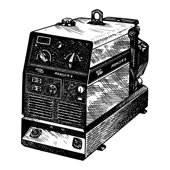
RANGER 9
For use with machine code numbers 9975 and 9976
Safety Depends on You
Lincoln arc welding and cutting
equipment is designed and built
with safety in mind. However,
your overall safety can be
increased by proper installation .
. . and thoughtful operation on
your part. DO NOT INSTALL,
OPERATE OR REPAIR THIS
EQUIPMENT WITHOUT READ-
ING THIS MANUAL AND THE
SAFETY PRECAUTIONS CON-
TAINED THROUGHOUT. And,
most importantly, think before
you act and be careful.
SERVICE MANUAL
World's Leader in Welding and Cutting Products
Premier Manufacturer of Industrial Motors
Sales and Service through subsidiaries and Distributors Worldwide
22801 St. Clair Ave. Cleveland, Ohio 44117-1199 U.S.A. Tel. (216) 481-8100
Advertisement
Chapters
Table of Contents
Troubleshooting

Related Manuals for Lincoln Electric RANGER 9 SVM 110-A


Summary of Contents for Lincoln Electric RANGER 9 SVM 110-A
-
Page 1: Service Manual
RETURN TO MAIN INDEX SVM 110-A January, 1996 RANGER 9 For use with machine code numbers 9975 and 9976 Safety Depends on You Lincoln arc welding and cutting equipment is designed and built with safety in mind. However, your overall safety can be increased by proper installation . -
Page 2: Safety
Miami, Florida 33135 or CSA Standard W117.2-1974. A Free copy of “Arc Welding Safety” booklet E205 is available from the Lincoln Electric Company, 22801 St. Clair Avenue, Cleveland, Ohio 44117-1199. BE SURE THAT ALL INSTALLATION, OPERATION, MAINTENANCE AND REPAIR PROCEDURES ARE PERFORMED ONLY BY QUALIFIED INDIVIDUALS. -
Page 3: Electric Shock Can Kill
ELECTRIC SHOCK can kill. 3.a. The electrode and work (or ground) circuits are electrically “hot” when the welder is on. Do not touch these “hot” parts with your bare skin or wet clothing. Wear dry, hole-free gloves to insulate hands. - Page 4 WELDING SPARKS can cause fire or explosion. 6.a. Remove fire hazards from the welding area. If this is not possible, cover them to prevent the welding sparks from starting a fire. Remember that welding sparks and hot materials from welding can easily go through small cracks and openings to adjacent areas.
- Page 5 PRÉCAUTIONS DE SÛRETÉ Pour votre propre protection lire et observer toutes les instructions et les précautions de sûreté specifiques qui parraissent dans ce manuel aussi bien que les précautions de sûreté générales suiv- antes: Sûreté Pour Soudage A L’Arc 1. Protegez-vous contre la secousse électrique: a.
-
Page 6: Table Of Contents
MASTER TABLE OF CONTENTS FOR ALL SECTIONS Safety...i-iv Installation ...Section A Installation Section Table of Contents ...A-1 Technical Specifications ...A-2 Safety Precautions...A-3 Location and Ventilation ...A-3 Pre-operation Engine Service ...A-4 Electrical Output Connections...A-5 Operation...Section B Safety Instructions ...B-2 General Description ...B-2 Recommended Applications ...B-3 Operational Features and Controls ...B-3 Design Features and Advantages...B-3... - Page 7 Section A-1 - INSTALLATION SECTION - Installation Technical Specifications ...A-2 Safety Precautions...A-3 Location and Ventilation ...A-3 Storing ...A-3 Stacking...A-4 Tilting ...A-4 Lifting ...A-4 High Altitude Operation...A-4 Pre-operation Engine Service ...A-4 Oil ...A-4 Fuel ...A-4 Battery Connections...A-4 Muffler Relocation ...A-5 Spark Arrester ...A-5 Electrical Output Connections...A-5 Welding Cable Connections ...A-6 Cable Size and Length ...A-6...
-
Page 8: Installation
18 HP @ 3600 RPM RATED OUTPUT - WELDER Duty Cycle 100% Duty Cycle 100% Duty Cycle 100% Duty Cycle OUTPUT - WELDER AND GENERATOR Welding Ranges Max. Open Circuit Voltage 40 - 250 Amps 80 Volts RMS @ 3700 RPM Height With Onan Engine: 30.3 in. -
Page 9: Safety Precautions
Read this entire installation section before you start installation. SAFETY PRECAUTIONS WARNING Do not attempt to use this equipment until you have thoroughly read all the operation and maintenance manuals supplied with your machine. They include important safety precautions; detailed engine starting, operating, and maintenance instructions;... -
Page 10: Pre-Operation Engine Service
STACKING RANGER 9 machines CANNOT be stacked. TILTING Place the machine on a secure, level surface whenev- er you use it or store it. Any surfaces you place it on other than the ground must be firm, non-skid, and structurally sound. The gasoline engine is designed to run in a level posi- tion for best performance. -
Page 11: Electrical Output Connections
RANGER 9 INSTALLATION 1. OUTPUT RANGE SELECTOR 2. FINE OUTPUT CONTROL 3. CONTROL AT WELDER/REMOTE CONTROL SWITCH 4. WELDING TERMINALS SWITCH CHOKE 5. POLARITY SWITCH 6. 115/230 VOLT, 50 AMP RECEPTACLE AUTO START 7. -
Page 12: Welding Cable Connections
2 AWG 1 AWG 1 AWG 1/0 AWG Lincoln Electric offers a welding accessory kit with the properly specified welding cables. See the Acces- sories section of this manual for more information. For more information on welding, see WELDING OPERATION and SUMMARY OF WELDING PRO- CESSES in the Operations section of this manual. -
Page 13: Auxiliary Power Receptacles, Plugs, And Hand-Held Equipment
When the RANGER 9 is mounted on a truck or a trailer, the machine generator ground stud MUST be securely connect- ed to the metal frame of the vehicle. See Figure A.1. The ground stud is marked with the ground symbol. If the RANGER 9 is connected to premises wiring such as a home or shop, it must be properly connected to the system earth ground. - Page 14 FIGURE A.2 - CONNECTION OF RANGER 9 TO PREMISES WIRING 230 VOLT 230 Volt POWER 60 Hz. COMPANY 3-Wire METER Service DOUBLE POLE DOUBLE THROW SWITCH RATING TO BE THE SAME AS OR GREATER THAN PREMISES SERVICE OVERCURRENT PROTECTION. 50 AMP, 115/230 VOLT PLUG NEMA TYPE 14-50 50 AMP, 115/230 VOLT...
-
Page 15: Recommended Applications
Operational Features and Controls ...B-3 Design Features and Advantages...B-3 Welding Capability ...B-4 Limitations ...B-4 Controls and Settings ...B-4 Welder/Generator Controls ...B-5 Gasoline Engine Controls...B-7 Engine Operation ...B-7 Before Starting the Engine ...B-8 Starting the Engine ...B-8 Stopping the Engine ...B-8 Break-in Period ...B-8... -
Page 16: Operation
60 Hz, single-phase AC power to operate AC power tools, battery chargers, and lighting; it can also be used to provide standby power. As a welder it pro- vides 250 amps of AC current for welding with AC stick electrodes or 250 amps of DC current for DC stick welding. -
Page 17: Recommended Applications
AC/DC welding output for stick (SMAW) welding and for TIG welding, and it offers constant voltage output for DC semiautomatic wire feed welding. For more details on using the machine as a welder, see WELD- ING OPERATION in the Operation section of this manual. -
Page 18: Welding Capability
CONTROLS AND SETTINGS All generator/welder controls are located on the Output Control Panel of the machine case front. Gasoline engine choke control, idler control, and start/stop controls are also on the case front. See Figure B.1 and the explanations that follow. -
Page 19: Welder/Generator Controls
RANGER 9 OPERATION 1. OUTPUT RANGE SELECTOR 2. FINE OUTPUT CONTROL 3. POLARITY SWITCH 4. CONTROL AT WELDER/REMOTE CONTROL SWITCH 5. WELDING TERMINALS ALWAYS ON/ WELDING TERMINALS REMOTELY CONTROLLED SWITCH AUTO START IDLER 6 WIRE FEEDER POWER CIRCUIT BREAKER... - Page 20 7. 20 AMP, 115 VOLT DUPLEX RECEPTACLES: Connection point for supplying 115 volt power to operate one or two electrical devices. 8. 50 AMP, 230 VOLT RECEPTACLE: Connection point for supplying 230 volt power to operate one electrical device. 9. WELD OUTPUT TERMINAL (TO WORK) WITH FLANGE NUT: Provides the connection point for the work cable.
-
Page 21: Engine Operation
FIGURE B.2 – GASOLINE ENGINE CONTROLS 1. ENGINE CHOKE CONTROL 2. IDLER CONTROL SWITCH 3. START/STOP SWITCH 4. ENGINE HOUR METER 5. BATTERY CHARGING SYSTEM METER GASOLINE ENGINE CONTROLS See Figure B.2 for the location of the following fea- tures: 1. -
Page 22: Before Starting The Engine
BEFORE STARTING THE ENGINE Check and fill the engine oil level: 1. Be sure the machine is on a level surface. 2. Remove the engine oil dipstick and wipe it with a clean cloth. Reinsert the dipstick and check the level on the dipstick. - Page 23 TYPICAL RANGER 9 FUEL CONSUMPTION Low Idle – No Load, 2150 RPM High Idle – No Load, 3700 RPM AC CC Weld Output, 250 Amps @ 25 Volts DC CC Weld Output, 250 Amps @ 25 Volts DC CV Weld Output, 250 Amps @ 25 Volts Auxiliary Power, 9000 kVA RANGER 9 OPERATION...
-
Page 24: Welding Operation
B-10 WELDING OPERATION GENERAL INFORMATION WARNING • Do not touch electrically live parts or elec- trodes with your skin or wet clothing. • Do not breathe welding fumes or gases. • Use ventilation or exhaust to remove welding fumes from the breathing area. •... -
Page 25: Ac/Dc Tig (Constant Current) Welding
B-11 To Use the RANGER 9 for AC/DC TIG (Constant Current) Welding: 1. Connect the K930-1 TIG Module to the RANGER Follow the installation instructions provided with the kit. Also be sure to follow the special machine grounding instructions given in the man- ual. - Page 26 B-12 To Use the RANGER 9 for DC Wire Feed Welding (Constant Voltage): 1. Connect one of the following: the LN-25, LN-7, LN-8, or LN-742 Wire Feeder. Follow the installa- tion instructions in the ACCESSORIES section of this manual. 2. Some recommended Innershield electrodes are: NR-211MP, NR-311, NR-203 series, as well as Lincore ®...
-
Page 27: Summary Of Welding Processes
LN-742 Wire Feed - CV, High LN-7 RANGER 9 OPERATION Output Welding Electrode Control Terminals State When Switch Switch Not Welding At Welder Always on Remote Remote Cold Remote Remote Cold At Welder Always on Cold Remote Remote Cold Remote... -
Page 28: Auxiliary Power
B-14 AUXILIARY POWER WARNING Be sure that any electrical equipment plugged into the generator AC power receptacles can withstand a ±10% voltage and a ±3% frequency variation. GENERAL INFORMATION The RANGER 9 generator is rated at 9000 continuous watts. It provides both 115 volt and 230 volt power. You can draw up to 80 amps total from the 115 volt receptacles, but no more than 20 amps (15 amps CSA) from each receptacle at once. - Page 29 B-15 TABLE B.5 - SIMULTANEOUS WELDING AND AUXILIARY POWER Output Selector Welding Setting Output CV Low CV Medium CV High RANGER 9 OPERATION Permissible Power in Watts Permissible Auxiliary Current (Unity Power Factor) None 2500 3700 5000 6000 7500 5000 7500 2750 6500...
- Page 30 *Submersible Pump - 1 HP *Sump Pump Toaster Weed Trimmer Lincoln 100 or 125 Amp Wire Feeder/Welder NOTES: Wattages listed are approximate. Check your equipment for actual wattage. Equipment with unusually high *START-UP WATTS are listed. For start-up of other equipment listed in the table, multiply RUNNING WATTS by 2.
- Page 31 Options/Accessories...C-2 TIG Welding...C-3 Semiautomatic FCAW and MIG Welding ...C-3 Connection of Lincoln Electric Wire Feeders...C-4 Connection of the K867 Universal Adapter ...C-4 Connection of the LN-25 “Across the Arc” ...C-5 Connection of the LN-25 with 42V Remote Output Control Module ...C-6 Connection of the LN-7 Using the K584 Input Cable Assembly...C-7...
-
Page 32: Accessories
OPTIONS/ACCESSORIES The following options/accessories are available for your RANGER 9 from your local Lincoln Distributor. Two-Wheel Trailer (K768-2) – For in-plant or yard towing of the RANGER 9. (Not intended for highway towing as equipped. For highway use of this trailer, consult applicable federal, state, and local laws about possible requirements for brakes, lights, fenders, etc. -
Page 33: Tig Welding
TIG WELDING TIG Module (K930-1) - The TIG Module is an acces- sory that provides high frequency and shielding gas control for AC and DC GTAW (TIG) welding applica- tions. It provides contactor control of constant current welding power sources having an internal contactor. The K930-1 TIG Module is supplied without accessories. -
Page 34: Connection Of Lincoln Electric Wire Feeders
WIRE FEEDERS USING K867 UNIVERSAL ADAPTER (SEE FIGURE C.1) NOTE: When you use the RANGER 9 with non- Lincoln Electric wire feeders or with cer- tain earlier models of Lincoln wire feeders, you will require the K867 Univeral Adapter. The following discussion and connection diagram explain in general how to make the proper connections. - Page 35 NOTE: Welding cable must be sized for current and duty cycle of application. 3. Set the welder “polarity” switch to the desired polarity, either DC (-) or DC (+). 4. Set the “RANGE” switch to the “WIRE FEED” posi- tion.
- Page 36 1. Shut the welder off. 2. Connect the electrode cable from the K626-XX Input Cable Assembly to the “ELECTRODE” termi- nal of the welder and to the LN-25 wire feeder. Connect the work cable to the “TO WORK” termi- nal of the welder.
- Page 37 1. Shut the welder off. 2. Connect the electrode cable from the K584-XX Input Cable Assembly to the “ELECTRODE” termi- nal of the welder and to the LN-7 wire feeder. Connect the work cable to the “TO WORK” termi- nal of the welder.
- Page 38 A. Insulate each unused lead individually. B. Splice the leads and insulate. 4. Set the welder “polarity” switch to the desired polarity, either DC (-) or DC (+). 5. Set the “RANGE” switch to the “WIRE FEED” posi- tion.
- Page 39 A. Insulate each unused lead individually. B. Splice the leads and insulate. 4. Set the welder “polarity” switch to the desired polarity, either DC (-) or DC (+). 5. Set the “RANGE” switch to the “WIRE FEED” posi- tion.
- Page 40 3. Connect the K592 Control Cable to the 14 pin amphenol on the RANGER 9 and the input cable plug on the LN-742. 4. Set the welder “polarity” switch to the desired polarity, either DC (-) or DC (+). 5. Set the “RANGE” switch to the “WIRE FEED” posi- tion.
- Page 41 1. Shut the welder off. 2. Connect the electrode cable from the SG Control Module to the “ELECTRODE” terminal of the welder. Connect the work cable to the “TO WORK” terminal of the welder. NOTE: Welding cable must be sized for current and duty cycle of application.
-
Page 42: Routine And Periodic Maintenance
Engine Maintenance Parts ...D-6 Battery Maintenance ...D-7 Cleaning the Battery ...D-7 Checking Specific Gravity...D-7 Checking Electrolyte Level...D-7 Charging the Battery ...D-7 Welder/Generator Maintenance ...D-7 Storage...D-7 Cleaning ...D-7 Brush Removal and Replacement ...D-7 Receptacles ...D-8 Cable Connections...D-8 Major Component Locations ...D-9... -
Page 43: Safety Precautions
SAFETY PRECAUTIONS WARNING • Have qualified personnel do all maintenance and troubleshooting work. • Turn the engine off before working inside the machine. • Remove guards only when necessary to perform maintenance and replace them when the mainte- nance requiring their removal is complete. •... -
Page 44: Change The Oil Filter
FIGURE D.1 – OIL DRAIN AND REFILL LOCATION 1. DIPSTICK/OIL FILL 2. OIL DRAIN PLUG CHANGE THE OIL FILTER Change the oil filter the first time after 25 hours of operation. Then, under normal operating conditions, change the oil filter after every other oil change. If the engine is operated under heavy load or in high ambi- ent temperatures, change the oil filter more frequently. -
Page 45: Air Cleaner
AIR CLEANER: Your air cleaner may have only the paper element, or it may have the cartridge and a foam preclean- er. If it has the precleaner, service the element every 50 hours and the pre- cleaner every 25 hours. If the air cleaner doesn’t have the precleaner, service the element every 25 hours. -
Page 46: Crankcase Breather
CRANKCASE BREATHER: The Onan engine is equipped with a crankcase breather that prevents pressure from building up inside the crankcase, pre- vents moisture contamination from moisture, gasoline vapors, or combustion vapors. If the breather valve becomes sticky, it can cause oil leaks, oil consump- tion, rough idle, reduced power, and sludge and var- nish buildup in the engine. -
Page 47: Engine Maintenance Parts
ONAN ENGINE MAINTENANCE SCHEDULE FREQUENCY MAINTENANCE REQUIRED Daily or Before Starting Engine • Fill fuel tank. • Check oil level. • Check air cleaner for dirty • Check air intake and cooling areas, clean as necessary Every 25 Hours • Service precleaner element Every 50 Hours •... -
Page 48: Battery Maintenance
• CONNECTING A BATTERY CHARGER - Remove the battery from the welder by disconnecting the negative cable first, then the positive cable and battery clamp. When reinstalling, connect the negative cable last. -
Page 49: Brush Removal And Replacement
To reinstall the brushes, press them upward and slide a cable tie or wooden stick through the brush holder tabs. See Figure D.4. Install the brush holder into position and secure with the screws previously removed. Remove the cable tie or wooden stick and the brushes will seat onto the slip rings. -
Page 50: Major Component Locations
FIGURE D.6 - MAJOR COMPONENT LOCATIONS RANGER 9 MAINTENANCE 1. OUTPUT TERMINALS (LOCATION) 2. ENGINE CONTROLS 3. AUXILIARY POWER RECEPTACLES 4. OUTPUT PANEL CONTROL 5. OUTPUT RECTIFIER/REACTOR/CHOKE 6. FUEL TANK FILL 7. GASOLINE ENGINE 8. ROTOR/STATOR ASSEMBLY 9. BATTERY 10. MACHINE BASE 11. - Page 51 Section E-1 -THEORY OF OPERATION SECTION- Theory of Operation ...Section E Battery, Starter, Engine, Rotor, Stator, and Idler Solenoid...E-2 Rotor Field Feedback, Auxiliary, and Wire Feeder Power...E-3 Weld Winding, Reactor, and Range Switch...E-4 Output Bridge, Capacitors, Choke, Polarity Switch, Contactor and Output Terminals...E-5 ENGINE STARTER FLYWHEEL...
-
Page 52: Theory Of Operation
THEORY OF OPERATION FIGURE E.2 – BATTERY, STARTER, ENGINE, ROTOR, STATOR AND IDLER SOLENOID ENGINE STARTER FLYWHEEL ALTERNATOR BATTERY BY-PASS BOARD CONTACTOR CLOSURE OUTPUT CONTROL REMOTE SWITCH 115VAC 42VAC 6 PIN 14 PIN AMPHENOL AMPHENOL BATTERY, STARTER, ENGINE, ROTOR, STATOR, AND IDLER SOLENOID The 12VDC battery powers the starter motor. - Page 53 THEORY OF OPERATION FIGURE E.3 – ROTOR FIELD FEEDBACK, AUXILIARY, AND WIRE FEEDER POWER ENGINE STARTER FLYWHEEL ALTERNATOR BATTERY BY-PASS BOARD CONTACTOR CLOSURE OUTPUT CONTROL REMOTE SWITCH 115VAC 42VAC 6 PIN 14 PIN AMPHENOL AMPHENOL ROTOR FIELD FEEDBACK, AUXILIARY, AND WIRE FEEDER POWER The AC voltage developed in the field winding is fed to the full wave field bridge.
- Page 54 THEORY OF OPERATION FIGURE E.4 – WELD WINDING, REACTOR, AND RANGE SWITCH ENGINE STARTER FLYWHEEL ALTERNATOR BATTERY BY-PASS BOARD CONTACTOR CLOSURE OUTPUT CONTROL REMOTE SWITCH 115VAC 42VAC 6 PIN 14 PIN AMPHENOL AMPHENOL WELD WINDING, REACTOR, AND RANGE SWITCH The stator weld winding is connected to the reactor and range switch.
- Page 55 THEORY OF OPERATION OUTPUT BRIDGE, CAPACITOR, CHOKE, POLARITY SWITCH, CONTACTOR AND OUTPUT TERMINALS ENGINE STARTER FLYWHEEL ALTERNATOR BATTERY BY-PASS BOARD CONTACTOR CLOSURE OUTPUT CONTROL REMOTE SWITCH 115VAC 42VAC 6 PIN 14 PIN AMPHENOL AMPHENOL OUTPUT BRIDGE, CHOKE, POLARITY SWITCH, AND OUTPUT TERMINALS The AC voltage developed in the stator weld winding is delivered, through the reactor and range switch, to...
- Page 56 Section F-1 TROUBLESHOOTING & REPAIR SECTION Troubleshooting & Repair Section ...Section F How to Use Troubleshooting Guide ...F-2 PC Board Troubleshooting Procedures ...F-3 Troubleshooting Guide ...F4 - F-18 Test Procedures Rotor Voltage Test ...F-19 Rotor Resistance Test ...F-21 Auxiliary and Field Winding Test ...F-24 Output Rectifier Bridge Test...F-29 Charging Circuit Test ...F-31 Engine Throttle Adjustment Test ...F-33...
-
Page 57: Troubleshooting & Repair Section
TROUBLESHOOTING & REPAIR HOW TO USE TROUBLESHOOTING GUIDE Service and repair should be performed by only Lincoln Electric Factory Trained Personnel. Unauthorized repairs performed on this equipment may result in danger to the technician and machine operator and will invalidate your factory warranty. For your safety and to avoid Electrical Shock, please observe all safety notes and precautions detailed throughout this manual. -
Page 58: Pc Board Troubleshooting Procedures
• If the PC Board uses protective shorting jumpers, don’t remove them until installation is complete. • If you return a PC Board to The Lincoln Electric Company for credit, it must be in the static-shielding bag. This will prevent further damage and allow proper failure analysis. -
Page 59: Troubleshooting Guide
Engine operates normally. If for any reason you do not understand the test procedures or are unable to perform the test/repairs safely, con- tact the Lincoln Electric Service Department for electrical troubleshooting assistance before you proceed. Call 216-383-2531 or 1-800-833-9353. - Page 60 Engine operates normal- If for any reason you do not understand the test procedures or are unable to perform the test/repairs safely, con- tact the Lincoln Electric Service Department for electrical troubleshooting assistance before you proceed. Call 216-383-2531 or 1-800-833-9353.
- Page 61 If for any reason you do not understand the test procedures or are unable to perform the test/repairs safely, con- tact the Lincoln Electric Service Department for electrical troubleshooting assistance before you proceed. Call 216-383-2531 or 1-800-833-9353. RANGER 9...
- Page 62 If for any reason you do not understand the test procedures or are unable to perform the test/repairs safely, con- tact the Lincoln Electric Service Department for electrical troubleshooting assistance before you proceed. Call 216-383-2531 or 1-800-833-9353.
- Page 63 If for any reason you do not understand the test procedures or are unable to perform the test/repairs safely, con- tact the Lincoln Electric Service Department for electrical troubleshooting assistance before you proceed. Call 216-383-2531 or 1-800-833-9353. RANGER 9...
- Page 64 If for any reason you do not understand the test procedures or are unable to perform the test/repairs safely, con- tact the Lincoln Electric Service Department for electrical troubleshooting assistance before you proceed. Call 216-383-2531 or 1-800-833-9353.
- Page 65 If for any reason you do not understand the test procedures or are unable to perform the test/repairs safely, con- tact the Lincoln Electric Service Department for electrical troubleshooting assistance before you proceed. Call 216-383-2531 or 1-800-833-9353.
- Page 66 “HIGH” position. If for any reason you do not understand the test procedures or are unable to perform the test/repairs safely, con- tact the Lincoln Electric Service Department for electrical troubleshooting assistance before you proceed. Call 216-383-2531 or 1-800-833-9353. RANGER 9 detailed in the beginning of this manual.
-
Page 67: Cable Connections
If for any reason you do not understand the test procedures or are unable to perform the test/repairs safely, con- tact the Lincoln Electric Service Department for electrical troubleshooting assistance before you proceed. Call 216-383-2531 or 1-800-833-9353. RANGER 9 detailed in the beginning of this manual. - Page 68 If for any reason you do not understand the test procedures or are unable to perform the test/repairs safely, con- tact the Lincoln Electric Service Department for electrical troubleshooting assistance before you proceed. Call 216-383-2531 or 1-800-833-9353. RANGER 9...
- Page 69 If for any reason you do not understand the test procedures or are unable to perform the test/repairs safely, con- tact the Lincoln Electric Service Department for electrical troubleshooting assistance before you proceed. Call 216-383-2531 or 1-800-833-9353. RANGER 9 detailed in the beginning of this manual.
- Page 70 If for any reason you do not understand the test procedures or are unable to perform the test/repairs safely, con- tact the Lincoln Electric Service Department for electrical troubleshooting assistance before you proceed. Call 216-383-2531 or 1-800-833-9353. RANGER 9 detailed in the beginning of this manual.
- Page 71 If for any reason you do not understand the test procedures or are unable to perform the test/repairs safely, con- tact the Lincoln Electric Service Department for electrical troubleshooting assistance before you proceed. Call 216-383-2531 or 1-800-833-9353.
- Page 72 RANGER 9 amphenol. If for any reason you do not understand the test procedures or are unable to perform the test/repairs safely, con- tact the Lincoln Electric Service Department for electrical troubleshooting assistance before you proceed. Call 216-383-2531 or 1-800-833-9353.
- Page 73 If for any reason you do not understand the test procedures or are unable to perform the test/repairs safely, con- tact the Lincoln Electric Service Department for electrical troubleshooting assistance before you proceed. Call 216-383-2531 or 1-800-833-9353. RANGER 9 detailed in the beginning of this manual.
-
Page 74: Rotor Voltage Test
F-19 TROUBLESHOOTING & REPAIR Service and repair should be performed by only Lincoln Electric factory trained personnel. Unauthorized repairs performed on this equipment may result in danger to the technician or machine operator and will invalidate your factory warranty. For your safety and to avoid elec- trical shock, please observe all safety notes and precautions detailed throughout this manual. - Page 75 F-20 TROUBLESHOOTING & REPAIR ROTOR VOLTAGE TEST (continued) FIGURE F.1 - LOCATION OF LEAD 200A AND 219 FOR ROTOR VOLTAGE TEST TEST PROCEDURE 1. With the 5/16” nut driver, remove the 6 sheet metal screws from the case top. 2. Remove the rubber gasket (cover seal) from the lift bale.
-
Page 76: Rotor Resistance Test
TROUBLESHOOTING & REPAIR ROTOR RESISTANCE TEST Service and repair should be performed by only Lincoln Electric factory trained personnel. Unauthorized repairs performed on this equipment may result in danger to the technician or machine operator and will invalidate your factory warranty. For your safety and to avoid elec- trical shock, please observe all safety notes and precautions detailed throughout this manual. - Page 77 F-22 TROUBLESHOOTING & REPAIR ROTOR RESISTANCE TEST (continued) FIGURE F.2 – LOCATION OF ROTOR SLIP RINGS TEST PROCEDURE 1. With the 5/16” nut driver, remove the 6 sheet metal screws from the case top. 2. Remove the rubber gasket (cover seal) from the lift bale.
- Page 78 F-23 TROUBLESHOOTING & REPAIR 13. Measure the resistance to ground. A. Set the ohmmeter on the high scale (X100,000). B. Place one probe on either of the slip rings. Place the other probe on any good, machine ground stud works well. C.
-
Page 79: Auxiliary And Field Winding Test
TROUBLESHOOTING & REPAIR AUXILIARY AND FIELD WINDING TEST Service and repair should be performed by only Lincoln Electric factory trained personnel. Unauthorized repairs performed on this equipment may result in danger to the technician or machine operator and will invalidate your factory warranty. For your safety and to avoid elec- trical shock, please observe all safety notes and precautions detailed throughout this manual. - Page 80 F-25 TROUBLESHOOTING & REPAIR AUXILIARY AND FIELD WINDING TEST (continued) FIGURE F.3 – LOCATION OF LEADS #3 AND #5 Receptacle Lead #3 TEST PROCEDURE To test the 115 VAC winding: 1. Remove the fuel cap and lift bale rubber gasket. With the 5/16” nut driver, remove the case top and left side;...
- Page 81 F-26 TROUBLESHOOTING & REPAIR AUXILIARY AND FIELD WINDING TEST (continued) FIGURE F.4 - LOCATION OF LEADS #7 AND #9 AT FIELD BRIDGE RECTIFIER 201A To test the field winding: 1. Remove the fuel cap and lift bale rubber gasket. With the 5/16” nut driver, remove the case top and left side;...
- Page 82 F-27 TROUBLESHOOTING & REPAIR AUXILIARY AND FIELD WINDING TEST (continued) FIGURE F.4A - 14 PIN AMPHENOL PIN ASSIGNMENTS To test the feeder winding: 1. Remove the fuel cap and lift bail rubber gasket. With the 5/16” nut driver, remove the case top and left side; then reinstall the fuel cap.
-
Page 83: Ranger 9 Ranger
F-28 F-28 TROUBLESHOOTING & REPAIR AUXILIARY AND FIELD WINDING TEST (continued) If the voltage readings are within specifica- tions, then the windings are good and func- tioning correctly. If any one or more of the readings are missing or not within specifications, then check for loose or broken wires between the test points and the stator windings. -
Page 84: Output Rectifier Bridge Test
TROUBLESHOOTING & REPAIR OUTPUT RECTIFIER BRIDGE TEST Service and repair should be performed by only Lincoln Electric factory trained personnel. Unauthorized repairs performed on this equipment may result in danger to the technician or machine operator and will invalidate your factory warranty. For your safety and to avoid elec- trical shock, please observe all safety notes and precautions detailed throughout this manual. - Page 85 F-30 TROUBLESHOOTING & REPAIR OUTPUT RECTIFIER BRIDGE TEST (continued) FIGURE F.5 – LOCATION OF OUTPUT RECTIFIER LEADS Pigtail Diode Output rectifier Bridge Assembly Machine Front TEST PROCEDURE 1. Remove the spark plug wires to prevent accidental engine kickback or starting. 2.
-
Page 86: Charging Circuit Test
F-31 TROUBLESHOOTING & REPAIR Service and repair should be performed by only Lincoln Electric factory trained personnel. Unauthorized repairs performed on this equipment may result in danger to the technician or machine operator and will invalidate your factory warranty. For your safety and to avoid elec- trical shock, please observe all safety notes and precautions detailed throughout this manual. - Page 87 F-32 TROUBLESHOOTING & REPAIR CHARGING CIRCUIT TEST (continued) FIGURE F.6 – LOCATION OF VOLTAGE REGULATOR Voltage Regulator Engine Cooling Shroud TEST PROCEDURE 1. Start the engine and run it at high idle (3700 RPM). 2. Set the voltmeter for AC volts and place one meter probe on each of the two out- side leads that attach to the engine voltage regulator.
-
Page 88: Engine Throttle Adjustment Test
TROUBLESHOOTING & REPAIR ENGINE THROTTLE ADJUSTMENT TEST Service and repair should be performed by only Lincoln Electric factory trained personnel. Unauthorized repairs performed on this equipment may result in danger to the technician or machine operator and will invalidate your factory warranty. For your safety and to avoid elec- trical shock, please observe all safety notes and precautions detailed throughout this manual. - Page 89 F-34 TROUBLESHOOTING & REPAIR ENGINE THROTTLE ADJUSTMENT TEST (continued) FIGURE F.7 – BLOWER PADDLE MARKED FOR STROBE-TACH METHOD Blower Paddle TEST PROCEDURE This test can be conducted by any one of four methods. Strobe-tach Method: 1. With the 5/16” nut driver, remove the 6 sheet metal screws from the case top.
- Page 90 F-35 TROUBLESHOOTING & REPAIR ENGINE THROTTLE ADJUSTMENT TEST (continued) FIGURE F.8 HIGH IDLE ADJUSTMENT NUT Throttle Linkage 3/8" High Idle Adjustment Nut Choke Cable 11. If either of the readings is incorrect, adjust the throttle as follows: Adjust HIGH IDLE: Use the 3/8” wrench to turn the spring-loaded adjustment nut.
- Page 91 F-36 TROUBLESHOOTING & REPAIR ENGINE THROTTLE ADJUSTMENT TEST (continued) Oscilloscope Method: 1. Connect the oscilloscope to the 115 VAC receptacle, according to the manufactur- er’s instructions. At 3700 RPM, the wave- form should exhibit a period of 15.8 mil- liseconds. At 2200 RPM, the waveform should exhibit a period of 27.02 millisec- onds.
-
Page 92: Normal Open Circuit Voltage Waveform (115 Vac Supply
F-37 TROUBLESHOOTING & REPAIR NORMAL OPEN CIRCUIT VOLTAGE WAVEFORM (115VAC SUPPLY) HIGH IDLE – NO LOAD – OUTPUT CONTROL AT MAXIMUM RANGER 9 15.8 ms 50 volts This is the typical auxiliary output voltage generated from a properly operating machine. Note that each vertical division represents 50 volts and that each horizontal division rep- resents 5 milliseconds in time. - Page 93 F-38 TROUBLESHOOTING & REPAIR TYPICAL DC WELD OUTPUT VOLTAGE WAVEFORM (CV MODE HIGH TAP) MACHINE LOADED TO 250 AMPS AT 25VDC RANGER 9 MACHINE LOADED 5 ms 20 volts This is the typical CV output voltage generated from a properly operating machine.
- Page 94 F-39 TROUBLESHOOTING & REPAIR TYPICAL DC WELD OUTPUT VOLTAGE WAVEFORM MACHINE LOADED TO 250 AMPS AT 25 VDC RANGER 9 MACHINE LOADED 5 ms 20 volts This is the typical DC output voltage generated from a properly operating machine. Note that each vertical division represents 20 volts and that each horizontal division represents 5 milliseconds in time.
- Page 95 F-40 TROUBLESHOOTING & REPAIR TYPICAL AC WELD OUTPUT VOLTAGE WAVEFORM MACHINE LOADED TO 250 AMPS AT 25VDC RANGER 9 MACHINE LOADED 5 ms 20 volts This is the typical AC output voltage generated from a properly operating machine. Note that each vertical division represents 20 volts and that each horizontal division represents 5 milliseconds in time.
- Page 96 F-41 TROUBLESHOOTING & REPAIR ABNORMAL OPEN CIRCUIT DC WELD VOLTAGE WAVEFORM HIGH IDLE - NO LOAD - OUTPUT CONTROL AT MAXIMUM ONE OUTPUT DIODE NOT FUNCTIONING RANGER 9 5 ms 50 volts This is NOT the typical DC (+) output voltage waveform.
-
Page 97: Abnormal Open Circuit Weld Voltage Waveform (One Diode Open
F-42 TROUBLESHOOTING & REPAIR ABNORMAL OPEN CIRCUIT WELD VOLTAGE WAVEFORM HIGH IDLE – NO LOAD – OUTPUT CONTROL AT MAXIMUM OUTPUT CAPACITOR BANK NOT FUNCTIONING RANGER 9 (HIGH CV MODE) 5 ms 50 volts This is NOT the typical CV output voltage waveform. -
Page 98: Normal Open Circuit Weld Voltage Waveform (High Cv Mode
F-43 TROUBLESHOOTING & REPAIR NORMAL OPEN CIRCUIT WELD VOLTAGE WAVEFORM (HIGH CV MODE) HIGH IDLE – NO LOAD – OUTPUT CONTROL AT MAXIMUM RANGER 9 5 ms 20 volts This is the typical CV output voltage generated from a properly operating machine. -
Page 99: Normal Open Circuit Dc Weld Voltage Waveform
F-44 TROUBLESHOOTING & REPAIR NORMAL OPEN CIRCUIT DC WELD VOLTAGE WAVEFORM HIGH IDLE – NO LOAD – OUTPUT CONTROL AT MAXIMUM RANGER 9 This is the typical DC output voltage generated from a properly operating machine. Note that each vertical division represents 50 volts and that each horizontal division represents 5 milliseconds in time. -
Page 100: Normal Open Circuit Ac Weld Voltage Waveform
F-45 TROUBLESHOOTING & REPAIR NORMAL OPEN CIRCUIT AC WELD VOLTAGE WAVEFORM HIGH IDLE – NO LOAD – OUTPUT CONTROL AT MAXIMUM RANGER 9 5 ms 50 volts This is the typical AC output voltage generated from a properly operating machine. Note that each vertical division represents 50 volts and that each horizontal division represents 5 milliseconds in time. -
Page 101: Brush Removal And Replacement
TROUBLESHOOTING & REPAIR BRUSH REMOVAL AND REPLACEMENT Service and repair should be performed by only Lincoln Electric factory trained person- nel. Unauthorized repairs performed on this equipment may result in danger to the tech- nician or machine operator and will invalidate your factory warranty. For your safety and to avoid electrical shock, please observe all safety notes and precautions detailed throughout this manual. - Page 102 F-47 TROUBLESHOOTING & REPAIR BRUSH REMOVAL AND REPLACEMENT (continued) PROCEDURE 1. Remove the spark plug wires. 2. With the 5/16” nut driver, remove the 6 sheet metal screws from the case top. 3. Remove the rubber gasket (cover seal) from the lift bale. 4.
- Page 103 F-48 TROUBLESHOOTING & REPAIR BRUSH REMOVAL AND REPLACEMENT (continued) SLIP RINGS A slight amount of darkening and wear of the slip rings and brushes is normal. should be inspected when a general overhaul is necessary. If brushes are to be replaced, clean slip rings with a fine emery paper.
-
Page 104: Field Capacitor And Rectifier Bridge Removal And Replacement
TROUBLESHOOTING & REPAIR FIELD CAPACITOR AND/OR RECTIFIER BRIDGE REMOVAL Service and repair should be performed by only Lincoln Electric factory trained personnel. Unauthorized repairs performed on this equipment may result in danger to the technician or machine operator and will invalidate your factory warranty. For your safety and to avoid elec-... - Page 105 F-50 TROUBLESHOOTING & REPAIR FIELD CAPACITOR AND/OR RECTIFIER BRIDGE REMOVAL AND REPLACEMENT (continued) RECTIFIER BRIDGE LOCATION AND DISCHARGING THE FIELD CAPACITOR 201A PROCEDURE 1. Remove the engine spark plug wires. 2. With the 5/16” nut driver, remove the 6 sheet metal screws from the case top. 3.
- Page 106 F-51 TROUBLESHOOTING & REPAIR FIELD CAPACITOR AND/OR RECTIFIER BRIDGE REMOVAL AND REPLACEMENT (continued) PROCEDURE - RECTIFIER BRIDGE REMOVAL AND REPLACEMENT 1. To remove the rectifier bridge, first you will have to remove the field capacitor. Follow Steps 1 - 10 above. 2.
-
Page 107: Printed Circuit Board Removal And Replacement
TROUBLESHOOTING & REPAIR PRINTED CIRCUIT BOARD REMOVAL Service and repair should be performed by only Lincoln Electric factory trained personnel. Unauthorized repairs performed on this equipment may result in danger to the technician or machine operator and will invalidate your factory warranty. For your safety and to avoid elec- trical shock, please observe all safety notes and precautions detailed throughout this man- ual. - Page 108 F-53 TROUBLESHOOTING & REPAIR PRINTED CIRCUIT BOARD REMOVAL AND REPLACEMENT FIGURE F.12 - PRINTED CIRCUIT BOARD LOCATION Connectors Screw (2) PROCEDURE Before starting the following procedure, refer to topic “PC Board Procedures” at the beginning of this section. 1. Remove the engine spark plug wires. 2.
- Page 109 F-54 TROUBLESHOOTING & REPAIR PRINTED CIRCUIT BOARD REMOVAL AND REPLACEMENT (continued) Be sure to follow the recommended static-free methods for handling printed circuit boards. Failure to do so can result in permanent damage to the equipment. 12. With the 1/4” nut driver, remove five screws holding the printed circuit board.
-
Page 110: Output Rectifier Bridge Removal And Replacement
TROUBLESHOOTING & REPAIR OUTPUT RECTIFIER BRIDGE REMOVAL Service and repair should be performed by only Lincoln Electric factory trained personnel. Unauthorized repairs performed on this equipment may result in danger to the technician or machine operator and will invalidate your factory warranty. For your safety and to avoid elec-... - Page 111 F-56 TROUBLESHOOTING & REPAIR OUTPUT RECTIFIER BRIDGE REMOVAL AND REPLACEMENT (continued) FIGURE F.13 - OUTPUT RECTIFIER CONNECTIONS #235 #242 To S2 Range Sw. Choke Lead To Range Switch To Polarity Switch #236 #236A PROCEDURE 1. Remove the engine spark plug wires. 2.
- Page 112 F-57 TROUBLESHOOTING & REPAIR OUTPUT RECTIFIER BRIDGE REMOVAL AND REPLACEMENT (continued) 12. With the 3/8” wrench and slot head screw driver, remove the four mounting screws (two on each side). Note the placement of the nylon insulators. These must be in place when you reinstall the rectifier bridge assembly in order to electrically insulate the bridge from the choke lam-...
-
Page 113: Output Capacitor Removal And Replacement
TROUBLESHOOTING & REPAIR OUTPUT CAPACITOR REMOVAL Service and repair should be performed by only Lincoln Electric factory trained personnel. Unauthorized repairs performed on this equipment may result in danger to the technician or machine operator and will invalidate your factory warranty. For your safety and to avoid elec-... - Page 114 F-59 TROUBLESHOOTING & REPAIR OUTPUT CAPACITOR REMOVAL AND REPLACEMENT (continued) FIGURE F.14 - OUTPUT CAPACITOR BANK/PRINTED CIRCUIT BOARD LOCATION PROCEDURE Before starting the following procedure, refer to the topic “PC Board Troubleshooting Proce- dures” at the beginning of this section. 1.
- Page 115 F-60 TROUBLESHOOTING & REPAIR OUTPUT CAPACITOR REMOVAL AND REPLACEMENT (continued) CAUTION Be sure to follow the recommended static-free methods for handling printed circuit boards. Failure to do so can result in permanent damage to the equipment. 9. With the 1/4” nut driver, remove the five screws holding the printed circuit board.
-
Page 116: Output Contactor Removal And Replacement
TROUBLESHOOTING & REPAIR OUTPUT CONTACTOR REMOVAL Service and repair should be performed by only Lincoln Electric factory trained personnel. Unauthorized repairs performed on this equipment may result in danger to the technician or machine operator and will invalidate your factory warranty. For your safety and to avoid elec-... - Page 117 F-62 TROUBLESHOOTING & REPAIR OUTPUT CONTACTOR REMOVAL AND REPLACEMENT (continued) FIGURE F.15 – OUTPUT CONTACTOR LOCATION PROCEDURE 1. With the 5/16” nut driver, remove the 6 sheet metal screws from the case top. 2. Remove the rubber gasket (cover seal) from the lift bail.
- Page 118 F-63 F-63 TROUBLESHOOTING & REPAIRs OUTPUT CONTACTOR REMOVAL AND REPLACEMENT (continued) FIGURE F.16 – CONTACTOR COIL LEAD PLACEMENT Heavy Lead Connections Leads #224 Leads #232 1/96 RANGER 9 RANGER 9...
- Page 119 TROUBLESHOOTING & REPAIR ENGINE/ROTOR REMOVAL AND REPLACEMENT Service and repair should be performed by only Lincoln Electric factory trained personnel. Unauthorized repairs performed on this equipment may result in danger to the technician or machine operator and will invalidate your factory warranty. For your safety and to avoid elec-...
- Page 120 F-65 F-65 TROUBLESHOOTING & REPAIR ENGINE/ROTOR REMOVAL AND REPLACEMENT (continued) FIGURE F.17 – COMPONENT LOCATIONS, ENGINE/ROTOR REMOVAL 1. STATOR COWLING COVER 2. BLOWER FAN 3. IDLE LINKAGE 4. BRUSH HOLDER BRACKET 5. ENGINE LIFT BAILS 6. STATOR/ENGINE MOUNTING BOLT 7. ROTOR 8.
- Page 121 F-66 TROUBLESHOOTING & REPAIR AND REPLACEMENT (continued) ENGINE AND ROTOR REMOVAL PROCEDURE 1. Refer to Figure F.17 for component loca- tions. 2. Remove the engine spark plug wires. 3. With the 5/16” nut driver, remove the 6 sheet metal screws from the case top. 4.
- Page 122 Pull out the thru-bolt. 3. Install the appropriate long thru-bolt (two are provided) supplied with Lincoln Electric Rotor Removal Kit S20788. The slot head must face out. Screw in the bolt with the slot head screw driver until the bolt bottoms out on the engine crankshaft, about 3/4”.
-
Page 123: Engine Rotor Removal And Replacement (Kit S20788
TROUBLESHOOTING & REPAIR ENGINE/ROTOR REMOVAL AND REPLACEMENT (KIT S20788) (continued) REASSEMBLY PROCEDURE NOTE: Lincoln Electric recommends that a new bearing (Lincoln part #M9300-85) be installed when you replace the rotor and blower assem- bly. 1. Clean the tapered engine crankshaft. Slide the rotor onto the shaft. -
Page 124: Retest After Repair
Output values of each receptacle can vary within the range shown but must be within 2 volts of each other. RANGER 9 RETEST AFTER REPAIR ENGINE OUTPUT No Load RPM 2150-2250 3700-3750 WELDER DC OUTPUT Open Circuit Volts 65 - 75 WELDER AC OUTPUT Open Circuit Volts... - Page 125 Section G-1 Section G-1 TABLE OF CONTENTS DIAGRAMS SECTION Diagrams Section...Section G Wiring Diagram RANGER 9 Onan (Code 9975) ...G-2 Wiring Diagram RANGER 9 Onan CSA (Code 9976)...G-3 Control PC Board (L9062) Schematic...G-4 RF Bypass PC Board (M16675) Schematic...G-5 Dimension Print...G-6 Control PC Board (L9062) Layout...G-7 Control PC Board (L9062) Components...G-8 RF-Bypass PC Board (M16675) Layout...G-9...
-
Page 126: Wiring Diagram Ranger 9 Onan (Code 9975
STARTER IGNITION SOLENOID COIL CONTACTOR 216A ENGINE IGNITION HOUR METER MODULE FLYWHEEL ALTERNATOR 224A&B (CAVITY #4) WELDER LEAD END VOLTAGE (NOTE CAVITY NUMBERS) REGULATOR STARTER 212 (CAVITY #1) MOTOR 224B (CAVITY #2) DIAGRAM "A" ENGINE TERMINAL BLOCK CONNECTION GND-H STOP... -
Page 127: Wiring Diagram Ranger 9 Onan Csa (Code 9976
ROTOR FIELD LAMINATION STARTER MOTOR DIAGRAM "A" ENGINE TERMINAL BLOCK CONNECTION GND-H 224A&B (CAVITY #4) 208 (CAVITY #3) ENGINE LOCATING FOOT ENGINE CROSS SUPPORT WELDER LEAD END (NOTE CAVITY NUMBERS) 212 (CAVITY #1) 224B (CAVITY #2) 12-16-93A L9113 RANGER 9... -
Page 128: Control Pc Board (L9062) Schematic
NOTE: Lincoln Electric assumes no responsibility for liabilities resulting from board level troubleshooting. PC Board repairs will invalidate your factory warranty. This Printed Circuit Board schematic is provided for reference only. It may not be totally applicable to your machine’s specific PC board version. This diagram is intended to provide general information regarding PC board function. Lincoln Electric discourages board level trou- bleshooting and repair since it may compromise the quality of the design and may result in Danger to the Machine Operator or Technician. -
Page 129: Rf Bypass Pc Board (M16675) Schematic
RF BYPASS PC BOARD (M16675) SCHEMATIC NOTE: Lincoln Electric assumes no responsibility for liabilities resulting from board level troubleshooting. PC Board repairs will invalidate your factory warranty. This Printed Circuit Board schematic is provided for reference only. It may not be totally applicable to your machine’s specific PC board version. This dia- gram is intended to provide general information regarding PC board function. -
Page 130: Dimension Print
DIAGRAMS DIMENSION PRINT RANGER 9 RANGER 9... -
Page 131: Control Pc Board (L9062) Layout
CONTROL PC BOARD (L9062) LAYOUT NOTE: Lincoln Electric assumes no responsibility for liabilities resulting from board level troubleshooting. PC Board repairs will invalidate your factory warranty. This Printed Circuit Board schematic is provided for reference only. It may not be totally applicable to your machine’s specific PC board version. This dia- gram is intended to provide general information regarding PC board function. -
Page 132: Control Pc Board (L9062) Components
D16,D17,D20,D22, DIODE-AXLDS,1A,400V,FR,1N4936 D25,D26,D27 NOTE: Lincoln Electric assumes no responsibility for liabilities resulting from board level troubleshooting. PC Board repairs will invalidate your factory warranty. This Printed Circuit Board schematic is provided for reference only. It may not be totally applicable to your machine’s specific PC board version. This dia- gram is intended to provide general information regarding PC board function. -
Page 133: Rf-Bypass Pc Board (M16675) Layout
RF-BYPASS PC BOARD (M16675) LAYOUT NOTE: Lincoln Electric assumes no responsibility for liabilities resulting from board level troubleshooting. PC Board repairs will invalidate your factory warranty. This Printed Circuit Board schematic is provided for reference only. It may not be totally applicable to your machine’s specific PC board version. This dia- gram is intended to provide general information regarding PC board function. -
Page 134: Rf-Bypass Pc Board (M16675) Components
C1,C2,C3,C4 CAPACITOR-CD,.0047/.005,1400V,20% NOTE: Lincoln Electric assumes no responsibility for liabilities resulting from board level troubleshooting. PC Board repairs will invalidate your factory warranty. This Printed Circuit Board schematic is provided for reference only. It may not be totally applicable to your machine’s specific PC board version. This dia- gram is intended to provide general information regarding PC board function.