Table of Contents
Advertisement
Quick Links
For use with machines having Code Numbers:
Safety Depends on You
Lincoln arc welding and cutting
equipment is designed and built
with safety in mind. However,
your overall safety can be
increased by proper installation
... and thoughtful operation on
your part. DO NOT INSTALL,
OPERATE OR REPAIR THIS
EQUIPMENT WITHOUT READ-
ING THIS MANUAL AND THE
SAFETY PRECAUTIONS CON-
TAINED THROUGHOUT.
most importantly, think before you
act and be careful.
World's Leader in Welding and Cutting Products
22801 St. Clair Ave. Cleveland, Ohio 44117-1199 U.S.A. Tel. (216) 481-8100
RETURN TO MAIN INDEX
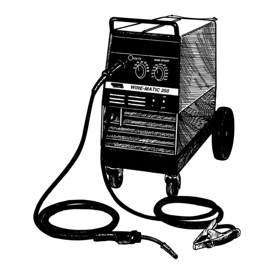
WIRE-MATIC 250
10003,
10004.
And,
SERVICE MANUAL
Sales and Service through Subsidiaries and Distributors Worldwide
9799,
9800,
18
16
14
Premier Manufacturer of Industrial Motors
SVM 117-A
December 1995
20
22
300
24
250
350
26
200
400
150
450
28
100
500
50
550
600
1
ON
0
OFF
Advertisement
Chapters
Table of Contents
Troubleshooting

Related Manuals for Lincoln Electric WIRE-MATIC SVM 117-A


Summary of Contents for Lincoln Electric WIRE-MATIC SVM 117-A
- Page 1 WIRE-MATIC 250 For use with machines having Code Numbers: Safety Depends on You Lincoln arc welding and cutting equipment is designed and built with safety in mind. However, your overall safety can be increased by proper installation ... and thoughtful operation on your part.
-
Page 2: Safety
Miami, Florida 33135 or CSA Standard W117.2-1974. A Free copy of “Arc Welding Safety” booklet E205 is available from the Lincoln Electric Company, 22801 St. Clair Avenue, Cleveland, Ohio 44117-1199. BE SURE THAT ALL INSTALLATION, OPERATION, MAINTENANCE AND REPAIR PROCEDURES ARE PER- FORMED ONLY BY QUALIFIED INDIVIDUALS. - Page 3 WELDING SPARKS can cause fire or explosion. 4.a. Remove fire hazards from the welding area. If this is not possible, cover them to prevent the welding sparks from starting a fire. Remember that welding sparks and hot materials from welding can easily go through small cracks and openings to adjacent areas.
- Page 4 FOR ENGINE powered equipment. 7.a. Turn the engine off before troubleshooting and maintenance work unless the maintenance work requires it to be running. ____________________________________________________ 7.b. Operate engines in open, well-ventilated areas or vent the engine exhaust fumes outdoors. ____________________________________________________ 7.c. Do not add the fuel near an open flame welding arc or when the engine is run- ning.
- Page 5 PRÉCAUTIONS DE SÛRETÉ Pour votre propre protection lire et observer toutes les instructions et les précautions de sûreté specifiques qui parraissent dans ce manuel aussi bien que les précautions de sûreté générales suiv- antes: Sûreté Pour Soudage A L’Arc 1. Protegez-vous contre la secousse électrique: a.
- Page 6 NOTES WIRE-MATIC 250...
-
Page 7: Table Of Contents
Safety ............i - v Installation . - Page 8 TABLE OF CONTENTS (continued) Theory of Operation ........Section E Power Supply Operation Thermal Protection .
-
Page 9: Installation
INSTALLATION TABLE OF CONTENTS - INSTALLATION SECTION - INSTALLATION SECTION ... Section A Technical Specifications ...A-1 Safety Precautions ...A-2 Select Proper Location...A-2 Stacking...A-2 Tilting ...A-2 Input Connections ...A-2 Fuse and Wire Sizes ...A-3 Input Power Connections and Ground Connections...A-3 Connect Shielding Gas...A-4 Reconnect Procedure...A-5 Connect Output Components...A-7 Install the Work Clamp ...A-7... -
Page 10: Technical Specifications
TECHNICAL SPECIFICATIONS - Wire-Matic-250 INPUT - SINGLE PHASE/ 60 HERTZ ONLY Standard Voltage 208/230/1/60 230/460/575 Duty Cycle 100% Current Range 30A - 250A RECOMMENDED INPUT WIRE & FUSE SIZE Input Voltage/ Fuse (Superlag) Frequency or Breaker Size 208/60 230/60 460/60 575/60 HEIGHT 28.2”... -
Page 11: Safety Precautions
2. Models that have multiple input voltages specified on the nameplate (e.g., 208/230) are shipped con- nected for the highest voltage. If the welder is to be operated at a lower voltage, it must be recon- nected according to the instructions on the inside of the removable panel (Reconnect Access Door) near the top left side of the Case Back Assembly. -
Page 12: Fuse And Wire Sizes
Figure A.2. A green wire in the input cord connects this ter- minal to the frame of the welder. This ensures proper grounding of the welder frame when the welder plug is inserted into the receptacle. -
Page 13: Connect Shielding Gas
1. Set the gas cylinder on the rear platform of the WIRE-MATIC 250. 2. Hook the chain in place to secure cylinder to rear of welder. 3. Remove the cylinder cap. 4. Inspect the cylinder valves for damaged threads, dirt, dust, oil or grease. -
Page 14: Reconnect Procedure
7. Attach the flow regulator to the cylinder valve and tighten the union nut(s) securely with a wrench. a. NOTE: If connecting the flow regulator to 100% CO cylinder, insert the regulator adapter provided with the optional K-586-1 Kit between the regulator and cylinder valve. If adapter is equipped with a plastic washer, be sure it is seated properly to connect to the CO cylinder. - Page 15 ALL MACHINES ARE SHIPPED FROM THE FACTORY CONNECTED FOR THE HIGHER OF THE TWO INPUT VOLTAGES LISTED ON THE NAMEPLATE. TO CHANGE VOLTAGE CONNECTION PROCEED AS FOLLOWS: 1. REMOVE THE OUTER STEEL HEX NUT FROM THE TERMINAL WHERE THE TRANSFORMER INPUT LEAD IS CONNECTED.
-
Page 16: Connect Output Components
Turn the welder Power Switch OFF before chang- ing output connection. ____________________________________ The welder is shipped from the factory connected for electrode positive (+) polarity. This is the normal polar- ity for GMA welding. If negative (-) polarity is required, interchange the con- nection of the two cables located in the wire drive com- partment near the front panel. -
Page 17: Wire Size Conversion Parts
(0.6-1.2mm) solid or cored electrode sizes. For vari- ous drive roll kits refer to Acessories Section . GUN AND CABLE INSTALLATION WARNING Turn the welder Power Switch OFF before chang- ing output connection. ____________________________________ 1. Lay the cable out straight. - Page 18 NOTES WIRE-MATIC 250...
-
Page 19: Operation
Procedure for Changing Drive Roll ...B-5 Loading the Wire Reel...B-5 Feeding Electrode ...B-6 Proper Wire Feeding ...B-6 Setting Idle Roll Pressure...B-7 Operating Steps ...B-7 Starting the Welder...B-7 Changing Run-In Mode ...B-7 Enter Fast Run-In Mode ...B-7 Enter Slow Run-In Mode...B-7 Making a Weld...B-8 WIRE-MATIC 250... -
Page 20: Safety Instructions
Read and understand this entire section before operat- ing your WIRE-MATIC 250. SAFETY INSTRUCTIONS WARNING ELECTRIC SHOCK can kill. • Do not touch electrically live parts such as output terminals or internal wiring. • Insulate yourself from the work and ground. •... -
Page 21: Recommended Processes And Equipment
RECOMMENDED PROCESSES AND EQUIPMENT The WIRE-MATIC 250 is recommended for GMA weld- ing processes using 10 to 30 lb. (4.5 to 13.6 kg) 2" (51mm) I.D. spools or Readi-Reel coils (with optional adapter) of: .025" through .045" (0.6-1.2mm) solid steel. .035"... -
Page 22: Machine Capability
WIRE FEEDER FEATURES: Drop-in Wire Loading - The innovative spindle snaps into the Readi-Reel adapter (optional) or most any 2" (51mm) I.D. wire spool. The wire spindle drops into the top-loading WIRE-MATIC Accommodating standard 12" (305mm) and 8" (203mm) diameter coils, the unique spindle and sup- port design automatically provides appropriate de-reel- ing drag to prevent wire reel overrun and loop-offs without manual brake adjustment. -
Page 23: Controls And Settings
CONTROLS AND SETTINGS All operator controls are located on the Front Panel/Nameplate of the machine. See Figure B.1 for the location of each control. LINCOLN ELECTRIC Figure B.1 - Operator Controls. 1. POWER SWITCH: Toggle switch to turn input power ON and OFF. Place the lever in the ON position to turn the WIRE-MATIC 250 ON. -
Page 24: Using The Wire Drive Roll
(0.8-0.9mm) solid steel electrode, and the other for .045" (1.2mm) solid steel electrode. The welder is shipped with the drive roll installed in the .030-.035" (0.8-0.9mm) position as indi- cated by the stenciling on the exposed side of the drive roll. -
Page 25: Feeding Electrode
NOTE: The retaining spring side of the adapter should be facing the center (inner) panel of the WIRE-MATIC 250. 10. Remove Readi-Reel from Adapter by depressing the retaining spring tab with thumb while pulling the Readi-Reel cage from the molded adapter with both hands. -
Page 26: Operating Steps
LED pilot light. 2. Select the correct voltage and wire speed for the welding process required. 3. Operate the gun trigger for welder output and to energize the wire feeder motor. OPERATION NOTE: When the POWER SWITCH is ON, the fan... -
Page 27: Making A Weld
NOTE. When the gun trigger is first closed before turn- ing on the welder, there is no output power or wire feed until the trigger is opened and re-closed, regardless of the WIRE SPEED CONTROL POTENTIOMETER KNOB setting. - Page 28 NOTES WIRE-MATIC 250...
-
Page 29: Accessories
ACCESSORIES TABLE OF CONTENTS - ACCESSORIES SECTION - ACCESSORIES SECTION ... Section C Replacement Magnum 250L Gun and Cable Assembly ...C-1 K607-1 Spool Gun Adapter Kit...C-1 Installing the K607-1 Spool Adapter Kit ...C-1 Spool Gun Module Board Installation ...C-2 Spool Gun Connection Box Installation ...C-3 Spool Gun Preparation...C-4 Spool Gun Connection ...C-4 Making a Weld with the Spool Gun Adapter (K607-1) -
Page 30: Replacement Magnum 250L Gun And Cable Assembly
OPTIONS/ACCESSORIES REPLACEMENT MAGNUM 250L GUN AND CABLE ASSEMBLY The following GMAW gun and cable assemblies are available for use with the WIRE-MATIC 250. Each is rated 200 amps 60% duty cycle or 250 amps 35% duty cycle. The gun and cable assemblies are equipped with the integrated connector, twist-lock trigger con- nector, and includes a liner, diffuser, and contact tips for the wire sizes specified:... -
Page 31: Spool Gun Module Board Installation
SPOOL GUN MODULE BOARD INSTALLATION NOTE: The K607-1 Spool Gun Adapter Kit is designed for use with WIRE-MATIC 250 model codes above 9900. Model Codes below 9900 may be used with addition of holes to the case as described in the instal- lation instructions below. -
Page 32: Spool Gun Connection Box Installation
CAUTION Collect metal filings with a rag to protect against possible metal contamination of the control board or other internal electrical components. ____________________________________ 12. Fasten the panel receptacle to the case with the three #6-32 x 3/8" self tapping screws provided. a. -
Page 33: Spool Gun Preparation
4. Pull the rubber boot over the plug to insulate the connection. SPOOL GUN CONNECTION The spool gun module is intended for use with Lincoln Electric Magnum Spool Guns only. Use with other units may cause damage to the equip- ment. For Spool Gun operation, refer to the instruction manual provided with the Magnum Spool Gun. -
Page 34: Making A Weld With The Spool Gun Adapter (K607-1) Installed
MAKING A WELD WITH THE SPOOL GUN ADAPTER (K607-1) INSTALLED The toggle switch on the front of the spool gun adapter box permits quick transfer when you want to switch between using the WIRE-MATIC 250 Feeder Gun and the connected Spool Gun when the electrodes are at the same polarity. -
Page 35: Timer Kit (K585-1
TIMER KIT (K585-1) The Timer Kit provides selectable 4-step trigger inter- lock, spot and stitch functions, and manual adjustment of burnback time. This kit installs easily using only a screwdriver. It replaces the blank upper panel on Case Front. It offers the following mode selections: •... -
Page 36: Making Spot And Stitch Welds With Timer Kit Installed
MAKING SPOT AND STITCH WELDS WITH TIMER KIT INSTALLED TO MAKE SPOT PLUG WELDS: The SPOT WELD MODE is used to make spot plug welds when continuous welds are not needed or to hold thin sheet metal together prior to stitch welding or continuous welding. -
Page 37: Maintenance
MAINTENANCE TABLE OF CONTENTS - MAINTENANCE SECTION - MAINTENANCE SECTION ... Section D Safety Precautions ...D-1 Routine and Periodic Maintenance ...D-1 Component Locations ...D-2 Drive Rolls and Guide Tubes ...D-3 Drop-In Reel Spindle and Clips ...D-3 Cable Cleaning...D-3 Gun Tubes and Nozzles...D-3 Contact Tip and Gas Nozzle Installation...D-3 Liner Removal and Replacement...D-4 Liner Removal, Installation, and Trimming Instructions... -
Page 38: Safety Precautions
SAFETY PRECAUTIONS WARNING • Have a qualified electrician do the maintenance and troubleshooting work. • Disconnect the input power off using the dis- connect switch at the main input supply before working inside machine. • Unplug the power cable if it is connected to a receptacle. - Page 39 MAINTENANCE Figure D.1 - Component Locations. WIRE-MATIC 250...
-
Page 40: Drive Rolls And Guide Tubes
DRIVE ROLLS AND GUIDE TUBES After every coil of wire, inspect the wire drive mecha- nism. Clean it as necessary by blowing with low pres- sure compressed air. Do not use solvents for cleaning the idle roll because it may wash the lubricant out of the bearing. -
Page 41: Liner Removal And Replacement
LINER REMOVAL AND REPLACEMENT NOTE: When you change wire size, a replacement gas diffuser is required. Use the table below to select the proper diffuser so the liner is held securely in place. Electrode Diameter Replacement Liner Part Number .025-.030" Steel (0.6-0.8mm) .035-.045"... -
Page 42: Gun Handle Disassembly
12 Remove any burrs from the end of the liner. 13. Screw the gas diffuser onto the end of the gun tube and tighten. NOTE: Be sure the gas diffuser is correct for the liner being used. (See table and diffuser stencil.) 14. -
Page 43: Accessories And Expendable Replacement Parts For Magnum 250L Gun And Cable Assemblies
ACCESSORIES AND EXPENDABLE REPLACEMENT PARTS FOR MAGNUM 250L GUN AND CABLE ASSEMBLIES DESCRIPTION Cable Liner For 15' (4.5m) or Shorter Cable Contact Tips Standard Duty Heavy Duty Tapered Gas Diffuser Assembly Gas Nozzles Adjustable Slip-On (Requires Nozzle Insulator Assembly.) Nozzle Insulator Assembly Gasless Nozzle (for Innershield®) Gun Tube Assembly Standard (60 Degrees) - Page 44 NOTES WIRE-MATIC 250...
-
Page 45: Theory Of Operation
THEORY OF OPERATION TABLE OF CONTENTS - THEORY OF OPERATION SECTION - THEORY OF OPERATION SECTION ... Section E Power Supply Operation ...E-1 Input Line Voltage and Main Transformer ...E-1 Output Rectification and Feedback Control ...E-2 Constant Voltage Output ...E-3 Wire Drive Motor and Feedback ...E-4 Thermal Protection ...E-5 SCR Operation ...E-6... - Page 46 THEORY OF OPERATION INPUT LINE VOLTAGE AND MAIN TRANSFORMER VOLTAGE MAIN LINE TRANSFORMER SWITCH RECONNECT MOTORS Figure E.2 - Input Line Voltage and Main Transformer. INPUT LINE VOLTAGE AND MAIN TRANSFORMER The desired single phase input power is connected to the WIRE-MATIC 250 through a line switch located on the front panel.
- Page 47 THEORY OF OPERATION OUTPUT RECTIFICATION AND FEEDBACK VOLTAGE MAIN LINE TRANSFORMER SWITCH RECONNECT MOTORS Figure E.3 - Output Rectification and Feedback. OUTPUT RECTIFICATION AND FEEDBACK CONTROL The AC output from the main transformer secondary weld winding is rectified and controlled through the SCR rectifier assembly.
- Page 48 THEORY OF OPERATION CONSTANT VOLTAGE OUTPUT VOLTAGE MAIN LINE TRANSFORMER SWITCH RECONNECT MOTORS CONSTANT VOLTAGE OUTPUT The controlled DC output from the SCR rectifier assembly is filtered by the capacitor bank resulting is a constant voltage DC output. Since the output choke is in series with the positive leg of the rectifier and also in series with the gun and welding load, a filtered con- stant voltage output is applied to the output terminals...
-
Page 49: Wire Drive Motor And Feedback
THEORY OF OPERATION WIRE DRIVE MOTOR AND FEEDBACK VOLTAGE MAIN LINE TRANSFORMER SWITCH RECONNECT MOTORS Figure E.5 - Wire Drive Motor and Feedback. WIRE DRIVE MOTOR AND FEEDBACK The wire drive motor is controlled by the control board. A motor speed feedback signal is generated at the motor tach and sent to the control board. -
Page 50: Thermal Protection
THEORY OF OPERATION THERMAL PROTECTION THERMAL PROTECTION A thermostat protects the machine from excessive operating temperatures. Excessive operating temper- atures may be caused by a lack of cooling air or oper- ating the machine beyond the duty cycle and output rating. -
Page 51: Scr Operation
THEORY OF OPERATION A silicon controlled rectifier (SCR) is a three terminal device used to control rather large currents to a load. An SCR acts very much like a switch. When a gate sig- nal is applied to the SCR it is turned ON and there is current flow from anode to cathode. - Page 52 NOTES WIRE-MATIC 250...
-
Page 53: Pc Board Troubleshooting Procedures
TROUBLESHOOTING & REPAIR - TROUBLESHOOTING & REPAIR SECTION - TROUBLESHOOTING & REPAIR SECTION ... Section F How to use Troubleshooting Guide ...F-1 PC Board Troubleshooting Procedures...F-2 Troubleshooting Guide ...F-3 Test Procedures Main Transformer Test...F-10 Static Output Rectifier Bridge Test ...F-13 Active SCR Rectifier Assembly Test ...F-16 Wire Drive Motor and Tachometer Feedback Test ...F-19 Oscilloscope Waveforms ...F-22... -
Page 54: Troubleshooting And Repair
TROUBLESHOOTING & REPAIR HOW TO USE TROUBLESHOOTING GUIDE Service and Repair should only be performed by Lincoln Electric Factory Trained Personnel. Unauthorized repairs performed on this equipment may result in danger to the technician and machine operator and will invalidate your factory warranty. For your safety and to avoid Electrical Shock, please observe all safety notes and precautions detailed throughout this manual. -
Page 55: Pc Board Troubleshooting Procedures
TROUBLESHOOTING & REPAIR PC BOARD TROUBLESHOOTING PROCEDURES WARNING ELECTRIC SHOCK can kill. Have an electrician install and service this equipment. Turn the input power OFF at the fuse box before work- ing on equipment. Do not touch electrically hot parts. _______________________________ CAUTION: Sometimes machine failures... -
Page 56: Troubleshooting Guide
If for any reason you do not understand the test procedures or are unable to perform the tests/repairs safely, con- tact the Lincoln Electric Service Department for technical troubleshooting assistance before you proceed call 216- 383-2531 or 1-800-833-9353... - Page 57 200 amps at 28 volts. If for any reason you do not understand the test procedures or are unable to perform the tests/repairs safely, con- tact the Lincoln Electric Service Department for technical troubleshooting assistance before you proceed call 216- 383-2531 or 1-800-833-9353...
- Page 58 NOT activated. If for any reason you do not understand the test procedures or are unable to perform the tests/repairs safely, con- tact the Lincoln Electric Service Department for technical troubleshooting assistance before you proceed call 216- 383-2531 or 1-800-833-9353...
- Page 59 If for any reason you do not understand the test procedures or are unable to perform the tests/repairs safely, con- tact the Lincoln Electric Service Department for technical troubleshooting assistance before you proceed call 216- 383-2531 or 1-800-833-9353...
- Page 60 If for any reason you do not understand the test procedures or are unable to perform the tests/repairs safely, con- tact the Lincoln Electric Service Department for technical troubleshooting assistance before you proceed call 216- 383-2531 or 1-800-833-9353...
- Page 61 If for any reason you do not understand the test procedures or are unable to perform the tests/repairs safely, con- tact the Lincoln Electric Service Department for technical troubleshooting assistance before you proceed call 216- 383-2531 or 1-800-833-9353 POSSIBLE AREAS OF...
- Page 62 The arc striking is poor. If for any reason you do not understand the test procedures or are unable to perform the tests/repairs safely, con- tact the Lincoln Electric Service Department for technical troubleshooting assistance before you proceed call 216- 383-2531 or 1-800-833-9353...
-
Page 63: Main Transformer Test
TROUBLESHOOTING & REPAIR MAIN TRANSFORMER TEST Service and repair should be performed only by Lincoln Electric factory trained per- sonnel. Unauthorized repairs performed on this equipment could result in danger to the technician or the machine operator and will invalidate your factory warranty. For your safety and to avoid electrical shock, please observe all safety notes and pre- cautions detailed throughout this manual. -
Page 64: Test Procedures
F-11 TROUBLESHOOTING & REPAIR MAIN TRANSFORMER TEST (CONTINUED) TEST PROCEDURE WARNING The ON/OFF POWER SWITCH will be "hot" during these tests. __________________________ NOTE: Secondary voltages will vary proportionably with the primary input voltage. 1. Disconnect the main input power supply to the machine. 2. - Page 65 F-12 TROUBLESHOOTING & REPAIR MAIN TRANSFORMER TEST (CONTINUED) 4. Locate the following leads on Plug G2332: LEAD #202 #203 #204 A 5. Connect main input power to the machine. 6. Turn the Wire-Matic 250 ON/OFF POWER SWITCH to ON. 7. Make the following voltage tests at Plug J3.
-
Page 66: Static Scr Rectifier Assembly Test
TROUBLESHOOTING & REPAIR STATIC SCR RECTIFIER ASSEMBLY TEST Service and repair should be performed only by Lincoln Electric factory trained per- sonnel. Unauthorized repairs performed on this equipment could result in danger to the technician or the machine operator and will invalidate your factory warranty. For your safety and to avoid electrical shock, please observe all safety notes and pre- cautions detailed throughout this manual. - Page 67 F-14 TROUBLESHOOTING & REPAIR STATIC SCR RECTIFIER ASSEMBLY TEST (CONTINUED) TEST PROCEDURE 1. Disconnect main AC input power to the machine. 2. Disconnect Plugs J3 and J6 from the G2332 Control Board. electrically isolates the SCR bridge assembly. See Figure F.2. WM-250 CONTROL G2332 FIGURE F.2 - Remove Plugs J3 and J6...
- Page 68 F-15 TROUBLESHOOTING & REPAIR STATIC SCR RECTIFIER ASSEMBLY TEST (CONTINUED) NOTE: DO NOT DISASSEMBLE THE SCR RECTIFIER HEAT SINK ASSEM- BLY. 6. Test for high or infinite resistance from the anode to the cathode of SCR 1. See Figure F.4. Use an analog ohmmeter (Multimeter).
-
Page 69: Active Scr Rectifier Assembly Test
ACTIVE SCR RECTIFIER ASSEMBLY TEST WARNING Service and repair should be performed only by Lincoln Electric factory trained per- sonnel. Unauthorized repairs performed on this equipment could result in danger to the technician or the machine operator and will invalidate your factory warranty. For your safety and to avoid electrical shock, please observe all safety notes and pre- cautions detailed throughout this manual. - Page 70 F-17 TROUBLESHOOTING & REPAIR ACTIVE SCR RECTIFIER ASSEMBLY TEST (CONTINUED) TEST PROCEDURE 1. Disconnect main AC input power to the machine. 2. Disconnect Molex Plugs J3 and J6 from the G2332 Control Board. See Figure F.5. WM-250 CONTROL G2332 FIGURE F.5 - Control Board Molex Plug Locations for G2332 PC Control Board.
- Page 71 F-18 TROUBLESHOOTING & REPAIR ACTIVE SCR RECTIFIER ASSEMBLY TEST (CONTINUED) 7. Connect the Tester to the SCR 1 as shown in Figure F.7. a. Connect Tester lead (A) to the anode. b. Connect Tester lead (C) to the cathode. c. Connect Tester lead (G) to the gate.
-
Page 72: Wire Drive Motor And Tachometer Feedback Test
TROUBLESHOOTING & REPAIR WIRE DRIVE MOTOR AND TACHOMETER FEEDBACK TEST Service and repair should be performed only by Lincoln Electric factory trained per- sonnel. Unauthorized repairs performed on this equipment could result in danger to the technician or the machine operator and will invalidate your factory warranty. For your safety and to avoid electrical shock, please observe all safety notes and pre- cautions detailed throughout this manual. - Page 73 F-20 TROUBLESHOOTING & REPAIR WIRE DRIVE MOTOR AND TACHOMETER FEEDBACK TEST (CONTINUED) TEST PROCEDURE NOTE: POLARITY OBSERVED FOR THESE TESTS. Test for Correct Wire Drive Motor Armature Voltage 1. Disconnect main input power to the machine. 2. Remove the Case Top and Side Panels using a 5/16"...
- Page 74 F-21 TROUBLESHOOTING & REPAIR WIRE DRIVE MOTOR AND TACHOMETER FEEDBACK TEST (CONTINUED) 4. Test for 2 - 25 VDC between lead #539 (positive) (8J5) and lead #541 (9J5) (negative) to determine if the correct armature voltage is being supplied. See Figure F.8. a.
-
Page 75: Normal Open Circuit Voltage Waveform
F-22 TROUBLESHOOTING & REPAIR NORMAL OPEN CIRCUIT VOLTAGE WAVEFORM This is a typical DC output voltage wave- form generated from a properly operating machine. Note that each vertical division represents 20 volts and that each horizontal division represents 2 milliseconds in time. Note: Scope probes connected at machine output terminals: (+) probe to electrode, (-) probe to work. -
Page 76: Typical Output Voltage Waveform - Machine Loaded
F-23 TROUBLESHOOTING & REPAIR TYPICAL OUTPUT VOLTAGE WAVEFORM - MACHINE LOADED MACHINE LOADED TO 250 AMPS AT 26 VDC This is a typical DC output voltage wave- form generated from a properly operating machine. Note that each vertical division represents 20 volts and that each horizontal division represents 5 milliseconds in time. -
Page 77: Abnormal Output Voltage Waveform - Machine Loaded One Output Scr Not Functioning
F-24 TROUBLESHOOTING & REPAIR ABNORMAL OUTPUT VOLTAGE WAVEFORM - MACHINE LOADED ONE OUTPUT SCR NOT FUNCTIONING MACHINE LOADED TO 220 AMPS AT 22 VDC This is NOT a typical DC output voltage waveform. One output SCR is not function- ing. Note the increased ripple content. One SCR gate was disconnected to simulate an open or non-functioning output SCR. -
Page 78: Abnormal Open Circuit Voltage Output Capacitor Bank Not Functioning
F-25 TROUBLESHOOTING & REPAIR ABNORMAL OPEN CIRCUIT VOLTAGE OUTPUT CAPACITOR BANK NOT FUNCTIONING This is NOT the typical DC output voltage waveform. The output capacitors are not functioning. Note the lack of “filtering” in the output waveform. The output capacitor bank was disconnected. -
Page 79: Typical Scr Gate Voltage Waveform
F-26 TROUBLESHOOTING & REPAIR TYPICAL SCR GATE VOLTAGE WAVEFORM This is a typical SCR gate pulse voltage waveform. The machine was in an open cir- cuit condition (no load) and operating prop- erly. Note that each vertical division repre- sents 2 volts and each horizontal division represents 5 milliseconds in time. -
Page 80: Control Pc Board Removal And Replacement
TROUBLESHOOTING & REPAIR CONTROL PC BOARD REMOVAL AND REPLACEMENT Service and repair should be performed only by Lincoln Electric factory trained per- sonnel. Unauthorized repairs performed on this equipment could result in danger to the technician or the machine operator and will invalidate your factory warranty. For your safety and to avoid electrical shock, please observe all safety notes and pre- cautions detailed throughout this manual. - Page 81 F-28 TROUBLESHOOTING & REPAIR CONTROL PC BOARD REMOVAL AND REPLACEMENT (CONTINUED) REMOVAL AND REPLACE- MENT PROCEDURE 1. Disconnect main input power the machine. 2. Remove the Case Top and Side Panels using 5/16" nut driver. 3. Disconnect all wiring harness plugs and Molex Plugs connected to the Control Board.
-
Page 82: Wire Drive Assembly Removal And Replacement
TROUBLESHOOTING & REPAIR WIRE DRIVE ASSEMBLY REMOVAL AND REPLACEMENT Service and repair should be performed only by Lincoln Electric factory trained per- sonnel. Unauthorized repairs performed on this equipment could result in danger to the technician or the machine operator and will invalidate your factory warranty. For your safety and to avoid electrical shock, please observe all safety notes and pre- cautions detailed throughout this manual. - Page 83 F-30 TROUBLESHOOTING & REPAIR WIRE DRIVE ASSEMBLY REMOVAL AND REPLACEMENT (CONTINUED) PROCEDURE 1. Disconnect main input power to the machine. 2. Remove the Case Top and Side Panels. 3. Remove the large mounting screw with a large slot head screwdriver located in front of the drive roll.
-
Page 84: Scr Output Rectifier Removal And Replacement
TROUBLESHOOTING & REPAIR SCR OUTPUT RECTIFIER REMOVAL & REPLACEMENT Service and repair should be performed only by Lincoln Electric factory trained per- sonnel. Unauthorized repairs performed on this equipment could result in danger to the technician or the machine operator and will invalidate your factory warranty. For your safety and to avoid electrical shock, please observe all safety notes and pre- cautions detailed throughout this manual. - Page 85 F-32 TROUBLESHOOTING & REPAIR SCR OUTPUT RECTIFIER REMOVAL & REPLACEMENT (CONTINUED) PROCEDURE 1. Disconnect Transformer Lead X1 from the heat sink on the left side of the machine (facing the front) using a 1/2" socket wrench. See Figure F.12. a. Thin lead is always on the out- board side of the connection.
-
Page 86: Capacitor Bank Removal And Replacement
TROUBLESHOOTING & REPAIR CAPACITOR BANK REMOVAL AND REPLACEMENT Service and repair should be performed only by Lincoln Electric factory trained per- sonnel. Unauthorized repairs performed on this equipment could result in danger to the technician or the machine operator and will invalidate your factory warranty. For your safety and to avoid electrical shock, please observe all safety notes and pre- cautions detailed throughout this manual. - Page 87 F-34 TROUBLESHOOTING & REPAIR CAPACITOR BANK REMOVAL AND REPLACEMENT (CONTINUED) PROCEDURE See Figure F.15 for location of Capacitor Bank Removal and Replacement com- ponents. FIGURE F.15 - Location of Capacitor Bank Removal and Replacement Components. 1. Disconnect main input power to the machine.
-
Page 88: Main Transformer Removal And Replacement
TROUBLESHOOTING & REPAIR MAIN TRANSFORMER REMOVAL AND REPLACEMENT Service and repair should be performed only by Lincoln Electric factory trained per- sonnel. Unauthorized repairs performed on this equipment could result in danger to the technician or the machine operator and will invalidate your factory warranty. For your safety and to avoid electrical shock, please observe all safety notes and pre- cautions detailed throughout this manual. - Page 89 F-36 TROUBLESHOOTING & REPAIR MAIN TRANSFORMER REMOVAL AND REPLACEMENT (CONTINUED) PROCEDURE 1. Disconnect main input power to the machine. 2. Remove the Case Top and Side Panels. 3. Perform Removal Procedure. 4. Remove lead X1 from the left side SCR heat sink assembly using a 1/2"...
-
Page 90: Fan Motor And Fan Removal And Replacement
TROUBLESHOOTING & REPAIR FAN MOTOR AND FAN REMOVAL AND REPLACEMENT Service and repair should be performed only by Lincoln Electric factory trained per- sonnel. Unauthorized repairs performed on this equipment could result in danger to the technician or the machine operator and will invalidate your factory warranty. For your safety and to avoid electrical shock, please observe all safety notes and pre- cautions detailed throughout this manual. - Page 91 F-38 TROUBLESHOOTING & REPAIR FAN MOTOR AND FAN REMOVAL AND REPLACEMENT (CONTINUED) PROCEDURE See Figure F.16 for fan motor and fan removal components. FIGURE F.16 - Fan Motor and Fan Removal Components 1. Remove the Case Back screws. 2. Remove the gas solenoid using a 3/4"...
- Page 92 F-39 TROUBLESHOOTING & REPAIR FAN MOTOR AND FAN REMOVAL AND REPLACEMENT (CONTINUED) 7. Remove the fan motor. a. Loosen and remove the two screws from the motor mounting bracket using a slot head screw driver. b. When the motor is free from the mounting bracket, place it care- fully on the bottom of the machine.
-
Page 93: Retest After Repair
F-40 F-40 TROUBLESHOOTING & REPAIR RETEST AFTER REPAIR INPUT IDLE AMPS AND WATTS Input Volts/Hertz Maximum Idle Amps Maximum Idle Watts 230/60 OPEN CIRCUIT VOLTAGE 10 to 40 VDC 35-40 VDC Strike Voltage WIRE SPEED RANGE 50 - 600 IPM (1.27 - 15.2 m/minute) WIRE-MATIC 250... - Page 94 NOTES WIRE-MATIC 250...
-
Page 95: Electrical Diagrams
TABLE OF CONTENTS - ELECTRICAL DIAGRAMS SECTION - Electrical Diagram Section ....... . . Section G Wiring Diagram (230/460/575) Code 10004 . - Page 96 NOTES WIRE-MATIC 250...
-
Page 97: Wiring Diagram (230/460/575) Code 10004
Wiring Diagram (230/460/575) Code 10004 OPTIONAL TIMER BOARD WIRE SPEED ARC VOLTAGE POWER-ON INDICATOR TRIGGER WORK N.A. LINE SWITCH NOTE: This diagram is for reference only. It may not be accurate for all machines covered by this manual. The specific diagram for a particular code is pasted inside the machine on one of the enclosure panels. ELECTRICAL DIAGRAMS CONTROL BOARD (J7) -
Page 98: Wiring Diagram (230/460/575) Code 10003
Wiring Diagram (230/460/575) Code 10003 OPTIONAL TIMER BOARD WIRE SPEED ARC VOLTAGE POWER-ON INDICATOR TRIGGER WORK N.A. R.F. FILTER LINE SWITCH NOTE: This diagram is for reference only. It may not be accurate for all machines covered by this manual. The specific diagram for a particular code is pasted inside the machine on one of the enclosure panels. ELECTRICAL DIAGRAMS CONTROL BOARD (J7) -
Page 99: Wiring Diagram (208/230) Code 9800
Wiring Diagram (208/230) Code 9800 OPTIONAL TIMER BOARD WIRE SPEED ARC VOLTAGE 541B 539B POWER-ON (J13) INDICATOR 325B 324B OPTIONAL SPOOL OR PULL GUN RECEPTACLE TRIGGER WORK N.A. R.F. FILTER SHUNT LINE SWITCH NOTE: This diagram is for reference only. It may not be accurate for all machines covered by this manual. The specific diagram for a particular code is pasted inside the machine on one of the enclosure panels. ELECTRICAL DIAGRAMS CONTROL BOARD (J7) -
Page 100: Wiring Diagram (208/230) Code 9799
Wiring Diagram (208/230) Code 9799 OPTIONAL TIMER BOARD WIRE SPEED ARC VOLTAGE 541B 539B POWER-ON (J13) INDICATOR 325B 324B OPTIONAL SPOOL OR PULL GUN RECEPTACLE TRIGGER WORK N.A. R.F. FILTER LINE SWITCH NOTE: This diagram is for reference only. It may not be accurate for all machines covered by this manual. The specific diagram for a particular code is pasted inside the machine on one of the enclosure panels. ELECTRICAL DIAGRAMS CONTROL BOARD (J7) -
Page 101: Control Pc Board (G2332) Schematic
NOTE: Lincoln Electric assumes no responsibility for liablilities resulting from board level troubleshooting. PC Board repairs will invalidate your factory warranty. Individual Printed Circuit Board Components are not available from Lincoln Electric. This information is provided for reference only. Lincoln Electric discourages board level troubleshooting and repair since it may compromise the quality of the design and may result in danger to the Machine Operator or Technician. -
Page 102: Control Pc Board (G2332) Layout
NOTE: Lincoln Electric assumes no responsibility for liablilities resulting from board level troubleshooting. PC Board repairs will invalidate your factory warranty. Individual Printed Circuit Board Components are not available from Lincoln Electric. This information is provided for reference only. Lincoln Electric discourages board level troubleshooting and repair since it may compromise the quality of the design and may result in danger to the Machine Operator or Technician.