Table of Contents
Advertisement
RETURN TO MAIN INDEX
SVM128-A
March, 1999
TM
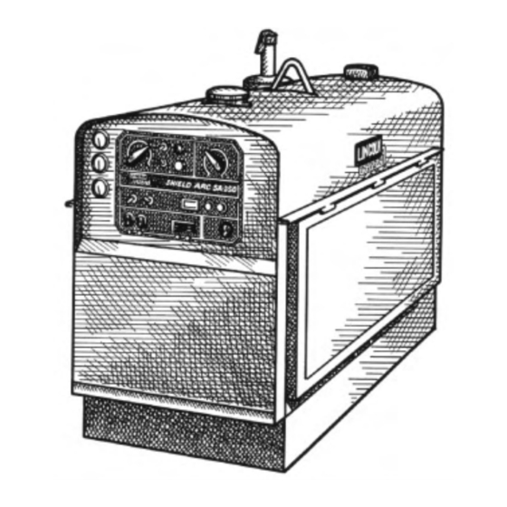
SHIELD-ARC SA-250
Diesel Engine Driven DC Arc Welding Power Source
For use with machine code numbers 10073 or 10073CV.
Safety Depends on You
Lincoln arc welding and cutting
equipment is designed and built
with safety in mind. However,
your overall safety can be in-
creased by proper installation . . .
and thoughtful operation on
your part. DO NOT INSTALL,
OPERATE OR REPAIR THIS
EQUIPMENT WITHOUT
READING THIS MANUAL AND
THE SAFETY PRECAUTIONS
CONTAINED THROUGHOUT.
And, most importantly, think
before you act and be careful.
SERVICE MANUAL
World's Leader in Welding and Cutting Products
Premier Manufacturer of Industrial Motors
• Sales and Service through Subsidiaries and Distributors Worldwide •
Cleveland, Ohio 44117-1199 U.S.A. TEL: 216.481.8100 FAX: 216.486.1751 WEB SITE: www.lincolnelectric.com
Advertisement
Chapters
Table of Contents
Troubleshooting

Related Manuals for Lincoln Electric SHIELD-ARC SVM128-A


Summary of Contents for Lincoln Electric SHIELD-ARC SVM128-A
- Page 1 RETURN TO MAIN INDEX SVM128-A March, 1999 SHIELD-ARC SA-250 Diesel Engine Driven DC Arc Welding Power Source For use with machine code numbers 10073 or 10073CV. Safety Depends on You Lincoln arc welding and cutting equipment is designed and built with safety in mind.
-
Page 2: Safety
Miami, Florida 33135 or CSA Standard W117.2-1974. A Free copy of “Arc Welding Safety” booklet E205 is available from the Lincoln Electric Company, 22801 St. Clair Avenue, Cleveland, Ohio 44117-1199. BE SURE THAT ALL INSTALLATION, OPERATION, MAINTENANCE AND REPAIR PROCEDURES ARE PERFORMED ONLY BY QUALIFIED INDIVIDUALS. -
Page 3: Electric Shock Can Kill
ELECTRIC SHOCK can kill. 3.a. The electrode and work (or ground) circuits are electrically “hot” when the welder is on. Do not touch these “hot” parts with your bare skin or wet clothing. Wear dry, hole-free gloves to insulate hands. - Page 4 WELDING SPARKS can cause fire or explosion. 6.a. Remove fire hazards from the welding area. If this is not possible, cover them to prevent the welding sparks from starting a fire. Remember that welding sparks and hot materials from welding can easily go through small cracks and openings to adjacent areas.
- Page 5 PRÉCAUTIONS DE SÛRETÉ Pour votre propre protection lire et observer toutes les instructions et les précautions de sûreté specifiques qui parraissent dans ce manuel aussi bien que les précautions de sûreté générales suiv- antes: Sûreté Pour Soudage A L’Arc 1. Protegez-vous contre la secousse électrique: a.
-
Page 6: Table Of Contents
MASTER TABLE OF CONTENTS FOR ALL SECTIONS Safety ...i-iv Installation...Section A Technical Specifications ...A-2 Safety Precautions ...A-3 Location and Ventilation ...A-3 Pre-operation Engine Service ...A-4 Electrical Output Connections...A-6 Operation...Section B Safety Instructions...B-2 General Description ...B-2 Recommended Applications...B-3 Operational Features and Controls...B-3 Design Features...B-3 Welding Capability ...B-4 Limitations ...B-4... - Page 7 Section A-1 - INSTALLATION SECTION - Installation Technical Specifications ...A-2 Safety Precautions ...A-3 Location and Ventilation ...A-3 Storing ...A-3 Stacking ...A-4 Tilting ...A-4 Lifting ...A-4 High Altitude Operation...A-4 Pre-operation Engine Service ...A-4 Oil ...A-4 Fuel...A-4 Battery Connections ...A-4 Cooling System...A-5 Muffler ...A-5 Exhaust Spark Arrester...A-5 Trailer ...A-5...
-
Page 8: Installation
38.2 HP @ 1725 RPM Duty Cycle 100% Duty Cycle 60% Duty Cycle 35% Duty Cycle OUTPUT - WELDER AND GENERATOR Welding Ranges Max. Open Circuit Voltage 40-325 Amps DC Height 43.1 in. 1096 mm Lincoln rating. Nema rating at 60% duty cycle is 250 amps @ 30 V. -
Page 9: Safety Precautions
Always operate the SA-250 with the doors closed. Leaving the doors open changes the designed air flow and may cause overheating. Always operate the welder with the case roof on and all machine compo- nents completely assembled. Whenever you use the SA-250, be sure that clean cooling air can flow through the machine’s diesel... -
Page 10: Pre-Operation Engine Service
Lift only with equipment of adequate lifting capacity. Be sure machine is stable when lifting. HIGH ALTITUDE OPERATION It may be necessary to derate welder output at higher altitudes. Some engine adjustment may be required. Contact a Perkins Service Representative. -
Page 11: Cooling System
(See your engine manual or antifreeze con- tainer for alternate antifreeze recommendations.) MUFFLER This welder is supplied with an adjustable rain cap for the muffler. Install the rain cap using the clamp provid- ed with the outlet facing away from the direction in which this unit will be transported. -
Page 12: Electrical Output Connections
Cable diameters are increased for long cable lengths to reduce voltage drops. Lincoln Electric offers a welding accessory kit with the properly specified welding cables. Accessories section of this manual for more information. -
Page 13: Machine Grounding
(If an older portable welder does not have a grounding stud, connect the ground wire to an unpainted frame screw. See Figure A.2. - Page 14 NOTES SA-250...
-
Page 15: Operation...............................................................................................................................section B Safety Instructions
Section B-1 - OPERATION SECTION - Operation...Section B Safety Instructions...B-2 General Description ...B-2 Recommended Applications...B-3 Welder ...B-3 Generator...B-3 Operational Features and Controls...B-3 Design Features...B-3 Welding Capability ...B-4 Limitations ...B-4 Controls and Settings...B-5 Welder/Generator Controls...B-5 Control of Welding Current ...B-6 Diesel Engine Controls: ...B-7 Engine Operation ...B-8... -
Page 16: Operation
OPERATING INSTRUCTIONS Read and understand this entire section before operat- ing your SA-250. SAFETY INSTRUCTIONS WARNING Do not attempt to use this equipment until you have thoroughly read all the operation and maintenance manuals supplied with your machine. They include important safety precautions;... -
Page 17: Recommended Applications
(SMAW) welding and for DC TIG welding. It also offers constant voltage output for DC semiautomatic wire feed welding. For more details on using the machine as a welder, see Welding Operation in the Operation section of this manual. GENERATOR The SA-250 is also capable of providing 3.0 kVA of... -
Page 18: Welding Capability
WELDING CAPABILITY The SA-250 is rated 250 amps, 40 volts constant cur- rent DC at 60% duty cycle based on a ten minute time period. Longer duty cycles at lower output currents are possible. The current is continuously variable from 40 to 325 amps DC. -
Page 19: Controls And Settings
CONTROLS AND SETTINGS The welder/generator controls are located on the Output Control Panel of the machine case front. Diesel engine idler control and start/stop controls are also on WELDER/GENERATOR CONTROLS See Figure B.1 for the location of the following fea- tures: 1. -
Page 20: Control Of Welding Current
CONTROL OF WELDING CURRENT CAUTION • DO NOT turn the CURRENT RANGE SELECTOR while welding because the current may arc between the contacts and damage the switch. • DO NOT attempt to set the CURRENT RANGE SELECTOR between the five points designated on the nameplate. -
Page 21: Diesel Engine Controls
FIGURE B.3 – DIESEL ENGINE CONTROLS 1. IDLER CONTROL TOGGLE SWITCH 2. IGNITION TOGGLE SWITCH 3. RESET BUTTON 4. START PUSHBUTTONS 5. ENGINE HOUR METER 6. OIL PRESSURE GAUGE 7. AMMETER 8. WATER TEMPERATURE GAUGE DIESEL ENGINE CONTROLS See Figure B.3 for the location of the following fea- tures: 1. -
Page 22: Engine Operation
ENGINE OPERATION WARNING DO NOT RUN THE ENGINE AT EXCESSIVE SPEEDS. The maximum allowable high idle speed for the SA-250 is 1800 RPM, no load. Do NOT increase the idle speed on the engine. Severe personal injury and damage to the machine can result if it is operated at speeds above the maximum rated speed. -
Page 23: Stopping The Engine
Thermostart feature. Follow the instructions on the nameplate and in the engine manual shipped with the welder. With a fully charged battery and the proper weight oil, the engine should start satisfactorily even when the air temperature is down to about 0 F (-18°C). -
Page 24: Welding Operation
B-10 WELDING OPERATION TO USE THE SA-250 FOR DC CONSTANT CURRENT STICK OR TIG WELDING: 1. Remove the flange nuts from the weld output ter- minals and place the work and electrode welding cables over the terminals. Replace and tighten the flange nuts securely. Be sure the connections are tight. - Page 25 B-11 TO USE THE SA-250 FOR DC WIRE FEED WELDING (CONSTANT VOLTAGE WITH WIRE FEED MODULE): 1. Connect the LN-25 or LN-7 Wire Feeder. Follow the installation instructions provided with the wire feeder. 2. Set the machine for CV operation. 3.
-
Page 26: Auxiliary Power
B-12 AUXILIARY POWER WARNING Be sure that any electrical equipment plugged into the generator AC power receptacles can withstand a ±10% voltage and a ±3% frequency variation. The AC auxiliary power, supplied as a standard, has a rating of 3.0 kVA of 115/230V AC power (60 hertz). One 115V duplex and one 230V duplex grounding type receptacle are provided. - Page 27 Options/Accessories ...C-2 TIG Welding Accessories...C-3 Semiautomatic FCAW and MIG Welding Accessories ...C-3 Connection of Lincoln Electric Wire Feeders...C-4 Connection of the LN-7 using K867 Universal Adapter...C-4 Connection of the LN-7 using K584 Input Cable Assembly ...C-5 Connection of the LN-25 using K867 Universal Adapter...C-6 Connection of the LN-25 “Across the Arc”...
-
Page 28: Accessories
WARNING PIPE THAWING can result in fire, explosion, damage to pipes, wiring, and the welder as well as other unsafe or hazardous conditions. Do not use a welder to thaw pipes before reviewing Lincoln Bulletin E695.1 (dated October 1987 or later). -
Page 29: Tig Welding Accessories
TIG WELDING ACCESSORIES TIG Module (K930-1) - The TIG Module is an acces- sory that provides high frequency and shielding gas control for DC GTAW (TIG) welding applications. The K930-1 TIG Module is supplied without acces- sories. Arc Start switches, Amptrols, cables, torches and mounting brackets must be purchased separately. -
Page 30: Connection Of Lincoln Electric Wire Feeders
CONNECTION OF LINCOLN ELECTRIC WIRE FEEDERS CONNECTION OF THE LN-7 TO THE SA-250 WITH K623-1 WIRE FEED MODULE USING K867 UNIVERSAL ADAPTER (SEE FIGURE C.1.) 1. Shut the welder off. 2. Connect the electrode cable from the LN-7 to the “+”... - Page 31 6. Adjust wire feed speed at the LN-7. NOTE: For remote control, a K857 control is required. Connect it to the K864 adapter. CAUTION When the welder is in local control, the electrode is always “HOT.” FIGURE C.2 14 PIN...
- Page 32 1. Shut the welder off. 2. Connect the electrode cable from the LN-25 to the “+” terminal of the welder. Connect the work cable to the “CV-” terminal of the welder. NOTE: Welding cable must be sized for current and duty cycle of application.
- Page 33 1. Shut the welder off. 2. Connect the electrode cable from the LN-25 to the “+” terminal of the welder. Connect the work cable to the “CV–” terminal of the welder. NOTE: Welding cable must be sized for current and duty cycle of application.
-
Page 34: Connection Of The K488 Sg Control Module And K487 Magnum Spool Gun
2. Connect the electrode cable from the SG Control Module to the “+” terminal of the welder. Connect the work cable to the “CV–” terminal of the welder. NOTE: Welding cable must be sized for current and duty cycle of application. -
Page 35: Routine And Periodic Maintenance
Tightening the Fan Belt ...D-8 Engine Maintenance Schedule...D-9 Battery Maintenance ...D-10 Cleaning the Battery ...D-10 Checking Specific Gravity ...D-10 Checking Electrolyte Level ...D-10 Charging the Battery ...D-10 Welder/Generator Maintenance...D-11 Storage ...D-11 Cleaning...D-11 Nameplates...D-11 Brush Removal and Replacement...D-11 Commutator and Brushes...D-11 Bearings...D-11 Current Range Selector Contacts...D-11... -
Page 36: Safety Precautions
SAFETY PRECAUTIONS WARNING • Have qualified personnel do all maintenance and troubleshooting work. • Turn the engine off before working inside the machine. • Remove covers or guards only when necessary to perform maintenance and replace them when the maintenance requiring their removal is complete. •... -
Page 37: Change The Oil Filter
CHANGE THE OIL FILTER: Change the oil filter the first time between 25 and 50 hours of operation. Then, under normal operating conditions, change the oil filter after every 200 to 250 hours of operation. If the engine is operated under heavy load or in high ambient tem- peratures, change the oil filter more frequently. -
Page 38: Fuel Filter
FUEL FILTER: Inspect the fuel filter daily. Drain any accumulated water from the engine fuel filter/water separator daily. Change the fuel filter every 400 hours of operation. Dust and dirt in the fuel system can cause the injection pump and injection nozzle to wear quickly. -
Page 39: How To Eliminate Air From The Fuel System
HOW TO ELIMINATE AIR FROM THE FUEL SYSTEM There are two methods to eliminate air from the fuel system according to the type of pump fitted: See Figure D.3. The standard method is used where the fuel injection pump has vent screws 4 and 5. The self-vent method is used where the fuel injection pump has a self-vent feature. - Page 40 7. See Figure D.4. Loosen the union nut (1) at the fuelled starting aid (if one is fitted) and operate the lift pump until fuel, free from air, comes from the connection. Tighten the union nut at the starting aid. 8.
-
Page 41: Cooling System
COOLING SYSTEM: The Perkins diesel engine is water cooled. Check the coolant level at the radiator filler daily. Add a 50-50 mixture of water and antifreeze as needed. To drain and refill the system, do the fol- lowing: 1. Ensure that the machine is on level ground. WARNING To avoid personal injury, never remove the radiator pressure cap nor the reserve tank cap while the engine... -
Page 42: Tightening The Fan Belt
TIGHTENING THE FAN BELT: Fan belts tend to loosen after the first 50 hours of operation. If the fan belts are loose, the engine can overheat and the bat- tery can lose its charge. Check belt tightness by press- ing on the belt midway between the pulleys. The belt should deflect no more than 10 mm (0.375 in.). -
Page 43: Engine Maintenance Schedule
PERKINS ENGINE MAINTENANCE SCHEDULE FREQUENCY MAINTENANCE REQUIRED Daily or Before • Fill fuel tank. Starting Engine • Check oil level. • Check air cleaner for dirty, loose, or damaged parts. • Check air intake and cooling areas, clean as necessary. •... -
Page 44: Battery Maintenance
GROUND - Damage to the engine alternator and the printed circuit board can result from incorrect connection. • CONNECTING A BATTERY CHARGER - Remove the battery from the welder by disconnecting the negative cable first, then the positive cable and battery clamp. When reinstalling, connect the negative cable last. -
Page 45: Welder/Generator Maintenance
- in the direction of rota- tion only - until brushes seat property. Brushes must be seated 100%. COMMUTATOR AND BRUSHES: brushes are properly adjusted when the welder is shipped. They require no particular attention. CAUTION DO NOT SHIFT THE BRUSHES or adjust the rocker setting. -
Page 46: Idler Maintenance
3. Proper operation of the idler requires good ground- ing of the printed circuit board (through its mount- ing), reed switch and battery. 4. If desired, the welder can be used without auto- matic idling by setting the “Idler Control” switch to the “High Idle” position. -
Page 47: Major Component Locations
D-13 FIGURE D.5 - MAJOR COMPONENT LOCATIONS 1. RIGHT CASE SIDE (DOOR) 2. BASE (WITH BATTERY) 3. ALTERNATOR BRUSHES 4. ALTERNATOR 5. GENERATOR 6. GENERATOR BRUSHES 7. OUTPUT TERMINALS 8. FUEL TANK 9. CASE FRONT WITH CONTROL PANEL 10. LEFT CASE SIDE 11. - Page 48 D-14 D-14 NOTES SA-250...
- Page 49 Section E-1 -THEORY OF OPERATION SECTION- Theory of Operation ...Section E General Description ...E-2 Battery, Starter, Engine Alternator, and Protection Circuits ...E-2 Engine, Generator Armature and Frame, Alternator Stator and Rotor...E-3 Excitation (Flashing)...E-3 Auxiliary and Field Feedback Coils ...E-3 Interpole and Series Coils...E-4 Current Range Selector ...E-4 Fine Current Adjustment ...E-4 Engine Idler Circuit...E-4...
-
Page 50: Theory Of Operation
THEORY OF OPERATION FIGURE E.2 – BATTERY, STARTER, ENGINE ALTERNATOR, AND PROTECTION CIRCUITS PROTECTION RELAY IDLER BOARD PRESSURE TEMPERATURE SWITCH GAUGE FUEL INJECTION PUMP ENGINE IGNITION ENGINE SWITCH ALTERNATOR STARTER MOTOR BATTERY GENERAL DESCRIPTION The SA-250 is a heavy duty, engine driven DC arc welding power source capable of providing constant current output for stick welding or DC TIG welding. -
Page 51: Engine, Generator Armature And Frame, Alternator Stator And Rotor
THEORY OF OPERATION FIGURE E.3 – ENGINE GENERATOR ARMATURE AND FRAME, ALTERNATOR STATOR AND ROTOR PROTECTION RELAY IDLER BOARD PRESSURE TEMPERATURE SWITCH GAUGE FUEL INJECTION PUMP ENGINE IGNITION ENGINE SWITCH ALTERNATOR STARTER MOTOR BATTERY ENGINE, GENERATOR ARMATURE AND FRAME, ALTERNATOR STATOR AND ROTOR EXCITATION (FLASHING) When the engine is started and running, the residual... -
Page 52: Interpole And Series Coils
THEORY OF OPERATION INTERPOLE AND SERIES COILS The generator armature rotates within the magnetic field created by the field shunt windings. A DC voltage is induced in the armature and is transferred, through the armature commutator and brushes, to the series and interpole coils. -
Page 53: Dc Generator Machines
THEORY OF OPERATION FIGURE E.4 – DC GENERATOR MACHINES MECHANICAL COUPLING DC GENERATOR MACHINES The armature winding of a DC generator is located on the rotating member. Current is conducted from it by means of carbon brushes. The field winding is located in the stator, which is stationary, and is excited by direct current. - Page 54 NOTES SA-250...
- Page 55 Section F-1 TROUBLESHOOTING & REPAIR SECTION Troubleshooting & Repair Section ...Section F How to Use Troubleshooting Guide ...F-2 PC Board Troubleshooting Procedures ...F-3 Troubleshooting Guide ...F-4 - F-12 Test Procedures ...F-13 Alternator Rotor Test...F-13 Field Shunt Winding Test...F-17 Idler Solenoid Test ...F-20 Engine Throttle Adjustment Test...F-22 Flashing the Fields ...F-26 Oscilloscope Waveforms...F-28...
-
Page 56: Troubleshooting And Repair
TROUBLESHOOTING & REPAIR HOW TO USE TROUBLESHOOTING GUIDE Service and repair should be performed by only Lincoln Electric Factory Trained Personnel. Unauthorized repairs performed on this equipment may result in danger to the technician and machine operator and will invalidate your factory warranty. For your safety and to avoid Electrical Shock, please observe all safety notes and precautions detailed throughout this manual. -
Page 57: Pc Board Troubleshooting Procedures
• If the PC Board uses protective shorting jumpers, don’t remove them until installation is complete. • If you return a PC Board to The Lincoln Electric Company for credit, it must be in the static-shielding bag. This will prevent further damage and allow prop- er failure analysis. -
Page 58: Troubleshooting Guide
AC auxiliary output voltage. If for any reason you do not understand the test procedures or are unable to perform the test/repairs safely, con- tact the Lincoln Electric Service Department for electrical troubleshooting assistance before you proceed. Call 216-383-2531 or 1-800-833-9353. - Page 59 If for any reason you do not understand the test procedures or are unable to perform the test/repairs safely, con- tact the Lincoln Electric Service Department for electrical troubleshooting assistance before you proceed. Call 216- 383-2531 or 1-800-833-9353.
- Page 60 If for any reason you do not understand the test procedures or are unable to perform the test/repairs safely, con- tact the Lincoln Electric Service Department for electrical troubleshooting assistance before you proceed. Call 216-383-2531 or 1-800-833-9353. POSSIBLE AREAS OF...
- Page 61 Control rheostat is adjusted. If for any reason you do not understand the test procedures or are unable to perform the test/repairs safely, con- tact the Lincoln Electric Service Department for electrical troubleshooting assistance before you proceed. Call 216- 383-2531 or 1-800-833-9353.
- Page 62 If for any reason you do not understand the test procedures or are unable to perform the test/repairs safely, con- tact the Lincoln Electric Service Department for electrical troubleshooting assistance before you proceed. Call 216-383-2531 or 1-800-833-9353.
- Page 63 If for any reason you do not understand the test procedures or are unable to perform the test/repairs safely, con- tact the Lincoln Electric Service Department for electrical troubleshooting assistance before you proceed. Call 216-383-2531 or 1-800-833-9353. detailed in the beginning of this manual.
- Page 64 The engine will not shut down. If for any reason you do not understand the test procedures or are unable to perform the test/repairs safely, con- tact the Lincoln Electric Service Department for electrical troubleshooting assistance before you proceed. Call 216-383-2531 or 1-800-833-9353.
- Page 65 If for any reason you do not understand the test procedures or are unable to perform the test/repairs safely, con- tact the Lincoln Electric Service Department for electrical troubleshooting assistance before you proceed. Call 216-383-2531 or 1-800-833-9353.
- Page 66 If for any reason you do not understand the test procedures or are unable to perform the test/repairs safely, con- tact the Lincoln Electric Service Department for electrical troubleshooting assistance before you proceed. Call 216-383-2531 or 1-800-833-9353. detailed in the beginning of this manual.
-
Page 67: Alternator Rotor Test
TROUBLESHOOTING & REPAIR ALTERNATOR ROTOR TEST Service and repair should be performed by only Lincoln Electric factory trained personnel. Unauthorized repairs performed on this equipment may result in danger to the technician or machine operator and will invalidate your factory warranty. For your safety and to avoid electrical shock, please observe all safety notes and precautions detailed throughout this manual. -
Page 68: Slip Rings
F-14 TROUBLESHOOTING & REPAIR ALTERNATOR ROTOR TEST (continued) ALTERNATOR COVER SLIP RINGS BRUSHES TEST PROCEDURE 1. Turn engine off. 2. Unlatch, lift and secure the right and left side doors. Note that there are latches at both ends of the door. 3. - Page 69 F-15 TROUBLESHOOTING & REPAIR ALTERNATOR ROTOR TEST (continued) 8. Working from the left side of the machine, measure the resistance across the rotor slip rings. A. Set the ohmmeter on the low scale (X1). B. Place one meter probe on one of the rotor slip rings.
- Page 70 F-16 TROUBLESHOOTING & REPAIR ALTERNATOR ROTOR TEST (continued) 9. Measure the rotor resistance to ground. A. Set the ohmmeter on the high scale (X100,000). B. Place one probe on either of the rotor slip rings. Place the other probe on any good, unpainted ground.
-
Page 71: Field Shunt Winding Test
TROUBLESHOOTING & REPAIR FIELD SHUNT WINDING TEST Service and repair should be performed by only Lincoln Electric factory trained personnel. Unauthorized repairs performed on this equipment may result in danger to the technician or machine operator and will invalidate your factory warranty. For your safety and to avoid elec- trical shock, please observe all safety notes and precautions detailed throughout this manual. - Page 72 F-18 TROUBLESHOOTING & REPAIR FIELD SHUNT WINDING TEST (continued) TEST PROCEDURE 1. Turn engine off. 2. Unlatch, lift and secure the right side door. Note that there are latches at both ends of the door. 3. Locate plug P10. See Figure F.4. FIGURE F.4 –...
- Page 73 F-19 TROUBLESHOOTING & REPAIR FIELD SHUNT WINDING TEST (continued) FIGURE F.5 – SHUNT LEAD RESISTANCE CHECK PIN 5 6. Using the volt/ohmmeter set on the low scale (X1), measure the resistance between the blue and the brown leads. See Figure F.5. approximately 50 ohms.
-
Page 74: Idler Solenoid Test
F-20 TROUBLESHOOTING & REPAIR Service and repair should be performed by only Lincoln Electric factory trained personnel. Unauthorized repairs performed on this equipment may result in danger to the technician or machine operator and will invalidate your factory warranty. For your safety and to avoid elec- trical shock, please observe all safety notes and precautions detailed throughout this manual. - Page 75 F-21 TROUBLESHOOTING & REPAIR IDLER SOLENOID TEST (continued) FIGURE F.6 - SOLENOID LEAD CONNECTIONS SOLENOID LEADS 56 & 57 TEST PROCEDURE 1. Turn engine off. 2. Unlatch, lift and secure the left side door. Note that there are latches at both ends of the door.
-
Page 76: Engine Throttle Adjustment Test
TROUBLESHOOTING & REPAIR ENGINE THROTTLE ADJUSTMENT TEST Service and repair should be performed by only Lincoln Electric factory trained personnel. Unauthorized repairs performed on this equipment may result in danger to the technician or machine operator and will invalidate your factory warranty. For your safety and to avoid elec- trical shock, please observe all safety notes and precautions detailed throughout this manual. - Page 77 ENGINE THROTTLE ADJUSTMENT TEST (continued) FIGURE F.7 - STROBE MARK LOCATION TEST PROCEDURE Strobe Tach Method 1. Turn the engine welder OFF. 2. Unlatch, lift and secure the left side door. Note that there are latches at both ends of the door.
- Page 78 F-24 TROUBLESHOOTING & REPAIR ENGINE THROTTLE ADJUSTMENT TEST (continued) 6. If either of the readings is incorrect, adjust the throttle as follows: Adjust HIGH IDLE: Use the 8mm wrench to loosen the locking nut. See Figure F.8 for location of the adjusting screw and locking nut.
- Page 79 F-25 TROUBLESHOOTING & REPAIR ENGINE THROTTLE ADJUSTMENT TEST (continued) FIGURE F.8 - HIGH IDLE ADJUSTMENT FIGURE F.9 - LOW IDLE ADJUSTMENT ADJUSTING SCREW LOCKING THREADED SOLENOID LEVER ARM LOCKING NUT SA-250 F-25...
-
Page 80: Flashing The Fields
F-26 TROUBLESHOOTING & REPAIR Service and repair should be performed by only Lincoln Electric factory trained personnel. Unauthorized repairs performed on this equipment may result in danger to the technician or machine operator and will invalidate your factory warranty. For your safety and to avoid elec- trical shock, please observe all safety notes and precautions detailed throughout this manual. - Page 81 FIGURE F.10 - FLASHING THE FIELDS 12 VOLT BATTERY PROCEDURE 1. Turn engine welder OFF. 2. Unlatch, lift and secure the right and left side doors. Note that there are latches at both ends of the door. 3. Remove the cover from the exciter.
-
Page 82: Normal Open Circuit Voltage Waveform (115Vac Supply
F-28 TROUBLESHOOTING & REPAIR NORMAL OPEN CIRCUIT VOLTAGE WAVEFORM (115VAC SUPPLY) HIGH IDLE – NO LOAD – FINE CURRENT CONTROL RHEOSTAT AT MAXIMUM 16.6 ms 5 ms 50 volts This is the typical auxiliary output voltage generated from a properly operating machine. -
Page 83: Normal Open Circuit Dc Weld Voltage Waveform
F-29 TROUBLESHOOTING & REPAIR NORMAL OPEN CIRCUIT DC WELD VOLTAGE WAVEFORM HIGH IDLE – NO LOAD – FINE CURRENT CONTROL RHEOSTAT AND SELECTOR SWITCH AT MAXIMUM 5 ms 50 volts This is the typical DC output voltage generated from a properly operating machine. -
Page 84: Typical Dc Weld Output Voltage Waveform
F-30 TROUBLESHOOTING & REPAIR TYPICAL DC WELD OUTPUT VOLTAGE WAVEFORM MACHINE LOADED – SELECTOR SWITCH AT MAXIMUM POSITION MACHINE LOADED TO 250 AMPS AT 40 VDC 5 ms 20 volts This is the typical DC output voltage generated from a properly operating machine. -
Page 85: Alternator Rotor Removal And Replacement
TROUBLESHOOTING & REPAIR ALTERNATOR ROTOR REMOVAL Service and repair should be performed by only Lincoln Electric factory trained personnel. Unauthorized repairs performed on this equipment may result in danger to the technician or machine operator and will invalidate your factory warranty. For your safety and to avoid elec- trical shock, please observe all safety notes and precautions detailed throughout this manual. - Page 86 F-32 TROUBLESHOOTING & REPAIR ALTERNATOR ROTOR REMOVAL AND REPLACEMENT (continued) PROCEDURE 1. Turn the engine off. 2. Unlatch, lift and secure the left and right side doors. There are latches on both sides of the doors. FIGURE F.11 – FRONT PANEL REMOVAL REMOVE FASTENERS 3.
- Page 87 F-33 TROUBLESHOOTING & REPAIR ALTERNATOR ROTOR REMOVAL AND REPLACEMENT (continued) See Figure F.12 for steps 5 - 8. 5. With the 3/8" wrench, loosen the two screws on the left side of the alternator cover. 6. With the 3/8" wrench, remove the screw and lock washer from the top center of the alter- nator cover.
- Page 88 F-34 TROUBLESHOOTING & REPAIR ALTERNATOR ROTOR REMOVAL AND REPLACEMENT (continued) See Figure F.13 for steps 9 - 11. 9. With the 7/16" wrench, remove the two bolts, nuts and washers mounting the brush holder assembly to the stator frame. 10. Bend the flat washer away from the rotor locking nut.
- Page 89 F-35 ALTERNATOR ROTOR REMOVAL AND REPLACEMENT (continued) Replacement 12. Carefully mount the rotor onto the generator shaft. Install a new sleeve collar (part num- ber T14337), washer, and rotor locking nut. NOTE: Be careful not to damage or deform the new sleeve collar. Carefully tap the new sleeve collar into position.
-
Page 90: Alternator Stator Removal And Replacement
TROUBLESHOOTING & REPAIR ALTERNATOR STATOR REMOVAL AND REPLACEMENT Service and repair should be performed by only Lincoln Electric factory trained personnel. Unauthorized repairs performed on this equipment may result in danger to the technician or machine operator and will invalidate your factory warranty. For your safety and to avoid elec- trical shock, please observe all safety notes and precautions detailed throughout this manual. - Page 91 3. With the 1/2" wrench, remove the four nuts and bolts holding the case top and doors assembly to the welder frame. Carefully lift up and remove the top and doors assembly. 4. With the 3/8" nut driver, remove the two leads from the alternator brush holder assembly.
- Page 92 F-38 F-38 TROUBLESHOOTING & REPAIR ALTERNATOR STATOR REMOVAL AND REPLACEMENT (continued) FIGURE F.15 - LEAD DISCONNECTION POINTS YELLOW AND WHITE WIRE IN-LINE CONNECTORS; YELLOW LEADS; BLACK CURRENT TRANSFORMER LEAD ALL LOCATED BEHIND CASE FRONT FIGURE F.16 - LEAD DISCONNECTION – CIRCUIT BREAKER, RECEPTACLES, FIELD BRIDGE RECTIFIER FIELD BRIDGE RECTIFIER 230 VAC RECEPTACLE 115 VAC RECEPTACLE...
- Page 93 F-39 TROUBLESHOOTING & REPAIR ALTERNATOR STATOR REMOVAL AND REPLACEMENT (continued) 15. Clear the leads in preparation for remov- ing the stator/end bracket. FIGURE F.17 - GENERATOR BRUSH HOLDER CABLE REMOVAL GENERNATOR BRUSH HOLDER/COIL CABLES (4) 17. With the 1/2" wrench, disconnect and clear the four heavy cables from the gen- erator brush holders to the coils in the generator frame.
- Page 94 F-40 TROUBLESHOOTING & REPAIR ALTERNATOR STATOR REMOVAL AND REPLACEMENT (continued) FIGURE F.18 - DRILL SPOT LOCATIONS BRUSH HOLDER DRILL SPOT LOCATION STATOR/END BRACKET 18. With the 5/8" wrench, remove the four bolts mounting the stator/end bracket assembly to the generator frame. Note the "drill spot"...
-
Page 95: Generator Frame Removal And Replacement
TROUBLESHOOTING & REPAIR REMOVAL AND REPLACEMENT Service and repair should be performed by only Lincoln Electric factory trained personnel. Unauthorized repairs performed on this equipment may result in danger to the technician or machine operator and will invalidate your factory warranty. For your safety and to avoid elec- trical shock, please observe all safety notes and precautions detailed throughout this manual. - Page 96 F-42 TROUBLESHOOTING & REPAIR GENERATOR FRAME REMOVAL AND REPLACEMENT (continued) FIGURE F.19 – FUEL TANK / OUTPUT CABLE REMOVAL POSITIVE CABLE COPPER STRAP REED SWITCH ASSEMBLY CABLE RETAINER PROCEDURE 1. Turn the engine OFF. 2. Perform the Alternator Rotor Removal procedure.
- Page 97 F-43 TROUBLESHOOTING & REPAIR GENERATOR FRAME REMOVAL AND REPLACEMENT (continued) FIGURE F.20 – WIRE AND SELECTOR SWITCH CONNECTIONS IDLER PC BOARD BLUE CURRENT TRANSFORMER LEADS See Figure F.20 for steps 11 - 16. 11. Cut all necessary cable ties. 12. Disconnect the blue and the brown wires at the in- line connectors.
- Page 98 See Figure F.21 for steps 17 - 19. 17. With the 9/16" wrench, remove the four bolts and lock washers holding the case front to the welder frame. There are two bolts on each side. 18. With the 1/2" wrench, remove the two bolts and nuts and washers from the gas tank rails - one on each side.
- Page 99 25. With the 3/4" wrench, install the frame mounting bolts, nuts, and spacers to the feet of the generator frame. See Figure F.22. 26. Install the case front to the welder frame. See steps 17 - 19. 27. Connect the cables to the selector switch according to how you labeled them during disassembly.
- Page 100 F-46 TROUBLESHOOTING & REPAIR GENERATOR FRAME REMOVAL AND REPLACEMENT (continued) 31. Re-attach the positive output terminal cable. 32. Attach the cable retainer to the fuel tank rail. Set the fuel tank into position on the rails and secure it with the four bolts, washers, and nuts. 33.
-
Page 101: Generator Armature Removal And Replacement
TROUBLESHOOTING & REPAIR REMOVAL AND REPLACEMENT Service and repair should be performed by only Lincoln Electric factory trained personnel. Unauthorized repairs performed on this equipment may result in danger to the technician or machine operator and will invalidate your factory warranty. For your safety and to avoid elec- trical shock, please observe all safety notes and precautions detailed throughout this manual. - Page 102 F-48 TROUBLESHOOTING & REPAIR GENERATOR ARMATURE REMOVAL AND REPLACEMENT (continued) FIGURE F.23 – BLOWER PADDLE REMOVAL PROCEDURE 1. Turn the engine OFF. 2. Perform the Alternator Rotor Removal pro- cedure. 3. Perform the Alternator Stator Removal pro- cedure. 4. Perform the Generator Frame Removal pro- cedure.
-
Page 103: Retest After Repair
Exciter DC Volts Shunt Field Amps 123 - 133 RETEST AFTER REPAIR ENGINE OUTPUT No Load RPM 1350 - 1400 1780 - 1810 WELDER DC OUTPUT Open Circuit Voltage 91 - 98.5 Load Amps Open Circuit Voltage 13.8 118 -128... - Page 104 F-50 F-50 NOTES SA-250...
- Page 105 ELECTRICAL DIAGRAMS TABLE OF CONTENTS -ELECTRICAL DIAGRAMS SECTION- Electrical Diagrams Section...Section G Wiring Diagram...G-2 Wiring Diagram (Wire Feed Module)...G-3 Idler PC Board (M13708) Schematic ...G-4 Idler PC Board (M13708) Components...G-5 SA-250...
- Page 106 NOTES SA-250...
-
Page 107: Wiring Diagram
SWITCH ALTERNATOR AUXILIARY POWER WINDINGS GENERATOR 5 4 3 CR2 REED WELDER RELAY LEAD BLOCK POSITIVE NEGATIVE (CC+) & (CV+ WITH W.F.M.) (CC-) ON MACHINE, REMOVE PLUG "P10" FROM CONNECTOR "J5". CONNECT PLUG "P5" ON W.F.M. TO CONNECTOR "J5" ON MACHINE. - Page 108 CONTACTOR REMOTE AMPHENOL 1 LOCAL/REMOTE SWITCH S2 SHOWN IN LOCAL MODE ELECTRICAL DIAGRAMS FLASHING LEADS SHUNT FIELD RHEOSTAT CONNECTS TO 115V ENGINE WELDER RECEPTACLE J5 115V N.A. 510 602 610A 610A 610A 503A 503A 503A 609 501 300 AMP SHUNT...
-
Page 109: Electrical Diagrams
NOTE: Lincoln Electric assumes no responsibility for liablilities resulting from board level troubleshooting. PC Board repairs will invalidate your factory warranty. Individual Printed Circuit Board Components are not available from Lincoln Electric. This information is provided for reference only. Lincoln Electric discourages board level troubleshooting and repair since it may compromise the quality of the design and may result in danger to the Machine Operator or Technician. - Page 110 NOTE: Lincoln Electric assumes no responsibility for liablilities resulting from board level troubleshooting. PC Board repairs will invalidate your factory warranty. Individual Printed Circuit Board Components are not available from Lincoln Electric. This information is provided for reference only. Lincoln Electric discourages board level troubleshooting and repair since it may compromise the quality of the design and may result in danger to the Machine Operator or Technician.
- Page 111 Your Company__________________________ Your Name_____________________________ Please give detailed description below: ___________________________________________________________________________ ___________________________________________________________________________ ___________________________________________________________________________ ___________________________________________________________________________ ___________________________________________________________________________ ___________________________________________________________________________ ___________________________________________________________________________ ___________________________________________________________________________ ___________________________________________________________________________ ___________________________________________________________________________ ___________________________________________________________________________ ___________________________________________________________________________ ___________________________________________________________________________ SD287 01/99 Thank You, Technical Services Group Lincoln Electric Co. 22801 ST. Clair Ave. Cleveland, Ohio 44117-1199 FAX 216-481-2309...