Bosch D296 Installation Instructions Manual
Bosch d296; d297 smoke detector
Hide thumbs
Also See for D296:
- Installation manual (32 pages) ,
- Application manual (20 pages) ,
- Installation instructions manual (17 pages)
Table of Contents
Advertisement
Quick Links
Advertisement
Table of Contents

Related Manuals for Bosch D296


Summary of Contents for Bosch D296
- Page 1 Long-range Beam Smoke Detectors D296/D297 Installation Instructions...
-
Page 3: Table Of Contents
Receiver - Aim Mode (cover off) Receiver - Normal Mode (cover on) Maintenance and Testing Fire alarm reset Reference voltage adjustment Cleaning Power outage Remote test Field sensitivity measurements Specifications Bosch Security Systems, Inc. Installation Instructions 2014.01 | 06 | F.01U.068.899... -
Page 4: Notices
Install, test and maintain the module according to these instructions, NFPA codes, local codes, and the authority having jurisdiction (AHJ). Failure to follow these instructions can result in failure of a detector to initiate an alarm event. Bosch Security Systems, Inc. is not responsible for improperly installed, tested or maintained devices. -
Page 5: Operation
If the signal falls below the trouble threshold for more than 20 sec (caused by an object blocking the beam for example), the receiver signals a trouble condition (see the following figure). Bosch Security Systems, Inc. Installation Instructions 2014.01 | 06 | F.01U.068.899... -
Page 6: Installation Considerations
3.8 VDC and 4.2 VDC. Monitor the voltage and turn on all heating and cooling devices in the area. The signal voltage must not fluctuate more than 0.20 VDC. If it does, relocate the detector to avoid these disturbances. 2014.01 | 06 | F.01U.068.899 Installation Instructions Bosch Security Systems, Inc. -
Page 7: Avoid Bright Light Sources
Beam smoke detectors depend on the projected beam measurement to sense smoke. Trouble or alarm conditions can be caused by shifts in beam alignment when the transmitter or receiver moves. Bosch Security Systems, Inc. Installation Instructions 2014.01 | 06 | F.01U.068.899... -
Page 8: Plan For The Effects Of Stratification In Cold Environments
The total obscuration of the infrared beam depends on the density of the smoke and width of the smoke cloud along the beam path as illustrated in the following figure. 2014.01 | 06 | F.01U.068.899 Installation Instructions Bosch Security Systems, Inc. - Page 9 Determine the total obscuration needed for an alarm and select the sensitivity setting needed according to the following table. Total Obscuration at Alarm Sensitivity Switch Setting 0 or 3 1 or 6 Bosch Security Systems, Inc. Installation Instructions 2014.01 | 06 | F.01U.068.899...
-
Page 10: Mounting
| Notices Long-range Beam Smoke Detectors The D296 and D297 can be set for quick response (5 sec) or normal response (30 sec). Some burning materials release hazardous gases along with the smoke and should be set for a shorter response times to minimize exposure to the dangerous vapors. -
Page 11: Sensitivity Setting
90 ft to 140 ft (27 m to 43 m) 30 sec 120 ft to 180 ft (37 m to 55 m) 30 sec 160 ft to 350 ft (49 m to 107 m) Bosch Security Systems, Inc. Installation Instructions 2014.01 | 06 | F.01U.068.899... - Page 12 The indicator, or pointer marking, runs along the side of the switches' shaft as indicated in the following figure. Figure 4.3: Sensitivity Switch 2014.01 | 06 | F.01U.068.899 Installation Instructions Bosch Security Systems, Inc.
-
Page 13: Quick Start Installation Flowchart
Long-range Beam Smoke Detectors Notices | en Quick start installation flowchart Figure 4.4: Installation Flowchart Bosch Security Systems, Inc. Installation Instructions 2014.01 | 06 | F.01U.068.899... -
Page 14: Wiring
Specifications, page 26. Receiver 1, 2, and 3 Form C auxiliary relay contacts. On fire alarm, Terminals terminals 1 and 2 open; Terminals 2 and 3 close (short). 2014.01 | 06 | F.01U.068.899 Installation Instructions Bosch Security Systems, Inc. -
Page 15: Wiring A Remote Indicator
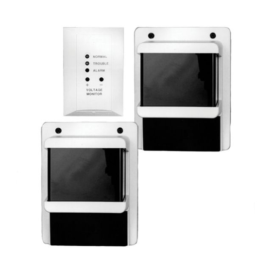
Terminal 8. Wiring a remote indicator A D306 Remote Indicator Plate is shipped with the D296 as a standard accessory. The D306 has three LEDs to indicate the detector’s condition and status and test points for measuring the sensitivity voltage. -
Page 16: Wiring Multiple Detectors
Long-range Beam Smoke Detectors Figure 5.2: Connecting a D306 Remote Indicator Plate 1 D306 Remote Indicator Plate 4 FACP Connector 2 D296/D297 Receiver 5 D306 Remote Indicator Plate 3 EOL resistor 6 Wiring: a=orange, b=blue, c=black, d=red, e=yellow, f=green, g=violet You can wire the D306 a maximum of 500 ft (152 m) from the receiver. -
Page 17: Setup
To allow the transmitter to power up while the cover is off, press the transmitter’s Aim Mode button located above the green LED as indicated in the following figure. Bosch Security Systems, Inc. Installation Instructions 2014.01 | 06 | F.01U.068.899... -
Page 18: Preliminary Alignment
Terminals 1 (–) and 2 (+). If the green LED is steadily lit, you have a faulty transmitter. To begin the process of obtaining a replacement, call the Bosch National Repair Center at (800) 366-2283 or send an e-mail to repair@us.bosch.com. - Page 19 If the optical module is initially aimed too high or too low, adjust the Vertical Fine Tuning adjustment Allen screw (with the supplied Allen wrench) slightly up or down until you see the image. Bosch Security Systems, Inc. Installation Instructions 2014.01 | 06 | F.01U.068.899...
-
Page 20: Fine-Tune Alignment
Notice! This is the most critical alignment process. For the most effective system operation, ensure you have peak voltage during the fine-tune alignment. 2014.01 | 06 | F.01U.068.899 Installation Instructions Bosch Security Systems, Inc. - Page 21 The red and yellow LEDs turn off and the green LED turns steadily on. After some voltage fluctuations, the meter sets to 5.0 VDC. Notice! During this time, do not block the beam or move the units. Bosch Security Systems, Inc. Installation Instructions 2014.01 | 06 | F.01U.068.899...
-
Page 22: Troubleshooting
Flashing Flashing Open Open The sensitivity Set the receiver setting is invalid. to the proper setting. Open Open There is no power. Check for power at Terminals 8 and 2014.01 | 06 | F.01U.068.899 Installation Instructions Bosch Security Systems, Inc. -
Page 23: Receiver - Normal Mode (Cover On)
Setup button. initial beam misaligned or a partial blockage was removed at setup. Flashing Closed Closed Alarm Determine the cause of the alarm and reset the receiver. Bosch Security Systems, Inc. Installation Instructions 2014.01 | 06 | F.01U.068.899... -
Page 24: Maintenance And Testing
– If the cover is on during power‑up, the receiver automatically restarts the internal setup process for a new reference voltage when power is applied. 2014.01 | 06 | F.01U.068.899 Installation Instructions Bosch Security Systems, Inc. -
Page 25: Remote Test
30 sec (5 sec for position 0 or 1), you can determine the approximate sensitivity setting of the installed detector by its response as shown in the following table. Bosch Security Systems, Inc. Installation Instructions 2014.01 | 06 | F.01U.068.899... -
Page 26: Specifications
80% filter Table 8.1: Sensitivity and Response Specifications Electrical Alarm Current (Receiver) D296: 70 mA maximum at 24 VDC D297: 75 mA at 12 VDC Standby Current D296 Receiver: 45 mA at 24 VDC D296 Transmitter: 20 mA at 24 VDC... - Page 27 30 ft (9 m) to 350 ft (107 m) Tamper Receiver: Access door tamper switch in series with trouble contacts. Transmitter: When the cover is removed, the cover tamper switch interrupts transmission Bosch Security Systems, Inc. Installation Instructions 2014.01 | 06 | F.01U.068.899...
- Page 28 Bosch Security Systems, Inc. 130 Perinton Parkway Fairport, NY 14450 www.boschsecurity.com © Bosch Security Systems, Inc., 2014 F.01U.068.899...