Bosch D296 Installation Manual
Long-range beam smoke detectors
Hide thumbs
Also See for D296:
- Installation instructions manual (28 pages) ,
- Application manual (20 pages) ,
- Installation instructions manual (17 pages)
Table of Contents
Advertisement
Quick Links
Advertisement
Table of Contents

Related Manuals for Bosch D296


Summary of Contents for Bosch D296
- Page 1 Long-range beam smoke detectors D296/D297 Installation manual...
-
Page 3: Table Of Contents
Receiver - Aim Mode (cover off) Receiver - Normal Mode (cover on) Maintenance and Testing Fire alarm reset Reference voltage adjustment Cleaning Power outage Remote Test Field sensitivity measurements Specifications Bosch Security Systems, Inc. Installation manual 2017.03 | 7.0 | F.01U.068.899... -
Page 4: Notices
Install, test and maintain the module according to these instructions, NFPA codes, local codes, and the authority having jurisdiction (AHJ). Failure to follow these instructions can result in failure of a detector to initiate an alarm event. Bosch Security Systems, Inc. is not responsible for improperly installed, tested or maintained devices. -
Page 5: System Overview
– Where there are expansive ceilings. One set of D296/D297 detectors can replace up to 24 spot‑type detectors. This saves on service and installation costs, especially in areas such as large offices or department stores. - Page 6 10% If the signal falls below the alarm threshold for the programmed alarm period, the receiver signals an alarm. See the following figure. 2017.03 | 7.0 | F.01U.068.899 Installation manual Bosch Security Systems, Inc.
- Page 7 20 sec. A trouble can be caused by an initial misalignment or the removal of a partial beam blockage during alignment. Perform a fine‑tune alignment. For alignment details, see Setup, page 20. Bosch Security Systems, Inc. Installation manual 2017.03 | 7.0 | F.01U.068.899...
-
Page 8: Installation Considerations
For an illustration of areas in which to avoid exposed lights, see the following figure. Figure 3.1: Avoiding Exposed Lights 1 Receiver 2 Do not place bright lights in this area. 2017.03 | 7.0 | F.01U.068.899 Installation manual Bosch Security Systems, Inc. -
Page 9: Use Correct Wire Gauge And Length
Use the correct wire gauge when installing detectors. D296 Smoke detector, long-range beam 24V For the proper number of D296 transmitter and receiver pairs depending on wire size and length, see the following table. Wire Length Wire Size 14 AWG... -
Page 10: Plan For The Effects Of Stratification In Cold Environments
As illustrated in the following figure, the total obscuration of the infrared beam depends on – the density of the smoke and – width of the smoke cloud along the beam path 2017.03 | 7.0 | F.01U.068.899 Installation manual Bosch Security Systems, Inc. - Page 11 0 or 3 1 or 6 The D296 and D297 can be set for quick response (5 sec) or normal response (30 sec). Some burning materials release hazardous gases along with the smoke. Set the sensitivity for a shorter response times to minimize exposure to the dangerous vapors. Denser smokes allowed to collect for too long, can produce near total obscuration of the detector.
- Page 12 When this type of fire is probable, use sensitivity settings 0 or 1 for a 5-sec response time. For instructions on setting the sensitivity, see Sensitivity setting, page 14. 2017.03 | 7.0 | F.01U.068.899 Installation manual Bosch Security Systems, Inc.
-
Page 13: Mounting
Remove power to all wiring before proceeding. Route the wiring from the electrical box through the wire entrance. If you are going to connect a D344‑RL or D344‑RT to the receiver, route that wiring also. Bosch Security Systems, Inc. Installation manual 2017.03 | 7.0 | F.01U.068.899... -
Page 14: Sensitivity Setting
The indicator, or pointer marking, runs along the side of the switches' shaft as indicated in the following figure. Figure 4.3: Sensitivity Switch 2017.03 | 7.0 | F.01U.068.899 Installation manual Bosch Security Systems, Inc. -
Page 15: Quick Start Installation Flowchart
Long-range beam smoke detectors Mounting | en Quick start installation flowchart Figure 4.4: Installation Flowchart Bosch Security Systems, Inc. Installation manual 2017.03 | 7.0 | F.01U.068.899... -
Page 16: Wiring
Receiver 4 and 5 On fire alarm, normally open (NO) fire alarm contacts terminals close (short). Receiver 6 and 7 On trouble, normally closed (NC) trouble contacts open. terminals 2017.03 | 7.0 | F.01U.068.899 Installation manual Bosch Security Systems, Inc. -
Page 17: Wiring A Remote Indicator
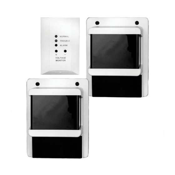
Terminal 8. Wiring a remote indicator A D344‑RL Remote indicator plate is shipped with the D296 as a standard accessory. The D344‑RL has three LEDs to indicate the detector’s condition and status. The indicator plate also has test points for measuring the sensitivity voltage. -
Page 18: Wiring Multiple Detectors
| Wiring Long-range beam smoke detectors Figure 5.3: Connecting a D344-RT Remote Test and Indicator Plate 1 D296/D297 receiver 2 Fire alarm control panel (FACP) 3 Remote indicator plate connector 4 End-of-line resistor 5 Remote test (orange wire) 6 Voltage monitor (blue wire) - Page 19 When two or more adjacent detectors are installed in the same area, alternate the transmitter and receiver locations. If not alternated, ensure the spacing between the detectors is 1/5th the distance from the transmitter to the receiver. Bosch Security Systems, Inc. Installation manual 2017.03 | 7.0 | F.01U.068.899...
-
Page 20: Setup
Terminals 1 (–) and 2 (+). If the green LED is steadily lit, you have a faulty transmitter. Begin the process of obtaining a replacement by: – calling the Bosch National Repair Center at (800) 366-2283 or – sending an e-mail to repair@us.bosch.com Check the three receiver LEDs indicated in the following figure. - Page 21 Fine tune the image to the center of the mirror. It should be aligned with the front and rear bore sights. Use the Horizontal and Vertical Fine Tuning adjustment screws for tuning. Bosch Security Systems, Inc. Installation manual 2017.03 | 7.0 | F.01U.068.899...
-
Page 22: Fine-Tune Alignment
This is the most critical alignment process. For the most effective system operation, ensure you have peak voltage during the fine-tune alignment. Notice! When performing fine-tune alignment, keep your arms and hands out of the beam path. 2017.03 | 7.0 | F.01U.068.899 Installation manual Bosch Security Systems, Inc. - Page 23 3.8 VDC to 4.2 VDC. Use this voltage as a reference when you compare later readings to determine the need for cleaning. If the voltage is not within this range, press the Setup button. Bosch Security Systems, Inc. Installation manual 2017.03 | 7.0 | F.01U.068.899...
- Page 24 | Setup Long-range beam smoke detectors 12. After setup, remove the test cable. 13. Reconnect the remote indicator plate connector, if used. 14. Replace and secure the access door. 2017.03 | 7.0 | F.01U.068.899 Installation manual Bosch Security Systems, Inc.
-
Page 25: Troubleshooting
Open Open The access door is Replace the missing or loose. access door. Open Open Trouble. Beam is Clear the beam blocked or path or realign misaligned. the receiver. Bosch Security Systems, Inc. Installation manual 2017.03 | 7.0 | F.01U.068.899... - Page 26 Closed Open Alarm and Trouble. An Determine the alarm occurred, then cause of the the beam was alarm and reset blocked. the receiver. Clear the beam path. 2017.03 | 7.0 | F.01U.068.899 Installation manual Bosch Security Systems, Inc.
-
Page 27: Maintenance And Testing
With a D344-RT connected to the receiver, use the following procedure to perform a remote test. Insert the operating key and turn the switch to the TEST position for a minimum of 5 sec. Bosch Security Systems, Inc. Installation manual 2017.03 | 7.0 | F.01U.068.899... -
Page 28: Field Sensitivity Measurements
0 or 3 0% (no filter) 60% filter 20% (filter) 60% filter 20% (filter) 80% filter 1 or 6 40% (filter) 80% filter 40% (filter) 80% filter Tab. 8.4: Sensitivity and Response 2017.03 | 7.0 | F.01U.068.899 Installation manual Bosch Security Systems, Inc. -
Page 29: Specifications
Long-range beam smoke detectors Specifications | en Specifications Electrical Alarm Current (Receiver) D296: 70 mA maximum at 24 VDC D297: 75 mA at 12 VDC Standby Current D296 Receiver: 45 mA at 24 VDC D296 Transmitter: 20 mA at 24 VDC D297 Receiver: 50 mA at 12 VDC D297 Transmitter: 20 mA at 12 VDC Operating Voltage D296: 18.0 VDC to 32.0 VDC... - Page 30 Transmission range 30 ft. (9 m) to 350 ft. (107 m) Tamper Receiver: Access door tamper switch in series with trouble contacts. Transmitter: When the cover is removed, the cover tamper switch interrupts transmission 2017.03 | 7.0 | F.01U.068.899 Installation manual Bosch Security Systems, Inc.
- Page 32 Bosch Security Systems, Inc. Bosch Sicherheitssysteme GmbH 130 Perinton Parkway Robert-Bosch-Ring 5 Fairport, NY 14450 85630 Grasbrunn Germany www.boschsecurity.com © Bosch Security Systems, Inc., 2017 F. 0 1U. 0 68. 8 99...