
Related Manuals for Bosch D340


Summary of Contents for Bosch D340
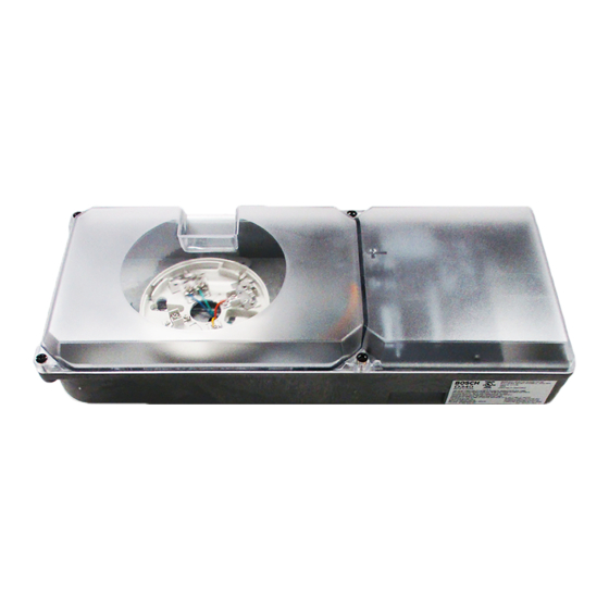
- Page 1 D340 Installation Guide Duct Smoke Detector Housing...
- Page 2 The D340 includes: systems. • One housing, power card, and cover assembly The D340 operates on a two-wire loop, and requires a • Two #10-24 x 1 in. machine screws for mounting smoke detector head. •...
- Page 3 The support hole should be 1 in. to 2 in. (2.5 cm to 5 cm) below the entry hole to allow for possible moisture drainage (Figure 2). Bosch Security Systems, Inc. | 7/09 | F01U071685-06...
- Page 4 For this reason, place the D340 in the range of six to ten times the width of the duct from any uninterrupted run. Refer to Figure 4 and Figure 5.
- Page 5 Remove the screws for later use. 7. Place the two foam gaskets over the sample and exhaust ports on the back of the D340 (Figure 10). DUCT SMOKE DETECTOR MOUNTING TEMPLATE...
- Page 6 D340 | Installation Guide | 5.0 Mounting Figure 12: Wiring Knockout Locations 1 - Wiring Knockouts (5) 2 - Earth ground screw Bosch Security Systems, Inc. | 7/09 | F01U071685-06...
- Page 7 2 - Sample tube 3 - Exhaust tube down stream from sample tube 12. Insert the sample and exhaust tubes into the D340, ensuring the sample tube holes face into the air flow. Ensure the tube alignment point set into the D340.
-
Page 8: Optional External Power (24 Vac/Vdc)
D340 | Installation Guide | 6.0 Selecting the Jumper Figure 20: Reset Jumper w/Remote Display 6.0 Selecting the Jumper Units Location Figure 18 shows the locations of the tamper and reset jumpers on the power card. Figure 18: Jumper Locations... -
Page 9: Dra-5
Figure 23: D344-RL (D306) Wiring detectors have remote alarm indicators. Do not exceed 500 ft (152 m) between the D344-RT (D307) Remote Test/Indicator Plate and the D340. Use 18 AWG (1.2 mm) or larger wire. Figure 22: D340 Two-wire to the D344-RT (D307) Wiring... -
Page 10: Table Of Contents
D340 | Installation Guide | 7.0 Wiring Figure 24: DRA-5 Wiring ALARM 1 - Optional external 4 - Loop (-) power (24 VAC/VDC) 5 - DRA-5 2 - Remote LED 6 - White wire 3 - Loop (+) 7 - Red wire... - Page 11 D340 to Control Panel and External Power Connect the ground to the screw on the ground plate when using grounded three-wire AC wiring. Figure 26: D340 to Control Panel (External Power Required with Remote Test Unit) B B R B B R...
- Page 12 D340 | Installation Guide | 8.0 Installation Testing 7. For duct detectors with the D307 Remote Test 8.0 Installation Testing Indicator installed, reset by moving the keyswitch to the appropriate position and Verify the air flow to ensure the system is properly observing the alarm LED.
-
Page 13: Specifications
6.5 in. x 15.5 in x 4.3 (16.5 cm x 39.5 cm x 11 cm) Dimensions (H x W x D) 22 sec maximum Power-up Time D340 with D344-RT, D344-RL, and External Power Loop Power External Power 8.5 V to 32 V 24 V Condition <... - Page 14 Bosch Security Systems, Inc. 130 Perinton Parkway Fairport, NY 14450-9199 (800) 289-0096 © 2009 Bosch Security Systems, Inc. F01U071685-06...