
Related Manuals for Sony DVF-L700


Summary of Contents for Sony DVF-L700
-
Page 1: Operating Instructions
4-460-309-13 (1) LCD Color View Finder Operating Instructions Before operating the unit, please read this manual thoroughly and retain it for future reference. DVF-L700 © 2013 Sony Corporation... -
Page 2: Table Of Contents
Table of Contents Overview ............3 Usage Notes..........3 Parts Identification ........4 Attaching the Viewfinder to a Camera..6 Detaching the Viewfinder ......7 Adjusting the Position ........8 Adjusting the Display........8 Error Messages ...........9 Cleaning the Screen........9 Specifications ..........10 Table of Contents... -
Page 3: Overview
Overview Usage Notes The DVF-L700 is a 7.0-inch color LCD viewfinder. Place of use This unit has the following features. When using the viewfinder in low temperature environments, dynamic resolution levels may decrease High resolution and wide visual angle during the period immediately after you turn on the The viewfinder uses a 7.0-inch Full HD resolution LCD... -
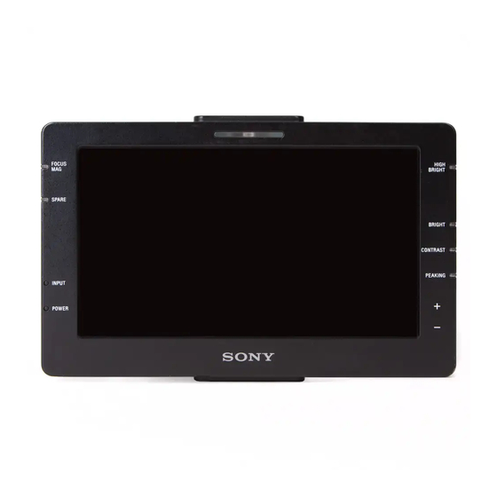
Page 4: Parts Identification
f Ventilation inlet Parts Identification g POWER indicator Lights green when power is being supplied. h INPUT indicator Front Lights green when there is a signal input. The indicator blinks green when the signal format is not supported. i SPARE indicator Lights orange during false color display. - Page 5 z HIGH BRIGHT (high-brightness display) r DC IN connector button When using monitor mode, connect this to an external power supply (10.5 V to 17.0 V DC) using the supplied Brightens the display to improve visibility when shooting power cable (with “STRAIGHT CABLE” label). When outdoors.
-
Page 6: Attaching The Viewfinder To A Camera
Note Depending on the version of your PMW-F5/F55, an image may not be displayed. In such cases, contact a Sony service representative. Attach this unit to the camera using the supplied flexible arm. This unit has a total of three flexible arm attachment points at the top, bottom, and rear of the unit. -
Page 7: Detaching The Viewfinder
Secure the fixing screw. • Fully insert the cable connectors into the connectors and make sure they are secure. If the connector is not firmly connected, the image may Note be distorted and the tally indicator may not light Be sure to use a 1/4-inch screw hole. Using a screw properly. -
Page 8: Adjusting The Position
Adjusting the Position Adjusting the Display You can adjust the height, orientation, and angle of the You can adjust the brightness, contrast, and peaking of viewfinder via the flexible arm’s three joints. the display using the BRIGHT, CONTRAST, and PEAKING buttons. Center joint Allows you to adjust the height by changing the angle of Note... -
Page 9: Error Messages
Error Messages Cleaning the Screen When cleaning the viewfinder’s screen, remove the Display Description viewfinder from the camera, and take care not to damage the components. VF TEMP HIGH Temperature error DEVICE ERROR Device error other than the above For details on how to remove the viewfinder from the camera, see “Detaching the Viewfinder”... -
Page 10: Specifications
Supported formats (during HD-SDI connection) Specifications Total number of scanning lines: 1125 Number of effective scanning lines: 1080 Format Frame rate General 1080/59.94P 59.94 1080/50P Power supply 1080/29.97P 29.97 10.5 V to 17.0 V DC 1080/25P (supplied from the camera or external source) 1080/24P Power consumption 1080/23.98P... - Page 11 DURING THE WARRANTY PERIOD OR AFTER EXPIRATION OF THE WARRANTY, OR FOR ANY OTHER REASON WHATSOEVER. • SONY WILL NOT BE LIABLE FOR CLAIMS OF ANY KIND MADE BY USERS OF THIS UNIT OR MADE BY THIRD PARTIES. • SONY WILL NOT BE LIABLE FOR THE...
- Page 12 Sony Corporation...