
Related Manuals for Metrologic MS2020 Stratos


Summary of Contents for Metrologic MS2020 Stratos
- Page 1 METROLOGIC INSTRUMENTS, INC. MS2020 Stratos Series ® Installation and User’s Guide...
- Page 3 Copyright © 2004 by Metrologic Instruments, Inc. All rights reserved. No part of this work may be reproduced, transmitted, or stored in any form or by any means without prior written consent, except by reviewer, who may quote brief passages in a review, or provided for in the Copyright Act of 1976.
-
Page 4: Table Of Contents
ABLE OF ONTENTS NTRODUCTION Manual Scope ....................1 Manual Symbol Key ..................1 Product Overview ..................... 2 Base Kit Components and Optional Accessories ..........4 Replacement Parts ................... 6 General Precautions..................7 MS2020 Series Design Specifications.............. 8 ODEL HARACTERISTICS MS2020 Scanner/Scale.................. 10 Components .................... - Page 5 ABLE OF ONTENTS Service Access................... 24 Power Installation ..................24 Checkstand Layout Consideration.............. 24 Unpacking the Unit ..................25 Installing the Unit in the Counter ..............26 Proper Lifting Technique ................26 For the MS2020 and the MS2021 (Full Size Units) ........27 For the MS2022 (Compact Size Unit)............
- Page 6 ABLE OF ONTENTS CALE PERATION Scale Zeroing ....................69 Calibration ...................... 70 Tools Required ................... 70 Scale Calibration Methods................70 Priming the Scale for Calibration (lbs. & kg) ..........71 Scale Calibration Procedure (lbs. & kg) with Remote Display ....72 Bar Code Calibration Procedure without Remote Display ......
-
Page 7: Manual Scope
This guide provides an overview of the scanner and scanner/scale operation with ® ® detailed information about setup and installation. Adobe Acrobat versions of the user's manuals are also available for download from the Metrologic website (www.metrologic.com). ANUAL YMBOL Caution! Important Additional Information. -
Page 8: Product Overview
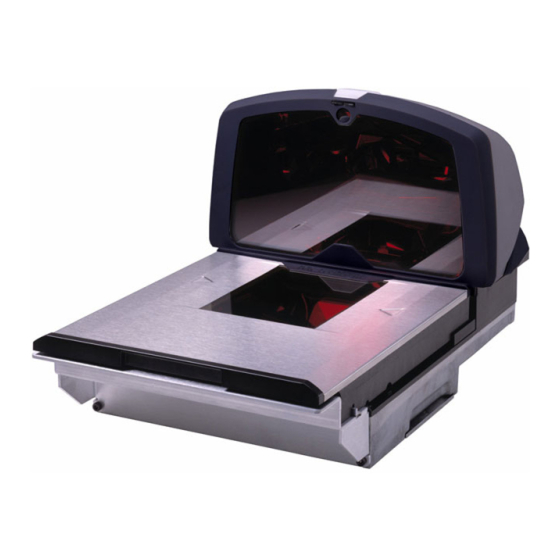
NTRODUCTION RODUCT VERVIEW Metrologic’s Stratos series is designed to meet the demanding needs of high volume supermarket and point-of-sale applications. With advanced features like 6-sided, 360° scanning, 6000 scans per second, a complex scan zone and advanced decoding software, this high performance series of in-counter scanner/scale products guarantees fast customer checkouts with minimal operator fatigue and stress. - Page 9 NTRODUCTION Metrologic's Stratos Series is available in three base models. ODEL ESCRIPTION MS2020-xx Scanner with integrated scale – full size MS2021-xx Scanner only – full size MS2022-xx Scanner only – compact size -xx = Interface type see model number designation for options.
-
Page 10: Base Kit Components And Optional Accessories
Dual Cable Interface 57-57000 Straight, 3.7 m (12') cord with short strain relief Other items may be ordered for the specific protocol being used. To order additional items, contact the dealer, distributor or call Metrologic’s Customer Service Department at 1-800-ID-METRO or 1-800-436-3876. - Page 11 NTRODUCTION OMPONENTS AND PTIONAL CCESSORIES PTIONAL CCESSORIES Part # Description 53-53004 RS232 Aux Cable, Coiled 2.7 m (9') cord 54-54004 RS232 Aux Cable, Straight 2.1 m (7') cord RS232 PowerLink AUX Cable with built in power jack 54-54667 Straight, 2.1 m (7') cord with long strain relief 52-52511 24”...
-
Page 12: Replacement Parts
MS2021 to MS2020 Scale Upgrade / Replacement Kit 46-46890 Wire Seal Conversion Kit Other items may be ordered for the specific protocol being used. To order additional items, contact the dealer, distributor or call Metrologic’s Customer Service Department at 1-800-ID-METRO or 1-800-436-3876. -
Page 13: General Precautions
NTRODUCTION ENERAL RECAUTIONS The following are some general precautions to remember when handling your MS2020 Series scanner. the unit upside down with the platter in place. Figure 2. RESS on the window in the replacement platter or the vertical window frame. Figure 3. -
Page 14: Ms2020 Series Design Specifications
NTRODUCTION MS2020 S ERIES ESIGN PECIFICATIONS Design Specifications Operational Light Source: VLD 650 nm Peak Laser Power: <2.2 mW Horizontal Depth of Field: 0 mm - 152 mm (0”- 6”) for 0.33 mm (13 mil) bar code Vertical Depth of Field: 0 mm - 216 mm (0”- 8.5”) for 0.33 mm (13 mil) bar code Scan Speed: 6000 scans lines per second... - Page 15 NTRODUCTION MS2020 S ERIES ESIGN PECIFICATIONS ONTINUED Design Specifications Scale Capacities Capacity: kg unit 15 kg lb. unit 30.0 lb. Minimum Increment: kg unit 0.005 kg lb. unit 0.01 lb. Maximum Static Weight: kg unit 75 kg lb. unit 150 lb. Adjustments required: Calibration Only Electrical...
-
Page 16: Base Model Characteristics
ODEL HARACTERISTICS MS2020 Scanner/Scale Components Figure 6. MS2020 Components ESCRIPTION Blue and White LEDs Volume/Tone Button (Multi-Function) Scale Zero Button Diamonex or Sapphire Horizontal Window (Laser Aperture) Flow Direction Indicator Stainless Steel Platter (Replaceable) Replaceable Vertical Window with High Impact Frame (Laser Aperture) Debris Guard Speaker Product Weight/Roll Bar... - Page 17 ODEL HARACTERISTICS MS2020 Scanner/Scale Components Figure 7. MS2020 Components ESCRIPTION Power, Scale and EAS Connectors Interface and Aux Scanner Connectors Diagnostic Indicator Display (Located Under Platter) Lift Handles (Located Under Platter) Sealed Calibration Switch/Button Cover (Located Under Platter) On a fully installed unit the calibration switch cover should be sealed with a lead wire or paper seal.
-
Page 18: Dimensions
ODEL HARACTERISTICS MS2020 Scanner/Scale Dimensions Figure 8. MS2020 Dimensions Connector Panel Figure 9. MS2020 Connectors... -
Page 19: Caution And Serial Number Labels
ODEL HARACTERISTICS MS2020 Scanner/Scale Caution and Serial Number Labels Figure 10. MS2020 Label Locations (Top) and Examples (Bottom) -
Page 20: Optional Remote Scale Display
ODEL HARACTERISTICS Optional Remote Scale Display Dimensions Figure 11. Optional Remote Scale Display Dimensions Control Panel Figure 12. Optional Remote Scale Display Controls (46-46816 lb, 46-46820 kg) -
Page 21: Ms2021 Scanner
ODEL HARACTERISTICS MS2021 Scanner Components Figure 13. MS2021 Components ESCRIPTION Blue and White LEDs Volume Button Volume/Tone Button (Multi-Function) Applicable for MS2020 Scanner/Scale Models Only Diamonex or Sapphire Horizontal Window (Laser Aperture) Flow Direction Indicator Stainless Steel Platter (Replaceable) Replaceable Vertical Window with High Impact Frame (Laser Aperture) Debris Guard Speaker Product Roll Bar/Debris Guard... - Page 22 ODEL HARACTERISTICS MS2021 Scanner Components Figure 14. MS2021 Components ESCRIPTION Power and EAS Connectors Interface and Aux Scanner Connectors Diagnostic Indicator Display (Located Under Platter) Lift Handles (Located Under Platter)
-
Page 23: Dimensions
ODEL HARACTERISTICS MS2021 Scanner Dimensions Figure 15. MS2021 Dimensions Connector Panel Figure 16. MS2021 Connectors... -
Page 24: Caution And Serial Number Labels
ODEL HARACTERISTICS MS2021 Scanner Caution and Serial Number Labels Figure 17. MS2021 Label Locations (Top) and Examples (Bottom) -
Page 25: Ms2022 Scanner
ODEL HARACTERISTICS MS2022 Scanner Components Figure 18. MS2022 Components ESCRIPTION Blue and White LEDs Volume/Tone Button (Multi-Function) Applicable for MS2020 Scanner/Scale Models Only Diamonex or Sapphire Horizontal Window (Laser Aperture) Flow Direction Indicator Stainless Steel Platter (Replaceable) Replaceable Vertical Window with High Impact Frame (Laser Aperture) Debris Guard Speaker... - Page 26 ODEL HARACTERISTICS MS2022 Scanner Components Figure 19. MS2022 Components ESCRIPTION Power and EAS Connectors Interface and Aux Scanner Connectors Diagnostic Indicator Display (Located Under Platter) Lift Handles (Located Under Platter)
-
Page 27: Dimensions
ODEL HARACTERISTICS MS2022 Scanner Dimensions Figure 20. MS2022 Connectors Connector Panel Figure 21. MS2022 Connectors... -
Page 28: Caution And Serial Number Labels
ODEL HARACTERISTICS MS2022 Scanner Caution and Serial Number Labels Figure 22. MS2022 Label Locations (Top) and Examples (Bottom) -
Page 29: Installation
Ventilation and Spacing All Stratos models have a die-cast housing to dissipate heat allowing the unit to operate without a ventilation fan. Metrologic recommends that the temperature surrounding the unit does not exceed 40°C (104°F). There should be adequate convection and minimal heat producing equipment in close proximity of the unit. -
Page 30: Service Access
When changing the StratosSWAP optics engine modules, Metrologic recommends removing the unit completely from the checkstand. When calibrating or zeroing the scale, do not remove the unit from the checkstand. -
Page 31: Unpacking The Unit
NSTALLATION NPACKING THE Make sure the shipping box is top-side up before opening. Remove the accessories box and check it's content for the following items. • Remote Display (Optional), Qty. 1 • Programming Guide, Qty. 1 • Installation and User's Guide, Qty. 2 Figure 23. -
Page 32: Installing The Unit In The Counter
NSTALLATION NSTALLING THE NIT IN THE OUNTER Proper Lifting Technique On every Stratos model there are two lifting handles located under the removable platter. These handles are provided to assist in installation when placing the unit in the checkstand cutout. Figure 28. -
Page 33: For The Ms2020 And The Ms2021 (Full Size Units)
NSTALLATION NSTALLING THE NIT IN THE OUNTER For the MS2020 and the MS2021 (Full Size Units) There are two options for mounting your MS2020/MS2021 scanner. Option A, is a two-point mounting system that supports the unit at the front and back. Option B, is a three-point mounting system that supports the unit at the back and on the sides. - Page 34 NSTALLATION NSTALLING THE NIT IN THE OUNTER Option B: Three-point support. Figure 31. Option B, Three-Point Support...
-
Page 35: For The Ms2022 (Compact Size Unit)
NSTALLATION NSTALLING THE NIT IN THE OUNTER For the MS2022 (Compact Size Unit) There are two options for mounting your MS2022 scanner. Option A, is a two- point mounting system that supports the unit at the front and back. Option B, is a three-point mounting system that supports the unit at the back and on the sides. - Page 36 NSTALLATION NSTALLING THE NIT IN THE OUNTER For the MS2022 (Compact Size Unit) Option B: Three-point support. Figure 33. Option B, Three-Point Support...
-
Page 37: Interface
NSTALLATION NTERFACE RS232 Turn off the host system. Connect the RS232 interface cable to the 1 10-pin socket on the bottom of the scanner near the serial number label. Refer to figure 34 on page 33. Connect the other end of the RS232 interface cable to the host device. Before continuing, verify that the RS232 interface cable is connected to the appropriate interface jack on the scanner. - Page 38 NSTALLATION NTERFACE RS232 Scan the recall defaults and enable RS232 bar codes to configure the MS202x for RS232. Scan 1 Recall Defaults ³ Scan 2 Enable RS-232 ³ 10. Turn on the host system.
- Page 39 NTERFACE RS232 Figure 34. RS232 Interface Cable Installation Schematic xxx* Specifies connection to the host. Contact a Metrologic representative for additional information. xx** Specifies international connection. See the Base Kit Components and Optional Accessories section of this guide for a complete listing.
-
Page 40: Full Speed Usb
NSTALLATION NTERFACE USB (I PEED NTEGRATED Turn off the host system. Connect the USB interface cable to the 2 10-pin socket on the bottom of the scanner near the serial number label. Refer to figure 35 on page 36. Connect the other end of the USB interface cable to the host. Before continuing verify that the USB interface cable is connected to the appropriate socket on the scanner. - Page 41 NSTALLATION NTERFACE USB (I PEED NTEGRATED Connect AC power to the transformer. Scan the Enable Full Speed USB Defaults bar code to configure the MS202x for USB communication. Enable Full Speed USB Defaults ³ 10. Turn on the host system. Caution: To maintain compliance with applicable standards, all circuits connected to the scanner must meet the requirements for SELV...
- Page 42 PEED NTEGRATED Figure 35. USB Cable Installation Schematic xxx* Specifies connection to the host. Contact a Metrologic representative for additional information. xx** Specifies international connection. See the Base Kit Components and Optional Accessories section of this guide for a complete listing.
-
Page 43: Low Speed Usb (External With Mx009)
NSTALLATION NTERFACE USB (E MX009) PEED XTERNAL WITH Turn off the host system. Connect the USB/MX009 interface cable to the 2 10-pin socket on the bottom of the scanner near the serial number label. Refer to figure 36 on page 39. Connect the other end of the USB/MX009 interface cable to the host. - Page 44 NSTALLATION NTERFACE USB (E MX009) PEED XTERNAL WITH Connect AC power to the transformer. Scan the Enable USB Defaults bar code to configure the MS202x for USB communication. Enable USB Defaults ³ 10. Scan the Transmit to Converter bar code to configure the MS202x for the MX009.
- Page 45 NSTALLATION NTERFACE USB (E MX009) PEED XTERNAL WITH Figure 36. USB Cable Installation Schematic xx** Specifies international connection. See the Base Kit Components and Optional Accessories section of this guide for a complete listing. Caution: To maintain compliance with applicable standards, all circuits connected to the scanner must meet the requirements for SELV (Safety Extra Low Voltage) according to EN/IEC 60950.
-
Page 46: Ibm 46Xx
NSTALLATION NTERFACE IBM 46 Turn off the host system. Connect the MVC cable to the 1 10-pin socket on the bottom of the scanner near the serial number label. Refer to figure 37 on page 42. Connect the other end of the IBM cable to the host. Before continuing verify that the MVC cable is connected to the appropriate interface jack on the scanner. - Page 47 NSTALLATION NTERFACE IBM 46 Turn on the host system. Scan the Load 46xx IBM Defaults bar code to configure the MS2020 for IBM 46xx communication. Load 46xx IBM Defaults ³ For additional communication options for IBM interfaces refer to the MetroSelect Configruation Guide ( 00-02407).
- Page 48 NTERFACE IBM 46 Figure 37. IBM Cable Installation Schematic Host end connection is application dependent. Contact a Metrologic Customer Service representative for additional information on Metrologic’s MVC Cable series and the host connections available. xx** Specifies international connection. See the Base Kit Components and Optional Accessories section of this guide for a complete listing.
-
Page 49: Ocia
NSTALLATION NTERFACE OCIA Turn off the host system. Connect the OCIA interface cable to the 2 10-pin socket on the bottom of the scanner near the serial number label. Refer to figure 38 on page 45. Connect the other end of the OCIA Interface cable to the host. Before continuing verify that the OCIA cable is connected to the appropriate interface jack on the scanner. - Page 50 NSTALLATION NTERFACE OCIA Turn on the host system. Scan the Load OCIA Defaults bar code to configure the MS2020 for OCIA communication. Load OCIA Defaults ³ For additional communication options for OCIA interfaces refer to the MetroSelect Configuration Guide ( 00-02407).
- Page 51 ERFACE OCIA Figure 38. OCIA Cable Installation Schematic xxx* Specifies connection to the host. Contact a Metrologic representative for additional information. xx** Specifies international connection. See the Base Kit Components and Optional Accessories section of this guide for a complete listing.
-
Page 52: Integrated Scale On Single Cable Scanner/Scale System
If desired to change the scale’s configuration, please contact a Metrologic representative. Scanner/Scale Single Cable RS232 Mode-English 1 Cable English Defaults. - Page 53 NSTALLATION NTEGRATED CALE ON INGLE ABLE CANNER CALE YSTEM 1 Cable USB-English Scanner/Scale Single Cable IBM OEM Full Speed USB, English Defaults. This is full speed USB interface designed to communicate both scanner and scale information to a USB host. Scale parameters will ³...
- Page 54 NSTALLATION NTEGRATED CALE ON INGLE ABLE CANNER CALE YSTEM Changing Scale Defaults The following bar codes change the defaults installed by the bar codes mentioned above. When it is desired to give the English Mode weight in 5 5-Digit Weight digits, as in xx.yyy pounds, scan the “5-digit Weight”...
-
Page 55: Secondary Scanner
If the auxiliary device exceeds this specification an external power supply will be required to power the auxiliary device. The following Metrologic scanners can receive power from Stratos: the MS9520, MS9540, and the MS5145. Turn off the host system. - Page 56 NSTALLATION ECONDARY CANNER Manufacturers Note: Plugging the scanner into the serial port of the PC does not guarantee that scanned information will appear at the PC. A software driver and correct configuration settings are also required for proper communication to occur. Steps 7 through 9 are for MS2020 scanner/scales using dual cable interfaces where the scale is connected to the host with a separate communication cable.
- Page 57 The following bar codes do not apply when using an MS6720 as a secondary scanner. Contact a Metrologic representative for additional information on the MS6720. If the secondary scanner is not a Metrologic scanner refer to Section O of the MetroSelect Configuration Guide. Enable Aux Port ³...
- Page 58 ECONDARY CANNER Figure 39. Secondary Scanner Cable Installation Schematic xxx* Specifies connection to the host. Contact a Metrologic representative for additional information. The MS202x/host cable connection is interface dependent. Refer the installation steps provided for the type of interface required for your application.
-
Page 59: Eas Deactivation
SW1 & SW2 switches 1 and 6 set to ON All models have a connector (marked EAS In) on the bottom of the scanner. Metrologic has available for purchase an EAS cable for connection between the scanner/scale and the Checkpoint Device (optional accessory, 52-52511A). -
Page 60: Scanner Operation Scan Zone
CANNER PERATION Figure 42. Checker-Side (13 mil) Figure 43. Horizontal Left/Right (13 mil) - Page 61 CANNER PERATION Figure 44. Horizontal Direct (13 mil) Figure 45. Vertical Direct (13 mil)
-
Page 62: Ir Activation Area
CANNER PERATION Figure 46. Top-Down (13 mil) IR A CTIVATION Figure 47. IR Activation Area Perpendicular to Package Flow... -
Page 63: Audible
CANNER PERATION NDICATOR ESCRIPTIONS Audible When the MS2020 is in operation, it can provide audible feedback. These sounds indicate the status of the scanner. Eight settings are available for the tone of the beep (normal, 6 alternate tones and no tone) plus three volume settings. -
Page 64: Indicator Descriptions
CANNER PERATION NDICATOR ESCRIPTIONS Visual There is an array of LEDs (white and/or blue) located on the top of the hood of the MS202x. When the scanner is on, the flashing or constant illumination of the LEDs indicates the status of the current scan and the scanner. Figure 48. - Page 65 CANNER PERATION NDICATOR ESCRIPTIONS Visual Flashing Blue then Flashing White This indicates the scanner is in program mode. A razzberry tone indicates that an invalid bar code has been scanned in this mode. If the unit is in sleep mode, each LED will flash once every 15 seconds. Steady White, Blue Off This indicates the scanner may be waiting for communication from the host.
-
Page 66: Failure
CANNER PERATION NDICATOR ESCRIPTIONS Failure Modes Flashing Blue and One Razzberry Tone This indicates that the scanner has experienced a laser subsystem failure. The scanner will try up to 3 times to correct the failure condition. If the laser subsystem continues to fail, that subsystem (horizontal or vertical) will be shut down and an error indication will be shown on the Diagnostic Indicator Display. -
Page 67: Diagnostic Indicator Display
CANNER PERATION NDICATOR ESCRIPTIONS Diagnostic Indicator Display There is a two-digit error code display located under the platter near the bottom right corner of the output window. The following is a list of possible error codes and their meanings. Some errors will require immediate scanner maintenance. Figure 49. - Page 68 CANNER PERATION NDICATOR ESCRIPTIONS Diagnostic Indicator Display Error Description Code SWITCH ERROR – The switch used for volume selection or sleep mode is detected in error (always closed). The condition is self- correcting if possible. If the error persists, return the unit for repair at an authorized service center.
- Page 69 CANNER PERATION NDICATOR ESCRIPTIONS Diagnostic Indicator Display Error Description Code LASER #3 (left horizontal) ERROR – The left laser in the horizontal scanning subsystem denotes a failure. The scanner will try three times to correct the laser operation. If the laser error persists, and the right horizontal laser (#2) is also in error, the horizontal scanning subsystem will be shut down and this error code will remain on the Diagnostic Indicators.
-
Page 70: Power Save Modes
CANNER PERATION OWER ODES The MS2020 has five programmable power save modes. Refer to the MetroSelect Programming Guide for additional information on Power Save Modes. Blink Power Save Mode: Blinks the laser OFF & ON after a programmed period of non-use. When the scanner recognizes a bar code it will exit the Blink mode. - Page 71 CANNER PERATION OWER ODES Dual Action Power Save Mode #2 (Default): Turns the laser OFF after a programmed period of non-use then turns the motor OFF after thirty-minute intervals. Last Laser turns Motor turns Example: Scan If the power save timeout is set to 15 minutes.
-
Page 72: Beeper Options And Button Functions
CANNER PERATION EEPER PTIONS AND UTTON UNCTIONS Changing the Beeper Tone Beeper tones may be programmed directly or incrementally using the following bar code. The new tone will be heard followed by a short pause. Two more new tones will be heard signifying the new setting has been stored in memory. The silent (no beep) tone is also selectable. -
Page 73: The Multi-Function Button
CANNER PERATION EEPER PTIONS AND UTTON UNCTIONS Figure 50. The Multi-Function Volume Button Changing the Beeper Tone hort (<3 second) depression and the beeper volume will change. The new volume will be heard. The silent (no beep) volume is also selectable. -
Page 74: Startup
All MS2020 series scanners have been configured at the factory with a set of default communication protocols. Since many host systems have unique formats and protocol requirements, Metrologic provides a wide range of configurable ® features that may be selected with the use of the MetroSelect... -
Page 75: Scale Operation Scale Zeroing
CALE PERATION CALE EROING After the unit has been officially calibrated (see page 70) the scale can be re-zeroed by pressing the scale zeroing button on either the unit or on the remote display stand. Refer to the figures below for button locations. Figure 54. -
Page 76: Calibration
CALE PERATION ALIBRATION The scanner/scale must be calibrated if: it is a first time installation the scale cannot be re-zeroed the calibration verification tests indicate errors there is a change in the units of measure [i.e. from pounds (lbs.) to kilograms (kg)] if the scale load cell has been replaced the calibration seal is missing or torn The certification of the weighing mechanism of the scale version of this... -
Page 77: Priming The Scale For Calibration (Lbs. & Kg)
CALE PERATION ALIBRATION Priming the Scale for Calibration (lbs. or kg) Prime the scale before either method of calibration is started. Calibrating the scanner/scale must be done after the unit has been installed in the checkstand countertop. It is important to use the correct certified (lb. or kg.) field weight set when calibrating the scale. -
Page 78: Scale Calibration Procedure (Lbs. & Kg) With Remote Display
CALE PERATION ALIBRATION Scale Calibration Procedure (lbs. or kg) with Remote Display Temporarily Remove the platter and place it in a safe location. It is the responsibility of the owner of the scale to confirm compliance with the relevant Weights and Measures statutes and regulations applicable in your area by checking with the appropriate government agency before placing a newly calibrated unit into service or removing any official seals. - Page 79 CALE PERATION ALIBRATION Scale Calibration Procedure (lbs. or kg) with Remote Display Enter full service access mode. Power down the unit if necessary. Press and hold down the Calibration push button then power up the scanner/scale. Release the Calibration push button. Figure 60.
- Page 80 CALE PERATION ALIBRATION Scale Calibration Procedure (lbs. or kg) with Remote Display Make sure there is no load on the scale platter. Calibrate a zero load. Press the right arrow (►) button once when the remote display reads CAL 1 and there is no load on the scale platter. Figure 62.
- Page 81 CALE PERATION ALIBRATION Scale Calibration Procedure (lbs. or kg) with Remote Display 12. Remove the remaining half load from the scale then press clear (C). The message done will flash briefly on the display. Figure 66. 13. Exit calibration mode. Press and hold the test button for at least 3 seconds then release.
-
Page 82: Bar Code Calibration Procedure Without Remote Display
CALE PERATION ALIBRATION Bar Code Calibration Procedure without Remote Display The following calibration procedure can be used when the remote scale display is not present. This procedure requires that the scanner/scale have a software serial number of 15001, or greater. The beeper volume switch is used to advance to the next stage of calibration and the LED display notifies the operator which ‘calibration stage’... - Page 83 CALE PERATION ALIBRATION Bar Code Calibration Procedure without Remote Display Enter the scale program mode. Power down the unit and slide the scale program switch to the program position. If the system is a dual cable system, disconnect the host to scale RS232 cable from the unit. Figure 70.
- Page 84 CALE PERATION ALIBRATION Bar Code Calibration Procedure without Remote Display Make sure there is no load on the scale platter. The white LEDs will be used to indicate the current step in the calibration process. Calibrate a zero load. The white LEDs will blink once periodically. Wait 8 to 10 seconds for scale stability then press the beeper volume switch one time.
- Page 85 CALE PERATION ALIBRATION Bar Code Calibration Procedure without Remote Display Remove half of the load and center the remaining load. The white LEDs will blink four times periodically. Wait for scale stability, and then press the beeper volume switch once. The beeper will beep 4 times indicating that the Cal 4 value has been stored.
-
Page 86: Calibration Verification
CALE PERATION ALIBRATION ERIFICATION U.S. Pounds The following tests verify if the scale's Calibration is accurate. For Kilograms see instructions starting on page 82. The following tests are based on a 2-digit accuracy setting for pounds. Increasing Load Test Shift Test Decreasing Load Test Return to Zero Test Increasing Load Test... - Page 87 CALE PERATION ALIBRATION ERIFICATION U.S. Pounds (lbs.) Shift Test Ensure there is no load on the scale platter and verify the remote display reads 0.00 lbs. Place a 15.00 lb. weight on the scale platter in the center of zone A (see diagram) and verify the remote display reads between 14.99 and 15.01 lbs.
-
Page 88: Kilograms (Kg)
CALE PERATION ALIBRATION ERIFICATION Kilograms (kg) The following tests verify if the scale's Calibration is accurate. For US Pounds see instructions starting on page 80. The following tests are based on a 3-digit accuracy setting for kilograms. Increasing Load Test Shift Test Decreasing Load Test Return to Zero Test... - Page 89 CALE PERATION ALIBRATION ERIFICATION Kilograms (kg) Shift Test Ensure there is no load on the scale platter and verify the remote display reads 0.000 kg. Place a 7.500 kg weight on the scale platter in the center of zone A (see diagram) and verify the remote display reads between 7.495 kg.
-
Page 90: Security Seal Installation
CALE PERATION ECURITY NSTALLATION The certification of the weighing mechanism of the scale version of this scanner is subject to federal, state and local Weights and Measures statutes and regulations and can only be performed by authorized government agencies and/or their duly registered agents. Each time the scale or weighing mechanism is calibrated, it should be properly sealed with a paper seal or a wire seal prior to being placed into service in commerce. - Page 91 CALE PERATION ECURITY NSTALLATION Pressure Sensitive Security Seal Apply the appropriate calibration security seal over the switch cover. Figure 82. Calibration Switch/Button North America Security Seal Placement Figure 83. Calibration Switch/Button Rest of the World Security Seal Placement Reinstall the platter.
-
Page 92: Wire Security Seal (Conversion Kit 46-46890)
CALE PERATION ECURITY NSTALLATION Wire Security Seal (Seal Conversion Kit 46-46890) Temporarily remove the platter and place it in a safe location. Install the calibration switch/button tabbed cover. Secure the cover in place with the flat head Phillips screw provided. Position the security seal cage over the tab on the calibration switch/button cover. -
Page 93: Maintenance Daily Maintenance
AINTENANCE AILY AINTENANCE Smudges and dirt can interfere with the proper scanning of a bar code. Therefore, the output window will need occasional cleaning. For the glass window: Spray glass cleaner onto lint free, non-abrasive cleaning cloth. Gently wipe the scanner window. For the red window: Use mild soap and water with lint free, non-abrasive cleaning cloth. -
Page 94: Vertical Scan Window Replacement
AINTENANCE ERTICAL INDOW EPLACEMENT (MS2022 Shown) Figure 86. Vertical Scan Window Replacement... -
Page 95: Troubleshooting
ROUBLESHOOTING The following guide is for reference purposes only. Contact a Metrologic representative at 1-800-ID-METRO or 1-800-436-3876 to preserve the limited warranty terms. Symptom Possible Cause(s) Solution All Interfaces Check the transformer, outlet No LEDs, beep or No power is being and the power strip. - Page 96 ROUBLESHOOTING Symptom Possible Cause(s) Solution All Interfaces UPC/EAN and Code 128 are The unit is trying to enabled by default. Verify scan a particular that the type of bar code symbology that is not being read has been enabled. selected. The unit powers The unit has been Verify that the bar code that is...
- Page 97 ROUBLESHOOTING Symptom Possible Cause(s) Solution All Interfaces UPC/EAN and Code 128 are The unit is trying to enabled by default. Verify scan a particular that the type of bar code symbology that is not being read has been enabled. selected. The unit powers The unit has been Verify that the bar code that is...
- Page 98 ROUBLESHOOTING Symptom Possible Cause(s) Solution RS232 Only The host is The scanner and host Check that the scanner and receiving data but may not be configured the host are configured for the data does not for the same interface. the same interface. look correct.
-
Page 99: Rs232 Demonstration Program
ROUBLESHOOTING RS232 D EMONSTRATION ROGRAM If an RS232 scanner is not communicating with your IBM compatible PC, key in the following BASIC program to test that the communication port and scanner are working. This program is for demonstration purposes only. It is only intended to prove that cabling is correct, the com port is working, and the scanner is working. -
Page 100: Default Settings
EFAULT ETTINGS OMMUNICATION ARAMETERS Many functions of the scanner can be "programmed" - that is, enabled or disabled. The scanner is shipped from the factory programmed to a set of default conditions. The default parameter of the scanner has an asterisk ( * ) in the charts on the following pages. - Page 101 EFAULT ETTINGS OMMUNICATION ARAMETERS OCIA RS232 ARAMETER EFAULT 46XX MSI-Plessey 10/10 Check Digit MSI-Plessey MOD 10 Check Digit ITF Symbol Lengths Variable ITF Minimum Symbol Length Symbol Length Lock None Minimum Symbol Length Trioptic RSS14 Enable RSS14 ID “]e0” RSS14 App ID “01” RSS14 Check Digit RSS Expanded Enable Expanded ID “]e0”...
- Page 102 EFAULT ETTINGS OMMUNICATION ARAMETERS OCIA RS232 ARAMETER EFAULT 46XX Razzberry Tone on Timeout Three Beeps on Timeout No Beeps on Timeout Fast Beep Beep Twice on Supplements No Beeps on Timeout 5 Retries Before Timeout Timeout In … 2 secs. Laser Off Between Records Variable Laser Off Delay 5 - 635 msec...
- Page 103 EFAULT ETTINGS OMMUNICATION ARAMETERS OCIA RS232 ARAMETER EFAULT 46XX Number of Scan Buffers UPC GTIN-14 Format EAN-8 Enable Transmit EAN-8 Check Digit Convert EAN-8 to EAN-13 EAN-13 Enable Transmit EAN-13 Check Digit UPC-A Enable Convert UPC-A to EAN-13 Transmit UPC-A Check Digit Transmit UPC-A Number System Transmit UPC-A Manufacturers ID.
- Page 104 EFAULT ETTINGS OMMUNICATION ARAMETERS OCIA RS232 ARAMETER EFAULT 46XX Transmit MSI Plessey Check Digits Number of MSI Plessey Check Digits UK Plessey A to X Convert UK Plessey Special 12 Character Format Transmit UK Plessey Check Digit EAN 128 Enable Enable French Pharma Enable Matrix 2 of 5 Check Digit Enable Hong Kong 2 of 5...
- Page 105 Activate on DC2 Character Xmit No Read Message on DC2 Timeout No Transmit LED During No Read Message Programmable “No Read” Message Recv “I” = Transmit “METROLOGIC” Recv “i” = Transmit Scanner ID Byte STX Prefix TAB Prefix Metrologic Prefix UPC Prefix...
- Page 106 EFAULT ETTINGS OMMUNICATION ARAMETERS OCIA RS232 ARAMETER EFAULT 46XX ‘c’ Prefix for UPC ‘$’ Prefix for UPC Programmable Prefix Characters 10 avail Programmable Suffix Characters 10 avail Multiple Predefined Code ID Sets Selections Programmable Prefix for Code Types Programmable Suffix for Code Types Programmable Code Lengths 7 avail Code Selects...
- Page 107 EFAULT ETTINGS OMMUNICATION ARAMETERS OCIA RS232 ARAMETER EFAULT 46XX Bookland Convert Bookland to ISBN Reformat ISBN Transmit ISBN Check Digit Bookland 977 2-Digit Supp Required 378 / 379 Supplements 414 / 419 Supplements 434 / 439 Supplements Number System 2 Enables Supplements Number System 5 Enables Supplements...
- Page 108 EFAULT ETTINGS OMMUNICATION ARAMETERS Default settings for “Aux” interface The secondary scanner and the MS2020 series always communicates via RS232. Data is relayed to the host via various primary interfaces. OCIA RS232 ARAMETER EFAULT 46XX Aux Baud Rate 38400 Aux parity none Aux data bits Aux stop bits...
-
Page 109: Scanner And Cable Terminations
CANNER AND ABLE ERMINATIONS CANNER INOUT ONNECTIONS The MS2020 Series scanner interfaces terminate to 10-pin modular jacks located on the bottom of the units. The serial number label indicates the model number of the scanner. DC Power Function 12VDC Ground 5VDC Function EAS In... - Page 110 CANNER AND ABLE ERMINATIONS CANNER INOUT ONNECTIONS Scanner IBM to Host Scanner RS232 to Host Function Function Ground Ground RS232 TX RS232 TX RS232 RX RS232 RX RS232 RTS RS232 RTS RS232 CTS RS232 CTS RS232 DTR RS232 DTR IBM B- IBM A+ USB or OCIA Auxiliary Port RS232 IN Only...
-
Page 111: Cable Connector Configurations
CANNER AND ABLE ERMINATIONS ABLE ONNECTOR ONFIGURATIONS Cable Connector Configurations (Host End) Cable 54-54xxx MLPN (xxx specifies connection to the host) Function Shield Ground RS232 Transmit Output RS232 Receive Input DTR Input Power/Signal Ground Reserved 9-Pin D-Type Conn. CTS Input RTS Output +5VDC RS232 LSO/AUX Cable... -
Page 112: Laser And Product Safety Notices
ASER AND RODUCT AFETY OTICES This equipment has been tested and found to comply with limits for a Class A digital device, pursuant to part 15 of the FCC Rules. These limits are designed to provide reasonable protection against harmful interference when the equipment is operated in a commercial environment. -
Page 113: Cautions
ASER AND RODUCT AFETY AUTIONS Caution Use of controls or adjustments or performance of procedures other than those specified herein may result in hazardous laser light exposure. Under no circumstances should the customer attempt to service the laser scanner. Never attempt to look at the laser beam, even if the scanner appears to be nonfunctional. -
Page 114: Limited Warranty
In the event that it is determined the equipment failure is covered under this warranty, Metrologic shall, at its sole option, repair the Product or replace the Product with a functionally equivalent unit and return such repaired or replaced Product without charge for service or return freight, whether distributor, dealer/reseller, or retail consumer, or refund an amount equal to the original purchase price. -
Page 115: Patents
ATENTS “Patent Information This METROLOGIC product may be covered by one or more of the following U.S. Patents: U.S. Patent No.; 5,081,34; 5,343,027; 5,627,359; 5,686,717; 5,789,731; 5,828,049; 6,029,894; 6,209,789; 6,299,065 No license right or sublicense is granted, either expressly or by implication,... -
Page 116: Index
NDEX compliance....31, 33, 35, 36, 38, 39, 40, 42, 44, 45, 50, 52, AC .... 5, 24, 31, 34, 35, 37, 38, 72, 76, 108 40, 43, 49, 50 components .. 10, 11, 15, 16, 19, 20 accessories ..4, 5, 25, 33, 36, 39, configuration .... - Page 117 NDEX Operation ........106 operational handles......7, 16, 20, 26 specifications......8 host ....4, 31–53, 58, 59, 68, optics engine module ....6 89–93, 94–102 output window ....61, 87, 88 IBM 46xx ......94–102 parameters......94–102 indicators ........8 parts..........6 audible ........57 patents ........
- Page 118 NDEX stand ...........69 storage ..........9 ventilation........ 9, 23 switch ........11, 53 visual........... 59 cover......72, 76, 84 voltage ..4, 9, 31, 33–40, 42, 43, symbol...........1 44, 45, 49, 50, 52 volume ...... 10, 15, 19, 66 test ...... 14, 68, 70–86, 93 button ........75 warranty ......
- Page 120 May 2004 Printed in the USA 0 0 - 0 2 9 8 3 B...