
Related Manuals for Metrologic MS2420


Summary of Contents for Metrologic MS2420
- Page 1 METROLOGIC INSTRUMENTS, INC. MS2420 Bar Code Scanner / Diva Scale Installation and User’s Guide...
- Page 2 Copyright © 2009 by Metrologic Instruments, Inc. All rights reserved. No part of this work may be reproduced, transmitted, or stored in any form or by any means without prior written consent, except by reviewer, who may quote brief passages in a review, or provided for in the Copyright Act of 1976.
-
Page 3: Table Of Contents
Base Kit Components................................2 Optional Accessories................................2 Optional Remote Scale Display............................3 Dimensions..................................3 Control Panel..................................3 Replacement Parts................................... 4 General Precautions................................. 5 MS2420 Series Design Specifications............................6 ODEL HARACTERISTICS MS2420 Scanner/Diva Scale ..............................7 Components ..................................7 Dimensions................................... 9 Connector Panel................................... 9 Caution and Serial Number Labels............................. - Page 4 ABLE OF ONTENTS CANNER PERATION Scan Zone....................................26 Wake Activation Area (Photocell LED Output) ........................28 Changing the Wake Area Sensitivity Level......................... 29 Indicator Descriptions................................30 Audible ....................................30 Visual ....................................30 Failure ....................................31 Diagnostic Indicator Display; Error Codes .......................... 32 Power Save Modes ................................
- Page 5 ABLE OF ONTENTS CANNER AND ABLE ERMINATIONS Scanner Pinout Connections ..............................65 Cable Connector Configurations ............................67 EGULATORY OMPLIANCE Safety ..................................... 69 EMC ....................................... 70 Weights & Measures ................................71 ..................................72 IMITED ARRANTY ...................................... 73 ATENTS ......................................74 NDEX...
-
Page 7: Introduction
NTRODUCTION ANUAL COPE This guide provides information on the installation, setup and operation of Metrologic’s MS2420 scanner/Diva scale unit. It is designed to be used in conjunction with Metrologic’s MetroSelect Configuration Guide ( 00-02407x) and the MLPN MS2x20 Stratos Series Scanner/Diva Scale Configuration Addendum ( 00-02272x). -
Page 8: Base Kit Components
MS2x 20 Stratos Series Scanner/Diva Scale Configuration Addendum 00-02274x MS2420 Scanner/Diva Scale Installation and User’s Guide Guides also available for download at www.metrologic.com. Other items may be ordered for the specific protocol being used. To order additional items, contact the dealer, distributor or call Metrologic’s Customer Service Department at 1-800-ID-METRO or 1-800-436-3876. -
Page 9: Optional Remote Scale Display
Remote Four Line Scale Display (kg.) (See Figure 2) Other Four Line Scale Display currency lens overlay stickers are available. To order additional items or replacement parts, contact the dealer, distributor or call Metrologic’s Customer Service Department at 1-800-ID-METRO or 1-800-436-3876. Figure 1 Figure 2 * All dimensions are shown in mm (millimeters). -
Page 10: Replacement Parts
Sapphire Platter - Full Size with Product Weight Roll Bar / Platter Lift Handle Other items may be ordered for the specific protocol being used. To order additional items, contact the dealer, distributor or call Metrologic’s Customer Service Department at 1-800-ID-METRO or 1-800-436-3876. -
Page 11: General Precautions
NTRODUCTION ENERAL RECAUTIONS The following are some general precautions to remember when handling your MS2420 series scanner. the unit upside down with the platter in place. Figure 3 on the window in the replacement RESS platter or the vertical window frame. -
Page 12: Ms2420 Series Design Specifications
NTRODUCTION MS2420 S ERIES ESIGN PECIFICATIONS Design Specifications Operational Light Source: VLD 650 nm Peak Laser Power: <1.5 mW Horizontal Depth of Field: 0 mm - 152 mm (0”- 6”) for 0.33 mm (13 mil) Bar Code Vertical Depth of Field: 0 mm - 216 mm (0”- 8.5”) for 0.33 mm (13 mil) Bar Code... -
Page 13: Base Model Characteristics
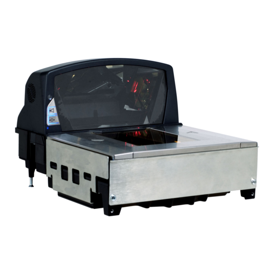
ODEL HARACTERISTICS MS2420 Scanner / Mettler-Toledo DIVA Scale Components Figure 7. MS2420 Components... - Page 14 ODEL HARACTERISTICS MS2420 Scanner / Mettler-Toledo DIVA Scale Components ESCRIPTION OF TEM IN IGURE Scale Zero Button (see page 38) Amber LED, Scale Zero Indicator (see page 38) Volume/Tone Multi-Function Button (see page 36) Blue LED Indicators (see page 30)
-
Page 15: Dimensions
ODEL HARACTERISTICS MS2420 Scanner / Mettler-Toledo DIVA Scale Dimensions Figure 8. MS2420 Dimensions Specifications are subject to change without notice. Connector Panel Figure 9. MS2420 Connector Panel... -
Page 16: Caution And Serial Number Labels
MS2420 Scanner/Diva Scale Caution and Serial Number Labels Figure 10. MS2420 Label Locations (Top) and Examples (Bottom) Caution: To maintain compliance with applicable standards, all circuits connected to the scanner must meet the requirements for SELV (Safety Extra Low Voltage) according to EN/IEC 60950-1. -
Page 17: Installation
Ventilation and Spacing All MS2420 models have a die-cast housing to dissipate heat allowing the unit to operate without a ventilation fan. Metrologic recommends that the temperature surrounding the unit does not exceed 40°C (104°F). There should be adequate convection and minimal heat producing equipment in close proximity of the unit. -
Page 18: Power Installation
• The MS2420 can scan a bar code on five sides of a package. The packages should flow into the scan area that provides the maximum reading performance. No lifting or orientation of the items is necessary. A properly placed item diverter can maximize the flow of packages. -
Page 19: Unpacking The Unit
Remove both cardboard inserts from the box. Figure 12 Lift the MS2420 scanner out of the box by carefully grasping both sides near the center of the unit and lifting directly up. Refer to Figure 13 for hand placement. -
Page 20: Ms2420 Package Warning
NSTALLING THE NIT IN THE OUNTER Before starting to mount the MS2420 determine: • the scanner's orientation in reference to the operator and the direction of package flow, •... -
Page 21: Ms2420 Mounting Diagram
NSTALLATION NSTALLING THE NIT IN THE OUNTER MS2420 Mounting Diagram Figure 17. MS2420 Mounting Diagram Specifications are subject to change without notice. -
Page 22: Cable Installation (Interface Specific)
57-57210x-N-3) MLPN into the 10-pin socket labeled Scanner Host RS232, on the bottom of the MS2420. Refer to the figure on page 17. Connect the other end of the RS232 cable to the proper communication port on the host device. - Page 23 The Recall Defaults bar code is located in the MetroSelect Configuration Guide, under Need to Start Over on page xi ( 00-02407x). MLPN 11. Configure the MS2420 to match the host system’s RS232 parameters. Refer to the MetroSelect Configuration Guide ( 00-02407x) under Section G: RS232 for enabling RS232 MLPN Mode (scan the recall defaults bar code first).
-
Page 24: Full Speed Usb
PECIFIC PEED The following steps describe how to properly install the cables for a Full Speed USB MS2420 application. The scanner/Diva scale must then be configured to match the host’s USB parameters. Cable installation alone does not guarantee that the MS2420 will communicate properly with the host system. -
Page 25: Ibm Oem
These features can only be used for Dual Cable Applications. 11. Configure the MS2420 for USB Serial Emulation Mode or USB Keyboard Emulation Mode by scanning the appropriate configuration bar codes in the USB section of the MetroSelect Configuration Guide (... - Page 26 NSTALLATION ABLE NSTALLATION NTERFACE PECIFIC PEED xx** Specifies international connection. See the Base Kit Components and Optional Accessories section of this guide for a complete listing. See power source caution statement on page 10 of this manual. Figure 19. USB Cable Installation Schematic...
-
Page 27: Ibm 46Xx
IBM 46 The following steps describe how to properly install the cables for an IBM 46xx MS2420 application. The scanner/Diva scale must then be configured to match the host’s IBM 46xx parameters. Cable installation alone does not guarantee that the MS2420 will communicate properly with the host system. - Page 28 PECIFIC IBM 46 Turn on the host system. 10. Configure the MS2420 to match the host system’s IBM 46xx parameters. For Single Cable Applications: The IBM 3 Generation 46xx, English and Metric bar codes are located in the MS2x20 Stratos Series...
-
Page 29: Cable Installation (Secondary Metrologic Scanner)
ETROLOGIC CANNER The following steps describe how to properly install the cables between a secondary Metrologic scanner and the MS2420. The MS2420 and the secondary scanner must then be configured to communicate properly. Cable installation alone does not guarantee that the MS2420 will communicate properly with the host system and secondary scanner. - Page 30 NSTALLATION ABLE NSTALLATION ECONDARY ETROLOGIC CANNER † See Aux power notes on page 23 See power source caution statement on page 10 of this manual. Figure 21. Secondary Scanner Cable Installation Schematic...
-
Page 31: Eas Deactivation
MLPN Figure 22. EAS Cable Connection (Bottom of MS2420) The following figure shows the location of the EAS deactivation area for the MS2420. It is important to pass the entire tag through this area to deactivate the security tag. Figure 23. EAS Deactivation Area... -
Page 32: Scanner Operation Scan Zone
CANNER PERATION Figure 24. Checker-Side (13 mil) Figure 25. Horizontal Left/Right (13 mil) Specifications are subject to change without notice. - Page 33 CANNER PERATION Figure 26. Horizontal Direct (13 mil) Figure 27. Vertical Direct (13 mil) Specifications are subject to change without notice.
-
Page 34: Wake Activation Area (Photocell Led Output)
CTIVATION HOTOCELL UTPUT † The MS2420 scanner’s default power save mode is Dual Action Power Save Mode #2 (see page 35). This power save † mode turns the laser OFF after a configured period of non-use then turns the motor OFF after thirty-minute intervals. -
Page 35: Changing The Wake Area Sensitivity Level
CANNER PERATION LED O CTIVATION ENSITIVITY HOTOCELL UTPUT ANGE Changing the Wake Area Sensitivity Level (Photocell LED Range Adjust) The MS2400 Series bar code scanner wake area sensitivity level can be set to the end users preference by scanning one of the Photocell Sensitivity adjustment bar codes below. -
Page 36: Indicator Descriptions
, the flashing or constant, illumination of the LED indicates the status of the MS2420 and the current scan. There is an additional amber LED next to the scale zero symbol on all MS2420 models that include a scale (see figure below). -
Page 37: Failure
CANNER PERATION NDICATOR ESCRIPTIONS Visual (Continued) Steady Blue and Single blue Flash When the scanner successfully reads a bar code, the blue LED will flash and the scanner will beep once. If the blue LED does not flash or the scanner does not beep once, then the bar code has not been successfully read. Steady Blue After a successful scan, the scanner transmits the data to the host device. -
Page 38: Diagnostic Indicator Display; Error Codes
NDICATOR ESCRIPTIONS Diagnostic Indicator Display There is a two-digit error code display located under horizontal output window near the Metrologic logo on the platter (see figure below). Figure 30. Error Code Display (Optional Product Roll Bar Shown) The following is a list of possible error codes and their meanings. Some errors will require immediate scanner maintenance. - Page 39 CANNER PERATION NDICATOR ESCRIPTIONS Diagnostic Indicator Display RROR ESCRIPTION SCALE ERROR The scanner does not communicate with the scale. Make sure there is nothing plugged into the ‘Scale RS232 to Host’ port. If there is disconnect the cable, it may be causing the communication error. If there is still no communication between the scanner and scale return the unit to authorized service center for repair.
- Page 40 CANNER PERATION NDICATOR ESCRIPTIONS Diagnostic Indicator Display RROR ESCRIPTION Laser #1 (Vertical) Undercurrent Warning – The laser in the vertical scanning subsystem is drawing too little current. The laser is probably not on. This could be the result of a loss of the required set point in memory. Have the unit checked at an authorized service center.
-
Page 41: Power Save Modes
PERATION OWER ODES The MS2420 has five configurable power save modes. Refer to the MetroSelect Configuration Guide for additional information on Power Save Modes. Blink Power Save Mode: Blinks the laser OFF & ON after a configured period of non-use. -
Page 42: Beeper Options And Button Functions
CANNER PERATION EEPER PTIONS AND UTTON UNCTIONS Changing the Beeper Tone Beeper tones may be configured incrementally using the following bar code. The new tone will be heard followed by a short pause. Two more new tones will be heard signifying the new setting has been stored in memory. The silent (no beep) tone is also selectable. -
Page 43: Startup
OWER When a MS2420 scanner is first powered up, it cycles through a number of self-tests before starting normal operation. If there are any initial failures during this sequence of tests the scanner will beep or razz to indicate the error and an error code will appear in the diagnostic indicator display. -
Page 44: Scale Operation Scale Zeroing
CALE PERATION CALE EROING After the unit has been officially calibrated (see page 39) the scale can be re-zeroed by pressing the scale zeroing button on either the unit or on the remote display stand. When the scale is at zero the amber LED will be illuminated. Figure 35. -
Page 45: Calibration
A bar code is used to initiate the calibration sequence and the Multi-Functional Button (see page 36) is used to store critical range values. This calibration procedure will work with the remote display connected to the MS2420 but no data will appear on the remote display. -
Page 46: Priming The Scale For Calibration (Lbs. & Kg)
CALE PERATION ALIBRATION Priming the Scale for Calibration (lbs. or kg) Prime the scale before starting either method of calibration. Calibrate the scanner/Diva scale after the unit is installed in the checkout countertop. It is important to use the correct certified (lb. or kg.) field weight set when calibrating the scale. Check the platter to ensure that nothing is interfering with its freedom to move. -
Page 47: Scale Calibration Procedure (Lbs. & Kg) With Remote Display
Place the security screw and cover in a safe location. Figure 41. Diva Scale security seals Press the calibration button to access the Service Mode. ‘Cal’ then ‘Conf’ will appear on the remote display. Figure 42. Enter Service Mode * These procedures are for MS2420 Scanner/Diva Scale models only... - Page 48 (0 to 15kg) kg multi-interval (0 to 6kg, 6 to 15kg) ** lbs multi-interval (0 to 15 lbs, 15 to 30 lbs) Common ranges used as default setting. * These procedures are for MS2420 Scanner/Diva Scale models only...
- Page 49 17. The unit’s calibration must now be verified as required by state and/or local Weight and Measures regulations (starting on Page 48). Need to Start Over? If for any reason you need to restart the calibration process, restart at Step 1 on page 41. * These procedures are for MS2420 Scanner/Diva Scale models only...
-
Page 50: Bar Code Calibration Procedure Without Remote Display
Enter the scale program mode. Press the calibration button to engage the scale calibration mode. If the system is a dual cable system, disconnect the host to scale RS232 cable from the unit. Figure 46. Entering the Scale Program Mode * These procedures are for MS2420 Scanner/Diva Scale models only... - Page 51 ALIBRATION Bar Code Calibration Procedure without Remote Display* Reinstall the platter onto the MS2420 scanner/Diva scale (see Figure 47). Figure 47. Platter Installation Enter bar code calibration mode. Use the vertical window to scan one of the following bar codes, whichever weight units (either pounds or kilograms) the scanner/Diva scale will be operating in.
- Page 52 Figure 49. Entering Bar Code Calibration Mode (Kilograms) If a razz tone sounds, an error has occurred. Refer to Diagnostic Indicator Display; Error Codes starting on page 32 for additional information. * These procedures are for MS2420 Scanner/Diva Scale models only...
- Page 53 Step 1 on page 44. 12. The unit’s calibration must now be verified as required by state and/or local Weight and Measures regulations (starting on Page 48). * These procedures are for MS2420 Scanner/Diva Scale models only...
-
Page 54: Calibration Verification
CALE PERATION ALIBRATION ERIFICATION U.S. Pounds (lbs.) The following tests verify if the scale's Calibration is accurate. For Kilograms see instructions starting on page 49. The following tests are based on a 2-digit accuracy setting for pounds. Increasing Load Test Shift Test Decreasing Load Test Return to Zero Test... -
Page 55: Kilograms (Kg)
CALE PERATION ALIBRATION ERIFICATION Kilograms (kg) The following tests verify if the scale's Calibration is accurate. For US Pounds see instructions starting on page 48. The following tests are based on a 3-digit accuracy setting for kilograms. Increasing Load Test Shift Test Decreasing Load Test Return to Zero Test... -
Page 56: Security Seal Installation
With very light pressure, push down on the adhesive calibration security seal label to ensure a firm adhesion is created (see Figure 56). Figure 56. Reinstall the platter. Figure 57. Platter Installation * These procedures are for MS2420 Scanner/Diva Scale models only... -
Page 57: Wire Security Seal (Conversion Kit 46-00359)
Leaving the least amount of slack in the wire loop as possible, close the wire seal and verify the seal connection is secure. Reinstall the platter. Figure 59. Platter Installation * These procedures are for MS2420 Scanner/Diva Scale models only... -
Page 58: Maintenance
AINTENANCE ORIZONTAL INDOW EPLACEMENT Figure 60. Platter/Horizontal Scan Window Replacement * See replacement parts on page 4. -
Page 59: Daily Maintenance
AINTENANCE AILY AINTENANCE Smudges and dirt can interfere with the proper scanning of a bar code. Therefore, the horizontal and vertical output windows will need occasional cleaning. For the glass window: Spray glass cleaner onto lint free, non-abrasive cleaning cloth. Gently wipe the scanner window. -
Page 60: Troubleshooting
ROUBLESHOOTING The following guide is for reference purposes only. Contact a Metrologic representative at 1-800-ID-METRO or 1-800-436-3876 to preserve the limited warranty terms. Symptom Possible Cause(s) Solution All Interfaces No LEDs, beep or motor No power is being Check the transformer, outlet and the power strip. Make sure the spin. - Page 61 ROUBLESHOOTING Symptom Possible Cause(s) Solution All Interfaces The scanner is The unit scans a bar configured to support If the scanner is setup to support ACK/NAK, RTS/CTS, XON/XOFF or code, but locks up after some form of host D/E, verify that the host cable and host are supporting the the first scan (the blue handshaking but is not handshaking properly.
- Page 62 The auxiliary input port’s data format must match the main output format of the secondary scanner. * Refer to the MS2x20 Stratos Series Scanner/Diva Scale Configuration Addendum ( 00-02272x) under MLPN Scanner Configuration Bar Codes: Auxiliary Port, Quick Start for a Secondary Metrologic Scanner.
-
Page 63: Rs232 Demonstration Program
ROUBLESHOOTING RS232 D EMONSTRATION ROGRAM If an RS232 scanner is not communicating with your IBM compatible PC, key in the following BASIC program to test that the communication port and scanner are working. This program is for demonstration purposes only. It is only intended to prove that cabling is correct, the com port is working, and the scanner is working. -
Page 64: Default Settings
EFAULT ETTINGS OMMUNICATION ARAMETERS Many functions of the scanner can be "configured" - that is, enabled or disabled. The scanner is shipped from the factory pre- configured to a set of default conditions. The default parameter of the scanner has an asterisk ( * ) in the charts on the following pages. - Page 65 EFAULT ETTINGS OMMUNICATION ARAMETERS RS232 IBM 46 ARAMETER EFAULT RSS Expanded Enable Expanded ID “]e0” RSS Limited Enable RSS Limited ID “]e0” RSS Limited App ID “01” RSS Limited Check Digit DTS/SIEMENS DTS/NIXDORF NCR F NCR S Beeper Tone Normal Beep Transmit Sequence Before Transmit Beeper Volume...
- Page 66 EFAULT ETTINGS OMMUNICATION ARAMETERS RS232 IBM 46 ARAMETER EFAULT Dual Action Power Save Mode #1 Dual Action Power Save Mode #2 Same Symbol Rescan Timeout: 500 msecs Configurable in 50 msec steps (MAX 6.35 seconds) Intercharacter Delay Configurable in 1 msecs 1 msec steps (MAX 255 msecs) 10 msecs in KBW Number of Scan Buffers...
- Page 67 Razz on ‘z’ CTS Scan Transmit Enable Limit 1 Scan per CTS Activate on DTR Activate on DC2 Character Xmit No Read Message on DC2 Timeout No Transmit LED During No Read Message Configurable “No Read” Message Recv “I” = Transmit “METROLOGIC”...
- Page 68 OMMUNICATION ARAMETERS RS232 IBM 46 ARAMETER EFAULT Recv “i” = Transmit Scanner ID Byte STX Prefix TAB Prefix Metrologic Prefix UPC Prefix ETX Suffix TAB Suffix Carriage Return Suffix Line Feed Suffix UPC Suffix Transmit LRC Start LRC on 1...
- Page 69 EFAULT ETTINGS OMMUNICATION ARAMETERS RS232 IBM 46 ARAMETER EFAULT Two Digit Redundancy Five Digit Redundancy Enable Coupon Code 128 Transmit Coupon ‘]C1’ Group Separator Coupon Code Can Begin with ’4’ Enable EAN-99 Coupon Code Bookland Supplements French 378/379 Supplements German 434/439 Supplements Convert Bookland to ISBN Bookland 979 Supplements Convert 979 to ISBN...
- Page 70 EFAULT ETTINGS OMMUNICATION ARAMETERS Default settings for “Aux” interface The secondary scanner and the MS2420 series always communicates via RS232. Data is relayed to the host via various primary interfaces RS232 IBM 46 ARAMETER EFAULT Aux Baud Rate 38400 Aux Parity...
-
Page 71: Scanner And Cable Terminations
CANNER AND ABLE ERMINATIONS CANNER INOUT ONNECTIONS The MS2420 scanner terminates to 10-pin modular jacks located on the bottom of the unit. The serial number label indicates the model number and interface of the scanner. DC Power Function Function EAS In... - Page 72 INOUT ONNECTIONS There are four additional 10-pin modular jacks located on the bottom of the of the MS2420 scanner models that may be used for an integrated scale application and the use of a remote display. Please keep in mind that every application is unique. The use of these connections depends on the specifications of the scale’s manufacturer.
-
Page 73: Cable Connector Configurations
Non-Locking, Type A Type A Ground 57-57227x-N-3 57-57201x-N-3 IBM 46xx Cable, 57-57212x-N-3 MLPN Function** Signal Ground IBM +A IBM -B 4-Pin SDL No Connect ** All signals are referenced from the MS2420 scanner. Specifications are subject to change without notice. - Page 74 10-Position Modular Plug Shield Ground * This configuration cable was designed to be used with the MS2420 auxiliary connector only. ** All signals are referenced from the MS2420 scanner. † All signals are referenced from the auxiliary / secondary scanner.
-
Page 75: Regulatory Compliance
EGULATORY OMPLIANCE AFETY ITE Equipment IEC 60950-1; EN 60950-1 Laser Laser Class 1: IEC 60825-1:1993+A1+A2, EN: 60825-1:1994+A1+A2 Caution Use of controls or adjustments or performance of procedures other than those specified herein may result in hazardous laser light exposure. Under no circumstances should the customer attempt to service the laser scanner. Never attempt to look at the laser beam, even if the scanner appears to be nonfunctional. -
Page 76: Emc
EGULATORY OMPLIANCE Emissions: FCC Part 15, ICES-003, CISPR 22, EN 55022 Immunity: CISPR 24, EN 55024 Class A Devices The following is applicable when the scanner cable is greater in length than 3 meters (9.8 feet) when fully extended: Les instructions ci-dessous s’appliquent aux cables de scanner dépassant 3 métres (9.8 pieds) de long en extension maximale: Folgendes trifft zu, wenn das Scannerkabel länger als 3 Meter ist: This equipment has been tested and found to comply with limits for a Class A digital device, pursuant to part 15 of the FCC... -
Page 77: Weights & Measures
EGULATORY OMPLIANCE Class B Devices The following is applicable when the scanner cable is less than 3 meters (9.8 feet) in length when fully extended: Les instructions ci-dessous s’appliquent aux cables de scanner ne dépassant pas 3 métres (9.8 pieds) de long en extension maximale: Folgendes trifft zu, wenn das Scannerkabel kürzer als 3 Meter ist: This device complies with Part 15 of the FCC Rules. -
Page 78: Limited Warranty
(2) year limited warranty from the date of manufacture. Metrologic warrants and represents that all MS2420 series scanners are free of all defects in material, workmanship and design, and have been produced and labeled in compliance with all applicable U.S. -
Page 79: Patents
ATENTS Patent Information This METROLOGIC product may be covered by, but not limited to, one or more of the following U.S. Patents: U.S. Patent No.; 5,343,027; 5,627,359; 5,686,717; 5,789,731; 5,828,049; 6,029,894; 6,209,789; 6,299,065; 6,345,505; 6,422,467; 6,481,625; 6,494,377; 6,814,292; 6,830,190; 6,874,690; 6,918,540; 6,951,304;... -
Page 80: Index
NDEX modes ..............30, 31 finger recess ..............5 AC ..............see power full service access mode ..........42 amber LED ............see indicators function ..........54, 61, 62, 63, 65–68 application ..............32, 57 audible............see indicators AUX...............8, 56, 65 ground...............65–68 beep ..............see indicators blue LED ............see indicators host .......... - Page 81 NDEX razzberry tone .............30, 31, 59 test ..............37, 39–51 regulatory compliance ..........69–71 tone ............30, 36, See button remote display ............3, 42, 49 transformer............see power repair .............31, 32, 33, 72 troubleshooting............54–57 RS232 ..............17, 58–64 unit of measure ............48, 49 safety.................70, 71 USB................58–64 scale................8, 11 Scale ................66...
- Page 84 January 2009, Version 03 0 0 - 0 5 3 1 0 A...