Vulcan-Hart SG4D ML-114875 Service Manual
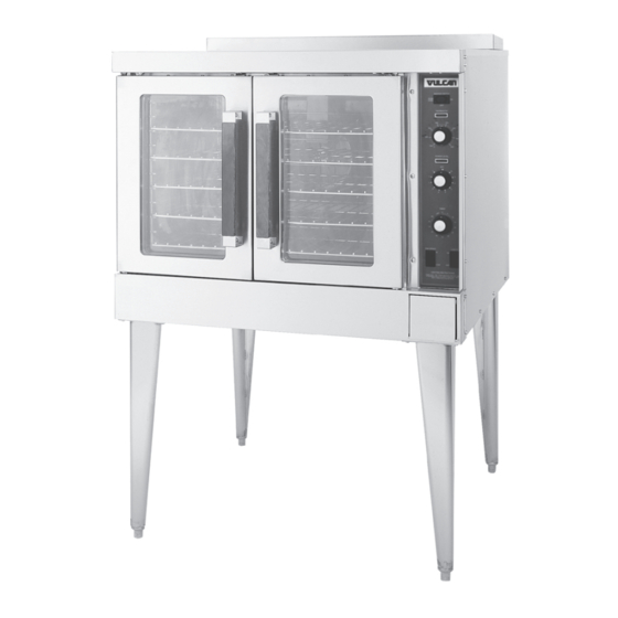
Sg4 series full size gas convection oven; sg6 series full size gas convection oven
Hide thumbs
Also See for SG4D ML-114875:
- Installation & operation manual (56 pages) ,
- Service manual (44 pages) ,
- Installation & operation manual (24 pages)
Table of Contents
Advertisement
Quick Links
Model SG4D
THIS MANUAL IS PREPARED FOR THE USE OF TRAINED VULCAN SERVICE TECHNICIANS
AND SHOULD NOT BE USED BY THOSE NOT PROPERLY QUALIFIED. IF YOU HAVE ATTENDED
A VULCAN SERVICE SCHOOL FOR THIS PRODUCT, YOU MAY BE QUALIFIED TO PERFORM
ALL PROCEDURES DESCRIBED IN THIS MANUAL.
THIS MANUAL IS NOT INTENDED TO BE ALL ENCOMPASSING. IF YOU HAVE NOT ATTENDED
A VULCAN SERVICE SCHOOL FOR THIS PRODUCT, YOU SHOULD READ, IN ITS ENTIRETY,
THE REPAIR PROCEDURE YOU WISH TO PERFORM TO DETERMINE IF YOU HAVE THE
NECESSARY TOOLS, INSTRUMENTS AND SKILLS REQUIRED TO PERFORM THE
PROCEDURE. PROCEDURES FOR WHICH YOU DO NOT HAVE THE NECESSARY TOOLS,
INSTRUMENTS AND SKILLS SHOULD BE PERFORMED BY A TRAINED VULCAN SERVICE
TECHNICIAN.
REPRODUCTION OR OTHER USE OF THIS MANUAL, WITHOUT THE EXPRESS WRITTEN
CONSENT OF VULCAN-HART COMPANY, IS PROHIBITED.
VULCAN-HART COMPANY, P.O. BOX 696, LOUISVILLE, KY 40201-0696, TEL. (502) 778-2791
SERVICE MANUAL
SG4 & SG6 SERIES
FULL SIZE GAS
CONVECTION OVENS
MODELS
SG4D
SG4C
SG6D
SG6C
NOTICE
– 1 –
ML-114875
ML-114876
ML-114877
ML-114878
FORM 31192 (Jan. 2002)
Advertisement
Table of Contents

Related Manuals for Vulcan-Hart SG4D ML-114875


Summary of Contents for Vulcan-Hart SG4D ML-114875
- Page 1 INSTRUMENTS AND SKILLS SHOULD BE PERFORMED BY A TRAINED VULCAN SERVICE TECHNICIAN. REPRODUCTION OR OTHER USE OF THIS MANUAL, WITHOUT THE EXPRESS WRITTEN CONSENT OF VULCAN-HART COMPANY, IS PROHIBITED. VULCAN-HART COMPANY, P.O. BOX 696, LOUISVILLE, KY 40201-0696, TEL. (502) 778-2791 – 1 – FORM 31192 (Jan. 2002)
- Page 2 © VULCAN-HART COMPANY, 2002 – 2 –...
-
Page 3: Table Of Contents
TABLE OF CONTENTS GENERAL ................................5 Introduction ............................... 5 Installation ..............................5 Operation ..............................5 Cleaning ..............................5 Lubrication ..............................5 Specifications ............................5 Electrical Data ............................ 5 Gas Data ............................. 5 Tools ................................. 5 Standard ............................. 5 Special ..............................5 REMOVAL AND REPLACEMENT OF PARTS ..................... - Page 4 TABLE OF CONTENTS (Cont.) Computer Controller (SG4C/SG6C) ......................23 Operation ............................23 Setup Mode ............................23 Probe Test ............................23 Solid State Relay Test ........................24 Computer Controller Calibration (SG4C/SG6C) ..................24 Calibration Steps ..........................24 Gas Pressure Adjustment ........................25 Verification of Spark at Igniter ........................ 26 Door Switch Adjustment ..........................26 Blower Adjustment ...........................27 Door Adjustment ............................28...
-
Page 5: General
GENERAL INTRODUCTION Procedures in this manual will apply to all models unless specified. Pictures and illustrations can be of any model unless the picture or illustration needs to be model specific. All models are equipped with a two-speed HP electric motor, porcelain interior and two 30,000 BTU/hr burners as standard equipment. -
Page 6: Removal And Replacement Of Parts
REMOVAL AND REPLACEMENT OF PARTS COMPONENT LOCATION TOP VIEW BLOWER MOTOR OVEN LIGHTS COOLING TEMPERATURE PROBE COMPONENT GAS BURNERS PANEL IGNITER & GAS VALVE FLAME SENSE DOOR CONTROL SWITCH PANEL HIGH LIMIT PL-56044 – 6 –... -
Page 7: Covers And Panels
Control Panel COVERS AND PANELS 1. Remove three screws on the right side which secure the control panel. Pull the panel away WARNING: DISCONNECT (UNPLUG) ELECTRICAL from the oven. POWER SUPPLY AND PLACE A TAG AT THE DISCONNECT SWITCH INDICATING YOU ARE WORKING ON THE CIRCUIT. -
Page 8: Control Panel Components
CONTROL PANEL COMPONENTS M A S T E R S W I T C H O N / H E A T I N D I C A T O R L I G H T S N O I G N I T I O N L I G H T C O M P U T E R C O N T R O L L E R... -
Page 9: Component Panel Components
COMPONENT PANEL COMPONENTS PORCELAIN PORCELAIN BLOCK BLOCK ASSEMBLY ASSEMBLY TRANSFORMER TRANSFORMER MOTOR HEATING CONTROL RELAY RELAYS IGNITION IGNITION MODULE MODULE BOARD BOARD IGNITION IGNITION MODULE MODULE HEATING RELAY PORCELAIN PORCELAIN BLOCK BLOCK ASSEMBLY ASSEMBLY SG4D/SG6D PL-56047 SG4C/SG6C PL-56048 Procedure WARNING: DISCONNECT (UNPLUG) ELECTRICAL POWER SUPPLY AND PLACE A TAG AT THE DISCONNECT SWITCH INDICATING YOU ARE WORKING ON THE CIRCUIT. -
Page 10: Temperature Probe
7. Remove the probe from the bracket(s). TEMPERATURE PROBE WARNING: DISCONNECT (UNPLUG) ELECTRICAL POWER SUPPLY AND PLACE A TAG AT THE DISCONNECT SWITCH INDICATING YOU ARE WORKING ON THE CIRCUIT. 1. Remove the right-side panel as outlined under Covers and Panels. 2. -
Page 11: Gas Burners
GAS BURNERS 5. Reverse the procedure to install and check for proper operation. WARNING: DISCONNECT (UNPLUG) ELECTRICAL A. Ensure the spacers are in place on the POWER SUPPLY AND PLACE A TAG AT THE ignition wires. The spacers are intended DISCONNECT SWITCH INDICATING YOU ARE to keep the ignition wires from laying flat WORKING ON THE CIRCUIT. -
Page 12: Gas Orifice
3. Disconnect compression fittings from the GAS ORIFICE valve. WARNING: DISCONNECT (UNPLUG) ELECTRICAL POWER SUPPLY AND PLACE A TAG AT THE DISCONNECT SWITCH INDICATING YOU ARE WORKING ON THE CIRCUIT. WARNING: SHUT OFF THE GAS BEFORE SERVICING THE OVEN. 1. Remove the lower front cover as outlined under Covers and Panels. -
Page 13: Ignition Control Module
IGNITION CONTROL MODULE SPARK IGNITER AND FLAME SENSE WARNING: DISCONNECT (UNPLUG) ELECTRICAL WARNING: DISCONNECT (UNPLUG) ELECTRICAL POWER SUPPLY AND PLACE A TAG AT THE POWER SUPPLY AND PLACE A TAG AT THE DISCONNECT SWITCH INDICATING YOU ARE DISCONNECT SWITCH INDICATING YOU ARE WORKING ON THE CIRCUIT. -
Page 14: Blower And Motor
4. If replacing: BLOWER AND MOTOR A. Blower Only - Loosen set screws on blower hub and using a bearing puller, WARNING: DISCONNECT (UNPLUG) ELECTRICAL remove blower from motor shaft. POWER SUPPLY AND PLACE A TAG AT THE DISCONNECT SWITCH INDICATING YOU ARE 1) Reverse procedure to install and WORKING ON THE CIRCUIT. -
Page 15: Oven Doors And Bearings
OVEN DOORS AND BEARINGS FRONT VIEW OF MOTOR FROM INSIDE OVEN CAVITY WARNING: DISCONNECT (UNPLUG) ELECTRICAL POWER SUPPLY AND PLACE A TAG AT THE DISCONNECT SWITCH INDICATING YOU ARE WORKING ON THE CIRCUIT. 1. Remove the top front cover and bottom front cover as outlined under Covers and Panels. -
Page 16: Door Catch Assembly
7. The top and bottom bearings are now DOOR WINDOW accessible for inspection and/or replacement if needed. WARNING: DISCONNECT (UNPLUG) ELECTRICAL A. If bearings are OK, proceed to step 8. POWER SUPPLY AND PLACE A TAG AT THE DISCONNECT SWITCH INDICATING YOU ARE B. -
Page 17: Door Switch
DOOR SWITCH HIGH LIMIT THERMOSTAT WARNING: DISCONNECT (UNPLUG) ELECTRICAL WARNING: DISCONNECT (UNPLUG) ELECTRICAL POWER SUPPLY AND PLACE A TAG AT THE POWER SUPPLY AND PLACE A TAG AT THE DISCONNECT SWITCH INDICATING YOU ARE DISCONNECT SWITCH INDICATING YOU ARE WORKING ON THE CIRCUIT. WORKING ON THE CIRCUIT. -
Page 18: Interior Lights
3. Disconnect the lead wires from the high limit INTERIOR LIGHTS thermostat. Remove the high limit thermostat from the cover mounting plate. WARNING: DISCONNECT (UNPLUG) ELECTRICAL POWER SUPPLY AND PLACE A TAG AT THE DISCONNECT SWITCH INDICATING YOU ARE WORKING ON THE CIRCUIT. 1. -
Page 19: Lamp Assembly
Lamp Assembly COOLING FAN 1. Remove the lens and bulb. WARNING: DISCONNECT (UNPLUG) ELECTRICAL 2. Remove the springs from the retaining tabs POWER SUPPLY AND PLACE A TAG AT THE (two places) on the socket. DISCONNECT SWITCH INDICATING YOU ARE WORKING ON THE CIRCUIT. -
Page 20: Service Procedures And Adjustments
SERVICE PROCEDURES AND ADJUSTMENTS WARNING: CERTAIN PROCEDURES IN THIS SECTION REQUIRE ELECTRICAL TEST OR MEASUREMENTS WHILE POWER IS APPLIED TO THE MACHINE. EXERCISE EXTREME CAUTION AT ALL TIMES. IF TEST POINTS ARE NOT EASILY ACCESSIBLE, DISCERN POWER, ATTACH TEST EQUIPMENT AND REAPPLY POWER TO TEST. -
Page 21: Solid State Temperature Controller Test (Sg4D/Sg6D)
8. Check relay voltages on the board: SOLID STATE TEMPERATURE CONTROLLER TEST A. For 120 VAC controls - check across (SG4D/SG6D) terminals 7 & 9 for input to the internal relay and 6 & 9 for output from the internal relay. WARNING: DISCONNECT (UNPLUG) ELECTRICAL POWER SUPPLY AND PLACE A TAG AT THE B. -
Page 22: Temperature Probe Test (Sg4D/Sg6D)
TEMPERATURE PROBE TEST (SG4D/SG6D) WARNING: DISCONNECT (UNPLUG) ELECTRICAL POWER SUPPLY AND PLACE A TAG AT THE DISCONNECT SWITCH INDICATING YOU ARE WORKING ON THE CIRCUIT. The temperature probe used in conjunction with the Solid State Temperature controller is an RTD (resistance temperature detector) of the Thermistor type. -
Page 23: Computer Controller (Sg4C/Sg6C)
3. Listed are the parameters and data in the COMPUTER CONTROLLER setup mode. (SG4C/SG6C) Operation Refer to the Installation & Operation Manual for specific operating instructions. Setup Mode Use the setup mode to verify that the control is configured to the factory settings which result in the proper operation of the oven. -
Page 24: Solid State Relay Test
Solid State Relay Test C. Press the set key again to save the change, then exit the temperature set mode. 1. Remove the right side panels as outlined under Covers and Panels in Removal and 4. Allow the oven temperature to stabilize Replacement of Parts. -
Page 25: Gas Pressure Adjustment
4. Install hose barb adapter and attach GAS PRESSURE ADJUSTMENT manometer tube. WARNING: DISCONNECT (UNPLUG) ELECTRICAL POWER SUPPLY AND PLACE A TAG AT THE DISCONNECT SWITCH INDICATING YOU ARE WORKING ON THE CIRCUIT. Accurate gas pressure adjustments can only be made with the gas on and the burner lit. -
Page 26: Verification Of Spark At Ignitor
WARNING: THE FOLLOWING STEPS REQUIRE VERIFICATION OF SPARK AT IGNITOR POWER TO BE APPLIED TO THE UNIT DURING THE TEST. USE EXTREME CAUTION AT ALL TIMES. WARNING: DISCONNECT (UNPLUG) ELECTRICAL POWER SUPPLY AND PLACE A TAG AT THE 4. Plug the oven in and set the temperature DISCONNECT SWITCH INDICATING YOU ARE controller to the maximum setting. -
Page 27: Blower Adjustment
BLOWER ADJUSTMENT WARNING: DISCONNECT (UNPLUG) ELECTRICAL POWER SUPPLY AND PLACE A TAG AT THE DISCONNECT SWITCH INDICATING YOU ARE WORKING ON THE CIRCUIT. 1. Remove the blower motor and mounting assembly as outlined under Blower and Motor in Removal and Replacement of Parts. -
Page 28: Door Adjustment
DOOR ADJUSTMENT WARNING: DISCONNECT (UNPLUG) ELECTRICAL POWER SUPPLY AND PLACE A TAG AT THE DISCONNECT SWITCH INDICATING YOU ARE WORKING ON THE CIRCUIT. 1. Check the doors to make sure they have an equal gap between them and that the vertical edge of the door is parallel to the vertical door seal. -
Page 29: Door Catch Roller Adjustment
6. Place a standard flat screwdriver through the DOOR CATCH ROLLER ADJUSTMENT opening in the top channel into the slot in the cylinder of the catch assembly. WARNING: DISCONNECT (UNPLUG) ELECTRICAL POWER SUPPLY AND PLACE A TAG AT THE DISCONNECT SWITCH INDICATING YOU ARE WORKING ON THE CIRCUIT. -
Page 30: Electrical Operation
ELECTRICAL OPERATION No Ignition Light (SG4C/SG6C) - Lit when power is COMPONENT DESCRIPTION turned ON, during ignition trial and gas purge time and when no flame is detected by flame sensor. If the oven fails to ignite after three attempts, it will remain Master Switch (S1) - Determines the mode of lit until power is reset. -
Page 31: Plug, Socket And Components (Sg4D/Sg6D)
Plug, Socket and Components (SG4D/SG6D) CONTROL PANEL COMPONENT PANEL (REAR VIEW) (FRONT VIEW) PORCELAIN BLOCK ON/OFF/ ASSEMBLY COOLDOWN SWITCH TRANSFORMER HEAT INDICATOR LIGHTS 3 LT NO IGNITION 6 COM 5 7 NO 8 (COM AC) SOLID STATE 9 (120VAC) THERMOSTAT IGNITION 10 (240VAC) CONTROL... -
Page 32: Plug, Socket And Components (Sg4C/Sg6C)
Plug, Socket and Components (SG4C/SG6C) CONTROL PANEL COMPONENT PANEL (REAR VIEW) (FRONT VIEW) PORCELAIN BLOCK ASSEMBLY 2J (FEMALE) TRANSFORMER SOLID STATE 3J (FEMALE) LOAD RELAY (SSR1) OPER. TEMP. PIN NUMBERS 0-30 DEG. C 12 9 11 8 1 EVENT 2 OUT 10 7 2 EVENT 1 OUT... -
Page 33: Sequence Of Operations
2. Set temperature controller dial to desired SEQUENCE OF OPERATIONS temperature. A. Contacts 6 and 7 close. SG4D/SG6D with Solid State Temperature Controller 3. Power switch (S1) is turned ON. Schematic 424373-1 will be used to explain the NOTE: Power is available to the oven light switch electrical sequence of operation. -
Page 34: Timer Cycle
4. Heating circuit is powered. Timer Cycle A. No ignition light (red) comes ON. The timer operates independently of the heating cycle. Additional time can be set or the timer can be B. Module performs a self diagnostic test turned OFF throughout the cooking cycle. for 4 seconds. -
Page 35: Sg4C/Sg6C With Computer Controller
2. Power switch (S1) turned to COOL DOWN. SG4C/SG6C with Computer Controller A. Power to fan speed switch (S3). Set fan Schematic 426575-1 will be used to explain the speed switch to either HI or LO. electrical sequence of operation. 3. - Page 36 C. Power to terminal 1 on solid state relay 1 B. Heat relay coil (R1) energized. SSR1-load side and solid state relay 2 1) (R1) contacts (N.O.) close and the SSR2-load side. heating circuit is powered. D. Component cooling fan energized. 2) Oven heat light on the control comes E.
-
Page 37: Temperature And Time Cycle (Normal Cooking)
2) Oven heat LED on the control goes out. B. The computer control 5 VDC output from pins C2-1 (-) and C2-8 (+) is activated and 3) Oven ready LED on the control comes SSR2 relay is energized. 1) Power (120 VAC) is applied to the 4) Electronic beeper sounds momentarily. -
Page 38: Wiring Diagrams
WIRING DIAGRAMS – 38 –... - Page 39 – 39 –...
-
Page 40: Schematics
SCHEMATICS GAS CONVECTION OVEN SG4 WITH STD. CONTROL 424373-1 REV. C – 40 –... - Page 41 GAS CONVECTION OVEN SG4 WITH WATLOW 734 CONTROL 426575-1 REV. C – 41 –...
-
Page 42: Troubleshooting
TROUBLESHOOTING t ' n c t i t i s c t i c t i t ' n t i s c t i v i t t ' n c t i t i s t i s f / r i r t c t i... -
Page 43: Computer Control Models Only
TROUBLESHOOTING i t l . y l . e l n i l n i l c t i t i s e l l c t i COMPUTER CONTROL MODELS ONLY c t i . f f l l o –... -
Page 44: Error Codes
ERROR CODES u f l o i t u f l o i t F ° . l o g i f o i t u f l o i t e l i · y f i · · o i t ·...