Table of Contents
Advertisement
Quick Links
Advertisement
Table of Contents

Related Manuals for DFI-ITOX G4H875-N


Summary of Contents for DFI-ITOX G4H875-N
- Page 1 G4H875-N G4H875-C G4H875-B System Board User’s Manual 935-G4H876-000 A77120541...
- Page 2 Copyright This publication contains information that is protected by copyright. No part of it may be reproduced in any form or by any means or used to make any transformation/adaptation without the prior written permission from the copyright holders. This publication is provided for informational purposes only. The manufacturer makes no representations or warranties with respect to the contents or use of this manual and specifically disclaims any express or implied warranties of merchantability or fitness for any...
-
Page 3: Fcc And Doc Statement On Class B
FCC and DOC Statement on Class B This equipment has been tested and found to comply with the limits for a Class B digital device, pursuant to Part 15 of the FCC rules. These limits are designed to provide reasonable protection against harmful interference when the equipment is operated in a residential installation. -
Page 4: Table Of Contents
Table of Contents About this Manual................Warranty..................... Static Electricity Precaution..............Safety Measures..................About the Package................Before Using the System Board............Chapter 1 - Introduction..............Specifications........................... Special Features of the System Board..............Chapter 2 - Hardware Installation............ System Board Layout ......................System Memory.......................... -
Page 5: About This Manual
About this Manual An electronic file of this manual is included in the CD. To view the user’s manual in the CD, insert the CD into a CD-ROM drive. The autorun screen (Main Board Utility CD) will appear. Click “User’s Manual”... -
Page 6: Static Electricity Precaution
Introduction Static Electricity Precautions It is quite easy to inadvertently damage your PC, system board, components or devices even before installing them in your system unit. Static electrical discharge can damage computer components without causing any signs of physical damage. You must take extra care in handling them to ensure against electrostatic build-up. -
Page 7: About The Package
Introduction About the Package The system board package contains the following items. If any of these items are missing or damaged, please contact your dealer or sales representative for assistance. One system board One user’s manual One IDE cable One floppy cable One Serial ATA data cable One Serial ATA power cable One I/O shield... -
Page 8: Chapter 1 - Introduction
Introduction Chapter 1 - Introduction Specifications Chipset • Intel 875P chipset ® ® Intel 82875P Memory Controller Hub (MCH) ® Intel 6300ESB Hance Rapids I/O Controller Hub Processor The system board is equipped with Socket 478 for installing one of the following supported processors. - Page 9 Introduction Density 128 Mbit 256 Mbit 512 Mbit Density Width SS/DS SS/DS SS/DS SS/DS SS/DS Single/Double SS/DS 128/256MB 64MB/NA 256/512MB 128MB/NA 512/1024MB 256MB/NA 184-pin DDR Performance Acceleration Technology (PAT) PAT mode is supported only when the system uses DDR400 with 800MHz FSB CPU.
- Page 10 • High quality differential CD input • True stereo line level outputs • 2-channel audio output Onboard LAN Features • 82547EI Gigabit LAN CSA interface (G4H875-N only) Integrated power management functions Full duplex support at both 10, 100 and 1000 Mbps Supports IEEE 802.3u auto-negotiation Supports wire for management •...
- Page 11 Introduction PCI Bus Master IDE Controller • Supports ATA/33, ATA/66 and ATA/100 hard drives • PIO Mode 4 Enhanced IDE (data transfer rate up to 14MB/sec.) • Bus mastering reduces CPU utilization during disk transfer • Supports ATAPI CD-ROM, LS-120 and ZIP IrDA Interface The system board is equipped with an IrDA connector for wireless connectivity between your computer and peripheral devices.
-
Page 12: Special Features Of The System Board
I/O Connectors • 1 connector for 2 additional external USB 2.0/1.1 por ts (G4H875-B only) • 2 connectors for 2 external serial ports (G4H875-N and G4H875-C only) • 1 front audio connector for external line-out and mic-in jacks • 1 connector for an external game/MIDI port •... - Page 13 Introduction Watchdog Timer The Watchdog Timer function allows your application to regularly “clear” the system at the set time interval. If the system hangs or fails to function, it will reset at the set time interval so that your system will continue to operate. Dual Function Power Button Depending on the setting in the “Soft-Off By PWR-BTTN”...
- Page 14 Introduction Wake-On-PS/2 Keyboard/Mouse This function allows you to use the PS/2 keyboard or PS/2 mouse to power-on the system. Important: The 5VSB power source of your power supply must support ≥ 720mA. Wake-On-USB Keyboard This function allows you to use a USB keyboard to wake up a system from the S3 (STR - Suspend To RAM) state.
- Page 15 Introduction powers-off. The operating session will resume exactly where you left off the next time you power-on the system. Important: The 5VSB power source of your power supply must support ≥ 1A. AC Power Failure Recovery When power returns after an AC power failure, you may choose to either power-on the system manually, let the system power-on automatically or return to the state where you left off before power failure occurs.
-
Page 16: Chapter 2 - Hardware Installation
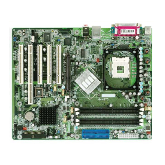
Hardware Installation Chapter 2 - Hardware Installation System Board Layout G4H875-N... - Page 17 Hardware Installation G4H875-C...
-
Page 18: Hardware Installation
PCI Slot 4 Protect (SW1) PWR-LED ATX-SW 1st AC power-on Front audio (JP11) S/PDIF Diagnostic LED 1 LED 4 LEDs LED 2 LED 5 HD-LED RESET SPEAKER G4H875-B Note: The illustrations on the following pages are based on the G4H875-N system board. -
Page 19: System Memory
Hardware Installation Warning: Electrostatic discharge (ESD) can damage your system board, processor, disk drives, add-in boards, and other components. Perform the upgrade instruction procedures described at an ESD workstation only. If such a station is not available, you can provide some ESD protection by wearing an antistatic wrist strap and attaching it to a metal part of the system chassis. - Page 20 Hardware Installation The system board supports the following memory interface. Single Channel (SC) Data will be accessed in chunks of 64 bits (8B) from the memory channels. Virtual Single Channel (VSC) If both channels are populated with different memory configurations, the MCH defaults to Virtual Single Channel.
- Page 21 Hardware Installation BIOS Setting Configure the system memory in the Advanced Chipset Features submenu of the BIOS. The table below lists the various optimal operating modes that should be configured for the memory channel operation. Channel 0 Channel 1 Config DDR 1 DDR 2 DDR 1...
- Page 22 Hardware Installation Channel 0 Channel 1 DDR 1 DDR 2 DDR 1 DDR 2 Config P(*)(2,4) Dynamic Mode Addressing P(*)(2,4) P(*)(1,3) P(*)(1,3) Dynamic Mode Addressing P(*)(1,3) P(*)(2,4) P(*)(1,3) P(*)(2,4) Dynamic Mode Addressing P(*)(2,4) P(*)(2,4) Dynamic Mode Addressing P(*)(1,3) P(*)(1,3) Dynamic Mode Addressing P(*)(1,3) P(*)(2,4) P(*)(1,3)
-
Page 23: Installing The Dim Module
Hardware Installation Installing the DIM Module A DIM module simply snaps into a DIMM socket on the system board. Pin 1 of the DIM module must correspond with Pin 1 of the socket. Notch Pin 1 1. Pull the “tabs” which are at the ends of the socket to the side. 2. -
Page 24: Cpu
Hardware Installation Overview The system board is equipped with a surface mount 478-pin CPU socket. This socket is exclusively designed for installing an Intel processor. Installing the CPU 1. Locate Socket 478 on the system board. 2. Unlock the socket by pushing the lever sideways, away from the socket, then lifting it up to a 90 angle. - Page 25 Hardware Installation 3. Position the CPU above the socket then align the gold mark on the corner of the CPU (designated as pin 1) with pin 1 of the socket. Important: Handle the CPU by its edges and avoid touching the pins. Gold mark Pin 1 4.
-
Page 26: Installing The Fan And Heat Sink
Hardware Installation 5. Once the CPU is in place, push down the lever to lock the socket. The lever should click on the side tab to indicate that the CPU is completely secured in the socket. Installing the Fan and Heat Sink The CPU must be kept cool by using a CPU fan with heatsink. - Page 27 Hardware Installation 1. The system board comes with the retention module base already installed. Retention Retention hole hole Retention Retention hole hole Retention module base 2. Position the fan / heat sink and retention mechanism assembly on the CPU, then align and snap the retention legs’ hooks to the retention holes at the 4 corners of the retention module base.
- Page 28 Hardware Installation 3. The retention levers at this time remains unlocked as shown in the illustration below. Retention lever Retention lever 4. Move the retention levers to their opposite directions then push them down. This will secure the fan / heat sink and retention mechanism assembly to the retention module base.
-
Page 29: Jumper Settings
Hardware Installation Jumper Settings Clear CMOS Data 1-2 On: Normal 2-3 On: (default) Clear CMOS Data If you encounter the following, a) CMOS data becomes corrupted. b) You forgot the supervisor or user password. c) You are unable to boot-up the computer system because the processor’s ratio/clock was incorrectly set in the BIOS. - Page 30 Hardware Installation 4. After powering-on the system, press <Del> to enter the main menu of the BIOS. 5. Select the Frequency/Voltage Control submenu and press <En- ter>. 6. Set the processor’s ratio/clock to its default setting or an appropriate bus clock or frequency ratio. Refer to the Frequency/ Voltage Control section in chapter 3 for more information.
- Page 31 Hardware Installation PS/2 Power Select 1-2 On: VCC 2-3 On: 5VSB (default) JP2 is used to select the power of the PS/2 keyboard or PS/2 mouse port. Selecting 5VSB will allow you to use the PS/2 keyboard or PS/2 mouse to wake up the system. BIOS Setting Configure the PS/2 keyboard/mouse wake up function in the Inte- grated Peripherals submenu of the BIOS.
-
Page 32: Usb Power Select
Hardware Installation USB Power Select 1-2 On: VCC 2-3 On: 5VSB (default) JP3 is used to select the power of the USB ports. Selecting 5VSB will allow you to use the USB keyboard to wake up the system. BIOS Setting “USB KB WakeUp From S3(S4)”... - Page 33 Hardware Installation Power-on Select 2-3 On: 1-2 On: Power-on via Power-on via AC power power button (default) JP6 is used to select the method of powering on the system. If you want the system to power-on once AC power comes in, set JP6 pins 2 and 3 to On.
- Page 34 Hardware Installation 1st AC Power-on On: Auto power-on only on 1st AC in Off: Power-on via JP11 power button (default) JP11 is used to select the method of powering on the system. Set JP11 to On if you want the system to automatically power-on only the first time AC power comes in.
- Page 35 Hardware Installation BIOS Write Protect “White” represents the switch’s position. 1-2 On: 1-2 Off: BIOS Write BIOS Not Write Protected Protected SW1 is used to configure the BIOS Write Protect function. When this function is enabled, the system will be protected from unneces- sary updating or flashing of the BIOS.
-
Page 36: Rear Panel I/O Ports
Rear Panel I/O Ports LAN 2 LAN 1 PS/2 Mouse Parallel Mic-in Line-in Line-out PS/2 COM 1 COM 2 USB 3-4 USB 1-2 G4H875-N PS/2 Parallel Mouse Mic-in USB 4 Line-in Line-out PS/2 COM 1 COM 2 USB 3 USB 1-2 G4H875-C... - Page 37 Hardware Installation PS/2 Mouse and PS/2 Keyboard Ports PS/2 Mouse PS/2 Keyboard The system board is equipped with an onboard PS/2 mouse (Green) and PS/2 keyboard (Purple) ports - both at location CN1 of the system board. The PS/2 mouse port uses IRQ12. If a mouse is not connected to this port, the system will reserve IRQ12 for other expansion cards.
-
Page 38: Serial Ports
COM 4 COM 3 G4H875-N/C only G4H875-N and G4H875-C are equipped with 2 onboard serial ports (COM 1: CN3 and COM 2: CN4) - both in Teal/Turquoise color. It is also equipped with two 9-pin connectors (COM 4: J14 and COM 3: J16) for connecting external serial ports. -
Page 39: Parallel Port
Hardware Installation Parallel Port Parallel The system board has a standard parallel por t (Burgundy) at location CN7 for interfacing your PC to a parallel printer. It sup- ports SPP, ECP and EPP. Setting Function Allows normal speed operation but (Standard Parallel Port) in one direction only. -
Page 40: Universal Serial Bus Ports
Plug and Play peripherals. G4H875-N and G4H875-C are each equipped with four onboard USB 2.0/1.1 ports (Black) are at locations CN5 (USB 3-4) and CN6 (USB 1-2) of the system board. - Page 41 Hardware Installation Wake-On-USB Keyboard The Wake-On-USB Keyboard function allows you to use a USB keyboard to wake up a system from the S3 (STR - Suspend To RAM) state. To use this function: • Jumper Setting: JP3 must be set to “2-3 On: 5VSB”. Refer to “USB Power Select” in this chapter for more information.
- Page 42 G4H875-N only LAN 1 G4H875-N is equipped with 2 onboard RJ45 LAN ports. LAN 1 which is controlled by the Intel 82551QM chip is at location CN6 and LAN 2 which is controlled by the Intel Gigabit 82547EI chip is at location CN5.
- Page 43 Hardware Installation Audio Mic-in Line-in Line-out Front audio Mic-in, Line-in and Line-out The mic-in, line-in and line-out jacks are at location CN2 of the system board. A jack is a one-hole connecting interface for insert- ing a plug. • Mic-in Jack (Pink) This jack is used to connect an external microphone.
- Page 44 Hardware Installation Front Audio The front audio connector (J3) allows you to connect to the line-out and mic-in jacks that are at the front panel of your sys- tem. Using this connector will disable the rear audio’s line-out and mic-in functions. Remove the jumper caps from pins 5-6 and pins 9-10 of J3 prior to connecting the front audio cable connector.
-
Page 45: I/O Connectors
Hardware Installation I/O Connectors Game/MIDI Port The system board is equipped with a 15-pin connector at loca- tion J2 for connecting an external game/MIDI port. The game/ MIDI port may be mounted on a card-edge bracket. Install the card-edge bracket to the system chassis then connect the game/ MIDI port cable to connector J2. -
Page 46: Internal Audio Connectors
Hardware Installation Internal Audio Connectors Ground Ground Ground Ground Left audio Right audio Left audio Right audio channel channel channel channel CD-in AUX-in The CD-in (J1) and AUX-in (J4) connectors are used to receive audio from a CD-ROM drive, TV tuner or MPEG card. - Page 47 Hardware Installation S/PDIF Connector SPDIF out SPDIF in The S/PDIF connector (J5) is used to connect external S/PDIF ports. The S/PDIF ports may be mounted on a card-edge bracket. Install the card-edge bracket to the system chassis then connect the audio cable connector to J5. Make sure pin 1 of the audio cable connector is aligned with pin 1 of J5.
-
Page 48: Floppy Disk Drive Connector
Hardware Installation Floppy Disk Drive Connector The system board is equipped with a shrouded floppy disk drive connector for connecting a standard floppy disk drive. To prevent improper floppy cable installation, the shrouded floppy disk header has a keying mechanism. The 34-pin connector on the floppy cable can be placed into the header only if pin 1 of the connector is aligned with pin 1 of the header. -
Page 49: Serial Ata Connectors
Hardware Installation Serial ATA Connectors SATA 2 SATA 1 The system board is equipped with two Serial ATA connectors for connecting Serial ATA devices. Connect one end of the Serial ATA cable to J22 (SATA 2) or J23 (SATA 1) and the other end to your Serial ATA device. - Page 50 Hardware Installation 5. Install the Intel RAID driver. For steps 1 to 4, refer to chapter 3 for more information. For step 5, refer to chapter 4 for more information.
-
Page 51: Ide Disk Drive Connector
Hardware Installation IDE Disk Drive Connector IDE 1 IDE 2 IDE 2 IDE 1 The system board is equipped with two shrouded PCI IDE headers that will interface four Enhanced IDE (Integrated Drive Electronics) disk drives. To prevent improper IDE cable installation, each shrouded PCI IDE header has a keying mechanism. - Page 52 Hardware Installation Note: Refer to your disk drive user’s manual for information about selecting proper drive switch settings. Adding a Second IDE Disk Drive When using two IDE drives, one must be set as the master and the other as the slave. Follow the instructions provided by the drive manufacturer for setting the jumpers and/or switches on the drives.
-
Page 53: Irda Connector
Hardware Installation IrDA Connector IRRX N. C. Ground IRTX Connect your IrDA cable to connector J7 on the system board. Note: The sequence of the pin functions on some IrDA cable may be reversed from the pin function defined on the system board. Make sure to connect the cable to the IrDA connector according to their pin functions. -
Page 54: Cooling Fan Connectors
Hardware Installation Cooling Fan Connectors Ground Ground Power Power N. C. Sense 2nd fan CPU fan Power Ground Sense NB fan Ground Power Sense Chassis fan Connect the CPU fan’s cable connector to the CPU fan connec- tor (J13) on the system board. Connect the Intel 875P fan’s cable connector to the NB fan connector (J27) on the system board. - Page 55 Hardware Installation Wake-On-LAN Connector Ground +5VSB Your LAN card package should include a cable. Connect one end of the cable to the wakeup header on the card and the other end to location J10 on the system board. The network will detect Magic Packet and assert a wake up signal to power-up the system.
- Page 56 Hardware Installation Chassis Open Connector Chassis signal Ground The system board supports the chassis intrusion detection func- tion. To use this function, connect the chassis intrusion sensor cable from the chassis to J6. Whenever a chassis component has been removed, the sensor sends signal to J6 alerting you of a chassis intrusion event.
- Page 57 Hardware Installation LEDs DIMM Standby Power LED PCI Standby Power LED LED 1 LED 4 LED 2 LED 5 Diagnostic LEDs DIMM Standby Power LED This LED will turn red when the system’s power is on or when it is in the Suspend state (Power On Suspend or Suspend to RAM). It will not light when the system is in the Soft-Off state.
- Page 58 Hardware Installation LED 2 LED 4 LED 5 LED 1 Early program chipset reg- ister before POST. Testing memory presence. Detecting memory size. No memory present. Programming DRAM tim- ing register. Calculating DRAM size variable including row, col- umn and bank. Initializing JEDEC of cur- rent DRAM row.
-
Page 59: Power Connectors
Hardware Installation Power Connectors 3.3V 3.3V -12V 3.3V Ground Ground PS-ON Ground Ground Ground Ground Ground PW-OK 5VSB +12V +12V +12V Ground Ground We recommend that you use a power supply that complies with the ATX12V Power Supply Design Guide Version 1.1. An ATX12V power supply has a standard 20-pin ATX main power connector and a 4-pin +12V power connector that must be inserted onto CN9 and CN8 connectors respectively. -
Page 60: Front Panel Connectors
Hardware Installation Front Panel Connectors ATX-SW PWR-LED HD-LED SPEAKER RESET HD-LED: Primary/Secondary IDE LED This LED will light when the hard drive is being accessed. RESET: Reset Switch This switch allows you to reboot without having to power off the system thus prolonging the life of the power supply or system. - Page 61 Hardware Installation PWR-LED: Power/Standby LED When the system’s power is on, this LED will light. When the system is in the S1 (POS - Power On Suspend) state, it will blink every second. When the system is in the S3 (STR - Suspend To RAM) state, it will blink every second.
-
Page 62: Chapter 3 - Bios Setup
BIOS Setup Chapter 3 - BIOS Setup Award BIOS Setup Utility The Basic Input/Output System (BIOS) is a program that takes care of the basic level of communication between the processor and peripherals. In addition, the BIOS also contains codes for various advanced features found in this system board. -
Page 63: Bios Setup
BIOS Setup Standard CMOS Features Use the arrow keys to highlight “Standard CMOS Features” and press <Enter>. A screen similar to the one below will appear. The settings on the screen are for reference only. Your version may not be identical to this one. - Page 64 BIOS Setup IDE Channel 0 Master, IDE Channel 0 Slave, IDE Channel 1 Master and IDE Channel 1 Slave Move the cursor to the “IDE Channel 0 Master”, “IDE Channel 0 Slave”, “IDE Channel 1 Master” or “IDE Channel 1 Slave” field, then press <Enter>.
- Page 65 BIOS Setup Capacity Displays the approximate capacity of the disk drive. Usually the size is slightly greater than the size of a formatted disk given by a disk checking program. Cylinder This field displays the number of cylinders. Head This field displays the number of read/write heads. Precomp This field displays the number of cylinders at which to change the write timing.
- Page 66 BIOS Setup Video This field selects the type of video adapter used for the primary system monitor. Although secondary monitors are supported, you do not have to select the type. The default setting is EGA/VGA. EGA/VGA Enhanced Graphics Adapter/Video Graphics Array. For EGA, VGA, SVGA and PGA monitor adapters.
- Page 67 BIOS Setup Extended Memory Displays the amount of extended memory detected during boot-up. Total Memory Displays the total memory available in the system.
-
Page 68: Advanced Bios Features
BIOS Setup Advanced BIOS Features The Advanced BIOS Features allows you to configure your system for basic operation. Some entries are defaults required by the system board, while others, if enabled, will improve the performance of your system or let you set some features according to your preference. The screen above list all the fields available in the Advanced BIOS Features submenu, for ease of reference in this manual. - Page 69 BIOS Setup CPU Feature Move the cursor to this field and press <Enter>. The following screen will appear. The settings on the screen are for reference only. Your version may not be identical to this one. Delay Prior To Thermal This field is used to select the time that would force the CPU to a 50% duty cycle when it exceeds its maximum operating temperature therefore protecting the CPU and the system board from...
- Page 70 BIOS Setup Limit CPUID MaxVal The CPUID instruction of some newer CPUs will return a value greater than 3. The default is Disabled because this problem does not exist in the Windows series operating systems. If you are using an operating system other than Windows, this problem may occur. To avoid this problem, enable this field to limit the return value to 3 or lesser than 3.
- Page 71 BIOS Setup ® ® Hyper-Threading Technology (for Intel Pentium 4 Processor with Hyper-Threading Technology only) ® ® This field is used to enable the functionality of the Intel Pentium Processor with Hyper-Threading Technology and will appear only when using this processor. Quick Power On Self Test This field speeds up Power On Self Test (POST) whenever the system is powered on.
- Page 72 BIOS Setup Gate A20 Option This entry allows you to select how gate A20 is handled. Gate A20 is a device used to address memory above 1 Mbyte. Initially, gate A20 was handled via the keyboard controller. Today, while keyboards still provide this support, it is more common, and much faster, for the system chipset to provide support for gate A20.
- Page 73 BIOS Setup Security Option This field determines when the system will prompt for the password - everytime the system boots or only when you enter the BIOS setup. Set the password in the Set Supervisor/User Password submenu. System The system will not boot and access to Setup will be denied unless the correct password is entered at the prompt.
-
Page 74: Advanced Chipset Features
BIOS Setup Advanced Chipset Features The settings on the screen are for reference only. Your version may not be identical to this one. This section gives you functions to configure the system based on the specific features of the chipset. The chipset manages bus speeds and access to system memory resources. - Page 75 BIOS Setup Manual If you want your system to run at a performance better than the one “by SPD”, select “Manual” then select the best option in the “CAS Latency Time” to “DRAM RAS# Precharge” fields. CAS Latency Time This field is used to select the local memory clock periods. Active to Precharge Delay The options are 5, 6, 7 and 8.
- Page 76 BIOS Setup System BIOS Cacheable When this field is enabled, accesses to the system BIOS ROM addressed at F0000H-FFFFFH are cached, provided that the cache controller is enabled. The larger the range of the Cache RAM, the higher the efficiency of the system. Video BIOS Cacheable As with caching the system BIOS, enabling the Video BIOS cache will allow access to video BIOS addresssed at C0000H to C7FFFH to...
- Page 77 BIOS Setup DRAM Data Integrity Mode The ECC (Error Checking and Correction) function is supported only in x72 (72-bit) PC SDRAM DIMMs. If you are using x64 (64-bit) PC SDRAM DIMMs, set this field to Non-ECC. Non-ECC Uses x64 PC SDRAM DIMM. This option allows the system to recover from memory failure.
-
Page 78: Integrated Peripherals
BIOS Setup Integrated Peripherals The settings on the screen are for reference only. Your version may not be identical to this one. OnChip IDE Device Move the cursor to this field and press <Enter>. The following screen will appear. The settings on the screen are for reference only. Your version may not be identical to this one. - Page 79 BIOS Setup IDE HDD Block Mode Enabled The IDE HDD uses the block mode. The system BIOS will check the hard disk drive for the maximum block size the system can transfer. The block size will depend on the type of hard disk drive. Disabled The IDE HDD uses the standard mode.
- Page 80 BIOS Setup IDE Primary Master/Slave UDMA and IDE Secondary Master UDMA These fields allow you to set the Ultra DMA in use. When Auto is selected, the BIOS will select the best available option after checking your hard drive or CD-ROM. Auto The BIOS will automatically detect the settings for you.
- Page 81 BIOS Setup Serial ATA Port0 Mode and Serial ATA Port1 Mode These fields are used to select the master/slave mode of the Serial ATA drives. Make sure they do not conflict with the set- tings of the IDE hard drives. Onboard Device Move the cursor to this field and press <Enter>.
- Page 82 BIOS Setup AC97 Audio Auto Select this option when using the onboard AC97 codec. Disabled Select this option when using a PCI sound card. 6300ESB WDT Function This field is used to enable or disable the Watchdog timer function. WDT Timer Value This field is used to select the time interval of the Watchdog timer.
- Page 83 BIOS Setup Hot Key When this option is selected, select the function key you would like to use to power-on the system in the “Hot Key Power On” field. Mouse Left When this option is selected, double-click the left button of the mouse to power-on the system. Mouse Right When this option is selected, double-click the right button of the mouse to power-on the system.
- Page 84 BIOS Setup UART Mode Select This field is used to select the type of IrDA standard supported by your IrDA device. For better transmission of data, your IrDA peripheral device must be within a 30 angle and within a distance of 1 meter.
- Page 85 BIOS Setup “EPP (Enhanced Parallel Port)” Allows bidirectional parallel port operation at maximum speed. If you selected EPP, the “EPP Mode Select” field is selectable. If you selected ECP, the “ECP Mode Use DMA” field is selectable. If you selected ECP+EPP, both “EPP Mode Select” and “ECP Mode Use DMA”...
- Page 86 Onboard Serial Port 3 (G4H875-N and G4H875-C only) This field is used to select the serial port 3’s I/O address. Onboard Serial Port 3 IRQ (G4H875-N and G4H875-C only) This field is used to select the serial port 3’s IRQ address.
-
Page 87: Power Management Setup
BIOS Setup Power Management Setup The Power Management Setup allows you to configure your system to most effectively save energy. The screen above list all the fields available in the Power Management Setup submenu, for ease of reference in this manual. In the actual CMOS setup, you have to use the scroll bar to view the fields. - Page 88 BIOS Setup Run VGABIOS if S3 Resume When this field is set to Auto, the system will initialize the VGA BIOS when it wakes up from the S3 state. This can be configured only if the “ACPI Suspend Type” field is set to “S3(STR)”. Power Management This field allows you to select the type (or degree) of power saving by changing the length of idle time that elapses before the Suspend...
- Page 89 BIOS Setup MODEM Use IRQ This field is used to set an IRQ channel for the modem installed in your system. Suspend Mode This is selectable only when the Power Management field is set to User Define. When the system enters the Suspend mode according to the power saving time selected, the CPU and onboard peripherals will be shut off.
- Page 90 BIOS Setup Wake-Up by PCI Card Enabled This field should be set to Enabled only if your PCI card such as LAN card or modem card uses the PCI PME (Power Management Event) signal to remotely wake up the system. Access to the LAN card or PCI card will cause the system to wake up.
- Page 91 BIOS Setup Resume By Alarm Enabled When Enabled, you can set the date and time you would like the Soft Power Down (Soft-Off) PC to power-on in the “Date (of Month) Alarm” and “Time (hh:mm:ss) Alarm” fields. However, if the system is being accessed by incoming calls or the network (Resume On Ring/LAN) prior to the date and time set in these fields, the system will give priority to the incoming calls...
- Page 92 BIOS Setup PnP/PCI Configurations This section describes configuring the PCI bus system. It covers some very technical items and it is strongly recommended that only experienced users should make any changes to the default settings. The settings on the screen are for reference only. Your version may not be identical to this one.
- Page 93 BIOS Setup IRQ Resources Move the cursor to this field and press <Enter>. The “IRQ-3” to “IRQ-15” fields will appear. Set each system interrupt to either PCI Device or Reserved. The settings on the screen are for reference only. Your version may not be identical to this one.
-
Page 94: Pc Health Status
BIOS Setup PC Health Status The settings on the screen are for reference only. Your version may not be identical to this one. Shutdown Temperature You can prevent the system from overheating by selecting a tem- perature in this field. If the system detected that its temperature exceeded the one set in this field, it will automatically shutdown. - Page 95 BIOS Setup VCC3(V), +12(V), -12(V), VCC(V), VBAT(V) and 5VSB(V) These fields show the output voltage of the power supply. Note: The onboard hardware monitor function is capable of detecting “system health” conditions but if you want a warning message to pop-up or a warning alarm to sound when an abnormal condition occurs, you must install the Winbond Hardware Doctor utility.
- Page 96 BIOS Setup Frequency/Voltage Control The settings on the screen are for reference only. Your version may not be identical to this one. CPU Clock Ratio This field is used to select the CPU’s frequency ratio. Important: The frequency ratio of some processors may have been locked by the manufacturer.
- Page 97 BIOS Setup CPU Clock This field provides several options for selecting the external system bus clock of the processor. The available options allow you to adjust the processor’s bus clock by 1MHz increment. Important: Selecting an external bus clock other than the default setting may result to the processor’s or system’s instability and are not guaranteed to provide better system performance.
- Page 98 BIOS Setup Load Fail-Safe Defaults The “Load Fail-Safe Defaults” option loads the troubleshooting default values permanently stored in the ROM chips. These settings are not optimal and turn off all high performance features. You should use these values only if you have hardware problems. Highlight this option in the main menu and press <Enter>.
-
Page 99: Load Optimized Defaults
BIOS Setup Load Optimized Defaults The “Load Optimized Defaults” option loads optimized settings from the BIOS ROM. Use the default values as standard values for your system. Highlight this option in the main menu and press <Enter>. Type <Y> and press <Enter> to load the Setup default values. -
Page 100: Set Supervisor Password
BIOS Setup Set Supervisor Password If you want to protect your system and setup from unauthorized entry, set a supervisor’s password with the “System” option selected in the Advanced BIOS Features. If you want to protect access to setup only, but not your system, set a supervisor’s password with the “Setup”... -
Page 101: Set User Password
BIOS Setup Set User Password If you want another user to have access only to your system but not to setup, set a user’s password with the “System” option se- lected in the Advanced BIOS Features. If you want a user to enter a password when trying to access setup, set a user’s password with the “Setup”... - Page 102 BIOS Setup Save & Exit Setup When all the changes have been made, highlight “Save & Exit Setup” and press <Enter>. Type “Y” and press <Enter>. The modifications you have made will be written into the CMOS memory, and the system will reboot. You will once again see the initial diagnostics on the screen.
-
Page 103: Exit Without Saving
BIOS Setup Exit Without Saving When you do not want to save the changes you have made, highlight “Exit Without Saving” and press <Enter>. Type “Y” and press <Enter>. The system will reboot and you will once again see the initial diagnostics on the screen. If you wish to make any changes to the setup, press <Ctrl>... -
Page 104: Updating The Bios
BIOS Setup Updating the BIOS To update the BIOS, you will need the new BIOS file and a flash utility, AWDFLASH.EXE. Please contact technical support or your sales representative for the files. Note: AWDFLASH.EXE works only in DOS mode. 1. Save the new BIOS file along with the flash utility AWDFLASH.EXE to a floppy disk. - Page 105 BIOS Setup 6. The following will appear. Do You Want to Save BIOS (Y/N) This question refers to the current existing BIOS in your system. We recommend that you save the current BIOS and its flash utility; just in case you need to reinstall the BIOS. To save the current BIOS, press <Y>...
-
Page 106: Chapter 4 - Supported Softwares
Supported Software Chapter 4 - Supported Software Drivers, Utilities and Software Applications The CD that came with the system board contains drivers, utilities and software applications required to enhance the performance of the system board. Insert the CD into a CD-ROM drive. The autorun screen (Main Board Utility CD) will appear. -
Page 107: Supported Software
Supported Software Intel 875 INF Update Utility The Intel 875 INF Update Utility is used for updating Windows's INF files so that the Intel chipset can be recognized and configured properly in the system. To install the utility, please follow the steps below. 1. -
Page 108: Installation Notes
Supported Software Intel 10/100/1000 LAN Drivers To install the driver, please follow the steps below. 1. Click “Intel 10/100/1000 LAN Drivers” on the main menu. 2. Click “Wired LAN Adapters”. The following screen will appear. 3. Click “Install Software”. This will install the LAN application software. - Page 109 Supported Software Realtek ALC202A Audio Drivers To install the driver, please follow the steps below. 1. Click “Realtek ALC202A Audio Drivers”. The following screen will appear. 2. Follow the prompts on the screen to complete installation. 3. Reboot the system for the driver to take effect.
- Page 110 Supported Software Microsoft DirectX V9.0C To install, please follow the steps below. 1. Click “Microsoft DirectX V9.0C” on the main menu. The following screen will appear. 2. Click “I accept the agreement” then click “Next”. 3. Follow the prompts on the screen to complete installation. 4.
- Page 111 Supported Software Winbond Hardware Doctor Winbond Hardware Doctor is capable of monitoring the system’s hardware conditions such as the temperature of the CPU and system, voltage, and speed of the cooling fans. It also allows you to manually set a range to the items being monitored. If the values are over or under the set range, a warning message will pop-up.
- Page 112 Supported Software RAID Configuration and 6300ESB RAID Drivers The following describes the steps on configuring RAID. 1. Set the “On-Chip Serial ATA” field to “Enhanced Mode”. (Inte- grated Peripherals submenu - OnChip IDE Device” section of the Award BIOS.) 2. Set the “SATA Mode” field to “RAID”. (Integrated Peripherals submenu - OnChip IDE Device”...
- Page 113 Supported Software ® 5. Select “Intel 6300ESB SATA RAID Controller” from the list then press <Enter>. 6. The next screen should confirm that you have selected the Intel(r) RAID controller. Press <Enter> again to continue. 7. Finish the Windows installation. Leave the floppy disk in the floppy drive until the system reboots itself.
- Page 114 Supported Software Rebuilding a RAID Array Rebuilding is used to reconstruct an existing RAID array. It is the process of recovering data by copying all data from one hard drive to another. Data is then synchronized between the two hard drives. 1.
- Page 115 Supported Software 3. Run the Intel Storage Utility screen. It will show that the status of RAID Volume 1 is “Degraded” and the damaged hard drive is a “Missing Hard Drive”. 4. To rebuild the RAID array, you must first install a new hard drive. The newly installed hard drive will appear under the “Non-RAID Hard Drives”...
- Page 116 Supported Software 5. Click the right button of your mouse on the new hard drive. “Rebuild to this Disk” will appear. Click to select the rebuild function. 6. Select the hard drive you want to use to rebuild the RAID 1 volume then click “Next”.
- Page 117 Supported Software 7. The hard drive you have selected will appear in the “RAID Hard Drives” section with the rebuilding status of RAID Volume 1 shown on the screen.
- Page 118 Supported Software Intel USB 2.0 Drivers ® ® The USB 2.0 driver supports Windows 98SE, Windows ME and ® Windows 2000. To install, go directly to the USB20\WIN9X directory of the CD then click SETUP.EXE. ® Windows ® If your Windows XP CD already includes Service Pack 1, the USB 2.0 driver will automatically install when you install the operating system.
-
Page 119: Appendix A - Enabling Hyper-Threading Technology
Enabling Hyper-Threading Technology Appendix A - Enabling Hyper-Threading Technology Enabling Hyper-Threading Technology To enable the functionality of the Hyper-Threading Technology, please follow the requirements and steps below. Basically, the following ® ® presumes that you have already installed an Intel Pentium Processor with Hyper-Threading Technology. - Page 120 Enabling Hyper-Threading Technology Click the General tab. The processor shown under Computer should resemble the one shown below. Now click the Hardware tab then click Device Manager. The items shown under Computer and Processors should resemble the ones shown below.
- Page 121 Enabling Hyper-Threading Technology Lastly, press the <Ctr l> <Alt> and <Del> keys simultaneously. The Windows Task Manager dialog box will appear. Click the Performance tab. The diagram under CPU Usage History should resemble the one shown below.
-
Page 122: Appendix B - System Error Messages
System Error Message Appendix B - System Error Message When the BIOS encounters an error that requires the user to correct something, either a beep code will sound or a message will be displayed in a box in the middle of the screen and the message, PRESS F1 TO CONTINUE, CTRL-ALT-ESC or DEL TO ENTER SETUP, will be shown in the information box at the bottom. - Page 123 System Error Message setting than indicated in Setup. Determine which setting is correct, either turn off the system and change the jumper or enter Setup and change the VIDEO selection. FLOPPY DISK(S) fail (80) Unable to reset floppy subsystem. FLOPPY DISK(S) fail (40) Floppy type mismatch.
-
Page 124: Appendix C - Troubleshooting
Troubleshooting Appendix C - Troubleshooting Troubleshooting Checklist This chapter of the manual is designed to help you with problems that you may encounter with your personal computer. To efficiently troubleshoot your system, treat each problem individually. This is to ensure an accurate diagnosis of the problem in case a problem has multiple causes. -
Page 125: Power Supply
Troubleshooting The picture seems to be constantly moving. 1. The monitor has lost its vertical sync. Adjust the monitor’s vertical sync. 2. Move away any objects, such as another monitor or fan, that may be creating a magnetic field around the display. 3. -
Page 126: Hard Drive
Troubleshooting Hard Drive Hard disk failure. 1. Make sure the correct drive type for the hard disk drive has been entered in the BIOS. 2. If the system is configured with two hard drives, make sure the bootable (first) hard drive is configured as Master and the second hard drive is configured as Slave. -
Page 127: Serial Port
Troubleshooting Serial Port The serial device (modem, printer) doesn’t output anything or is outputting garbled characters. 1. Make sure that the serial device’s power is turned on and that the device is on-line. 2. Verify that the device is plugged into the correct serial port on the rear of the computer. -
Page 128: Appendix D - Watchdog Sample Code
Watchdog Timer Appendix D - Watchdog Timer To use the Watchdog timer function, please follow the steps below. 1. Set the "6300ESB WDT Function" field to Enabled (Integrated Peripherals submenu, Onboard Device section of the BIOS). 2. Set the time interval of the Watchdog timer in the "WDT Timer Value"... -
Page 129: Watchdog Timer
Watchdog Timer eax,8000ec68h ;Select Bus0 Dev1D Func4 Reg68 dx,eax $ +2 dx,0cfch al,02h dx,al ;Reg 68 = 2 - Enable WDT $ +2 ah,4ch ;End Program ;Main end ;___________________________________________________________ PCI Function Address 33222222 22221111 11111100 00000000 10987654 32109876 54321098 76543210 ;____________________________________________________________ 1XXXXXXX BBBBBBBB DDDDDFFF RRRRRR00 ;...