Table of Contents
Advertisement
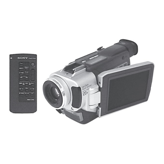
DCR-TRV15E/TRV17E
SERVICE MANUAL
SERVICE MANUAL
Ver 1.1 2001. 07
Level 2
On the VC-260 board
This service manual provides the information that is premised the
circuit board replacement service and not intended repair inside the
VC-260 board.
Therefore, schematic diagram, printed wiring board, waveforms, parts
location and electrical parts list of the VC-260 board are not shown.
The following pages are not shown.
Printed wiring board ......................... Pages 4-11 to 4-14
Schematic diagram .......................... Pages 4-15 to 4-50
Waveforms and parts location ......... Pages 4-93 to 4-96
Electrical parts list ............................ Pages 6-17 to 6-26
Video camera
recorder
System
Video recording system
2 rotary heads
Helical scanning system
Audio recording system
Rotary heads, PCM system
Quantization: 12 bits (Fs 32 kHz,
stereo 1, stereo 2), 16 bits
(Fs 48 kHz, stereo)
Video signal
PAL colour, CCIR standards
Usable cassette
Mini DV cassette with the
mark printed
Tape speed
SP: Approx. 18.81 mm/s
LP: Approx. 12.56 mm/s
Recording/playback time (using
cassette DVM60)
SP: 1 hour
LP: 1.5 hours
Fastforward/rewind time
(using cassette DVM60)
Approx. 2 min. and 30 seconds
Photo : DCR-TRV17E
RMT-814
SPECIFICATIONS
Viewfinder
Electric viewfinder (colour)
Image device
4.5 mm (1/4 type) CCD (Charge
Coupled Device)
Approx. 800 000 pixels
(Effective: Approx. 400 000
pixels)
Lens
Carl Zeiss
Combined power zoom lens
Filter diameter
30 mm (1 3/16 in.)
10× (Optical), 120× (Digital)
Focal length
3.3 - 33 mm (5/32 - 1 5/16 in.)
When converted to a 35 mm still
camera
Camera/Memory (DCR-TRV17E
only) mode:
42 - 420 mm (1 11/16 - 16 5/8 in.)
Colour temperature
Auto, HOLD (Hold),
Indoor
(3 200 K),
Outdoor (5 800 K)
DIGITAL VIDEO CAMERA RECORDER
Hong Kong Model
For MECHANISM ADJUSTMENTS, refer to the
"DV MECHANICAL ADJUSTMENT MANUAL
J MECHANISM " (9-929-807-11).
Minimum illumination
5 lx (lux) (F 1.7)
0 lx (lux) (in the NightShot
mode)*
* Objects unable to be seen due
to the dark can be shot with
infrared lighting.
Output connectors
S video output (AEP, UK model)
S video input/output
(E, HK, AUS, CN, JE model)
4-pin mini DIN
Luminance signal: 1 Vp-p, 75 Ω
(ohms), unbalanced
Chrominance signal: 0.3 Vp-p,
75 Ω (ohms)
Audio/Video output
(AEP, UK model)
Audio/Video input/output
(E, HK, AUS, CN, JE model)
AV MINI JACK, 1 Vp-p, 75 Ω
(ohms), unbalanced, sync
negative
327 mV, (at output impedance
more than 47 kΩ (kilohms))
RMT-814
AEP Model
UK Model
E Model
Australian Model
Chinese Model
Tourist Model
J MECHANISM
Output impedance with less than
2.2 kΩ (kilohms)/Stereo minijack
(ø 3.5mm)
DV output (AEP, UK model)
DV input/output
(E, HK, AUS, CN, JE model)
4-pin connector
Headphone jack
Stereo minijack (ø 3.5 mm)
USB jack (DCR-TRV17E only)
mini-B
LANC
jack
Special mini-minijack (ø 2.5 mm)
MIC jack
Stereo minijack (ø 3.5 mm)
— Continued on next page —
Advertisement
Table of Contents

Related Manuals for Sony DCR-TRV15E


Summary of Contents for Sony DCR-TRV15E
- Page 1 DCR-TRV15E/TRV17E RMT-814 SERVICE MANUAL SERVICE MANUAL AEP Model UK Model Ver 1.1 2001. 07 Level 2 E Model Hong Kong Model Australian Model Chinese Model Tourist Model Photo : DCR-TRV17E J MECHANISM RMT-814 On the VC-260 board For MECHANISM ADJUSTMENTS, refer to the “DV MECHANICAL ADJUSTMENT MANUAL...
- Page 2 Mass (approx.) Mass (approx.) 50.3 × 37.4 mm (2 × 1 1/2 in.) Flash memory 280 g (9.8 oz) DCR-TRV15E: 610 g (1 lb 5 oz) DCR-TRV17E: 4MB: MSA-4A DCR-TRV17E: 650 g (1 lb 6 oz) excluding mains lead 8.8 cm (3.5 type)
- Page 3 5 A/V connecting cable (1) DCR-TRV15E: JE/TRV17E: JE only 6 Shoulder strap (1) qd 2-pin conversion adaptor (1) 7 Lens cap (1) DCR-TRV15E: E, HK/TRV17E: E, HK only 8 “Memory Stick” (MSA-4A) (1) DCR-TRV17E only Table for difference of functions Model...
-
Page 4: Table Of Contents
Enlarging images recorded on tapes – Tape PB ZOOM ······ 1-17 BLOCK DIAGRAMS Quickly locating a scene using the zero set memory function ·· 1-18 3-1. OVERALL BLOCK DIAGRAM (1/4)(DCR-TRV15E) ·· 3-1 Searching the boundaries of recorded tape by title 3-2. OVERALL BLOCK DIAGRAM (1/4)(DCR-TRV17E) ·· 3-3 –... - Page 5 4-2. PRINTED WIRING BOARDS AND 4-4. MOUNTED PARTS LOCATION ································· 4-97 SCHEMATIC DIAGRAMS ············································ 4-8 ADJUSTMENTS • CD-303 (CCD IMAGER) PRINTED WIRING BOARD AND 1-1. Adjusting items when replacing main parts and boards ·· 5-2 SCHEMATIC DIAGRAM ······························ 4-9 5-1. CAMERA SECTION ADJUSTMENT ··························· 5-4 1-1.
- Page 6 2-3. TAPE PATH ADJUSTMENT ········································ 5-34 6-1-5. MAIN CHASSIS COMPLETE SECTION ····················· 6-5 Preparation for Adjustment ··········································· 5-34 6-1-6. EVF SECTION ································································ 6-6 Procedure after operations ············································· 5-34 6-1-7. OVERALL MECHANISM DECK SECTION (J100) ···· 6-7 5-3. VIDEO SECTION ADJUSTMENTS ··························· 5-35 6-1-8.
-
Page 7: Service Note
SERVICE NOTE POWER SUPPLY DURING REPAIRS In this unit, about 10 seconds after power is supplied to the battery terminal using the regulated power supply (8.4V), the power is shut off so that the unit cannot operate. This following two methods are available to prevent this. Take note of which to use during repairs. Method 1. -
Page 8: Self-Diagnosis Function
SELF-DIAGNOSIS FUNCTION SELF-DIAGNOSIS FUNCTION SELF-DIAGNOSIS DISPLAY When problems occur while the unit is operating, the self-diagnosis When problems occur while the unit is operating, the counter of the function starts working, and displays on the viewfinder, LCD screen viewfinder, LCD screen or LCD window consists of an alphabet or LCD window what to do. -
Page 9: Self-Diagnosis Code Table
SELF-DIAGNOSIS CODE TABLE Self-diagnosis Code Block Detailed Symptom/State Correction Function Code Non-standard battery is used. Use the info LITHIUM battery. Condensation. Remove the cassette, and insert it again after one hour. Video head is dirty. Clean with the optional cleaning cassette. LOAD direction. -
Page 10: General
DCR-TRV15E/TRV17E SECTION 1 This section is extracted from GENERAL instruction manual. (3-067-426-11) English Main Features Checking supplied accessories Taking moving or still images, and playing them back •Recording a picture (p. 28) Make sure that the following accessories are Убедитесь, что следующие принадлежности... -
Page 11: Getting Started
— Getting started — Using this manual Using this manual Note on Cassette Memory The instructions in this manual are for the two Инструкции в данном руководстве изложены Your camcorder is based on the DV format. You models listed in the table below. Before you start для... -
Page 12: Charging The Battery Pack
отличаться от цифр на Вашей видеокамере. window may differ from that on your camcorder. Step 1 Preparing the power Step 1 Preparing the power supply supply Recording time/ Playing time/ DCR-TRV15E DCR-TRV15E Recording with Recording with Playing time Playing time the viewfinder/ the LCD screen/... -
Page 13: Connecting To The Wall Socket
2, 3 совместимой электронной аппаратурой. SERIES Данный аппарат является совместимым с “InfoLITHIUM” is a trademark of Sony батарейным блоком “InfoLITHIUM” (серии М). Corporation. Ваша видеокамера работает только с We recommend charging the battery pack in an батарейным блоком “InfoLITHIUM”. -
Page 14: Step 3 Inserting A Cassette
Step 3 Inserting a cassette Step 3 Inserting a cassette (1) Install the power source. (1) Установите источник питания. Note (2) Slide OPEN/ EJECT in the direction of (2) Сдвиньте переключатель OPEN/ Do not press the cassette compartment down Не нажимайте кассетный отсек вниз с the arrow and open the lid. - Page 15 Recording a picture Recording a picture Recording data Adjusting the brightness of the The recording data (date/time or various settings Данные записи (дата/время или различные LCD screen установки, сделанные при записи) не when recorded) are not displayed while отображаются во время выполнения записи. recording.
-
Page 16: Shooting Backlit Subjects - Back Light
Recording a picture Recording a picture Indicators displayed in the Shooting backlit subjects recording mode – BACK LIGHT Индикаторы не записываются на ленту. The indicators are not recorded on tapes. When you shoot a subject with the light source Когда Вы снимаете объект с источником behind the subject or a subject with a light света... -
Page 17: Checking The Recording - End Search/Editsearch
Checking the recording Recording a picture – END SEARCH / EDITSEARCH / Rec Review Note The self-timer recording mode is automatically Режим записи по таймеру самозапуска You can use these buttons to check the recorded Вы можете использовать эти кнопки для cancelled when: автоматически... - Page 18 Playing back a tape Playing back a tape Date/time/ Various settings/ When monitoring on the LCD screen You can turn the LCD panel over and move it Вы можете перевернуть панель ЖКД и back to the camcorder body with the LCD screen придвинуть...
-
Page 19: Viewing The Recording On Tv
– while the digital effect function is set or in use функции фейдера when it is not needed. передачи сигналов, если она не требуется. – во время установки или использования is a trademark of Sony Corporation. является фирменным знаком корпорации Sony. функции цифрового эффекта 1-10... -
Page 20: Adjusting The White Balance Manually
Recording a still image on a tape Recording a still image on a tape – Tape Photo recording – Tape Photo recording If you record a moving subject with the tape Self-timer recording photo recording function When you play back the still picture on other Если... -
Page 21: Using The Wide Mode
Adjusting the white balance Using the wide mode manually In the automatic white balance mode You can record a 16:9 wide picture to watch on Вы можете записывать широкоформатное Point your camcorder at a white subject for about Направьте Вашу видеокамеру на белый the 16:9 wide-screen TV (16:9WIDE). -
Page 22: Using Special Effects - Picture Effect
Using special effects Using the fader function – Picture effect While using the bounce function, you cannot use the following functions: You can digitally process images to obtain special Вы можете выполнить цифровую обработку – Exposure изображений для получения спциальных effects like those in films or on TV. -
Page 23: Using The Program Ae Function
Using the PROGRAM Using special effects AE function – Digital effect You can select PROGRAM AE (Auto Exposure) Вы можете выбрать режим PROGRAM AE Notes mode to suit your specific shooting requirements. (автоматической экспозиции), который •The following functions do not work during •... -
Page 24: Adjusting The Exposure Manually
Adjusting the exposure manually Focusing manually You can manually adjust and set the exposure. Вы можете вручную отрегулировать и You can gain better results by manually adjusting Вы можете получить лучшие результаты Adjust the exposure manually in the following установить экспозицию. the focus in the following cases: путем... -
Page 25: Frame By Frame Recording - Cut Recording
Interval recording Interval recording To cancel the interval recording •Set INT. REC to OFF in the menu settings. • Установите пункт INT. REC в положение •Set the POWER switch to OFF (CHG), PLAYER OFF в установках меню. or MEMORY (DCR-TRV17E only). •... -
Page 26: Advanced Playback Operations
Playing back a tape — Advanced Playback Operations — Playing back a tape with digital effects with picture effects During playback, you can process a scene using Во время воспроизведения Вы можете the digital effect functions: STILL, FLASH, LUMI. обработать эпизода с использованием During playback, you can process a scene using Во... -
Page 27: Quickly Locating A Scene Using The Zero Set Memory Function
Quickly locating a Searching the boundaries scene using the zero of recorded tape by title set memory function – Title search Ваша видеокамера осуществляет продвижение Your camcorder goes forward or backward to If you use a tape with cassette memory, Если... -
Page 28: Searching For A Photo - Photo Search/Photo Scan
Searching a recording by date Searching for a photo – Date search – Photo search/Photo scan Note If one day’s recording is less than two minutes, Если однодневная запись продолжалась Вы можете выполинть поиск неподвжиного You can search for a still picture you have your camcorder may not accurately find the изображения, которое... -
Page 29: Editing
— Editing — Dubbing a tape Dubbing a tape Using the A/V connecting cable You can edit on VCRs that support the You can dub or edit on the VCR connected to following systems your camcorder using your camcorder as a Вы... -
Page 30: Dubbing Only Desired Scenes - Digital Program Editing
Code number 3. КВМ. Установка по умолчанию соответствует MEMORY коду с номером 3. IR SETUP code/ IR SETUP code/ Brand/ Brand/ MENU Sony 1, 2, 3, 4, 5, 6 Nokia 89, 36 Aiwa 47, 53, 54 Nokia Oceanic Akai 62, 50, 74... - Page 31 Dubbing only desired scenes Dubbing only desired scenes – Digital program editing – Digital program editing (2) Setting the modes to cancel (4) Confirming VCR operation recording pause on the VCR 1 Insert a recordable tape into the VCR, then set 1 Вставьте...
- Page 32 Dubbing only desired scenes Dubbing only desired scenes – Digital program editing – Digital program editing Operation 1: Making the programme (1) Вставьте ленту для воспроизведения в Вашу видеокамеру и вставьте ленту для (1) Insert the tape for playback into your записи...
-
Page 33: Audio Dubbing
If you add new sound on a tape recorded with режиме воспроизведения. в точке, где Вы хотите остановить запись. other camcorder (including other DCR-TRV15E/ Выполните пункты с 3 по 5. Запись TRV17E), the sound quality may become worse. автоматически остановится в точке, где была... -
Page 34: Superimposing A Title
Superimposing a title Superimposing a title If you use a tape with cassette memory, Если Вы используете ленту с PRESET TITLE PRESET TITLE you can superimpose the title. When you кассетной памятью, Вы можете HELLO! HELLO! HAPPY BIRTHDAY HAPPY BIRTHDAY HAPPY HOLIDAYS HAPPY HOLIDAYS play back the tape, the title is displayed... -
Page 35: Making Your Own Titles
Making your own titles Making your own titles To change a title you have stored You can make up to two titles and store Вы можете создать два титра и сохранить them in cassette memory. Each title can их в кассетной памяти. Каждый титр In step 5, select CUSTOM1 SET or CUSTOM2 может... -
Page 36: Customizing Your Camcorder
— Customizing Your Camcorder — Changing the menu Changing the menu settings settings To make the menu display disappear Нажмите кнопку MENU. Для изменения установок режима в установках To change the mode settings in the menu Press MENU. меню выберите пункты меню с помощью диска settings, select the menu items with the SEL/ SEL/PUSH EXEC. - Page 37 POWER switch to CAMERA without a cassette inserted. •When you record in the LP mode, we recommend using a Sony Excellence/Master cassette so Note that you cannot select STBY of DEMO MODE in the menu settings.
-
Page 38: Memory Stick" Operations (Dcr-Trv17E Only)
•“Memory Stick” and are trademarks of Sony Corporation. • “Memory Stick” и являются фирменными знаками Sony Corporation. •Windows and ActiveMovie, DirectShow are • Windows, ActiveMovie и DirectShow ялвются either registered trademarks or trademarks of зарегистрированным торговыми марками Microsoft Corporation in the United States If you extend the viewfinder to the end или... - Page 39 Using a “Memory Stick” Using a “Memory Stick” – introduction – introduction While the access lamp is lit or flashing Selecting still image quality Do not shake or strike your camcorder because Не трясите и не ударяйте Вашу видеокамеру, mode your camcorder is reading the data from the потому...
-
Page 40: Recording Still Images On "Memory Stick"S
Using a “Memory Stick” Using a “Memory Stick” – introduction – introduction Moving picture size settings/ MEMOR Y S E T Indicator/ S T I L L S E T MO V I E S E T Setting/ Meaning/ P R I N T MA R K Recording/ Playback/ PLAYER... - Page 41 Recording still images on Recording still images on “Memory Stick”s “Memory Stick”s – Memory Photo recording – Memory Photo recording When the POWER switch is set to MEMORY Recording images continuously The following functions do not work: – Wide TV mode You can record still pictures continuously.
-
Page 42: Recording An Image From A Tape As A Still Image
Recording still images on Recording an image “Memory Stick”s from a tape as a still – Memory Photo recording image Note The self-timer recording mode is automatically Режим записи по таймеру самозапуска – DCR-TRV17E only cancelled when: автоматически отменяется, когда: Your camcorder can read moving picture data Ваша... -
Page 43: Recording A Picture From A Tape As A Moving Picture
Recording moving pictures on Recording a picture “Memory Stick”s from a tape as a – MPEG movie recording moving picture Note Sound is recorded in monaural. Записанный звук будет монофоническим. – DCR-TRV17E only Ваша видеокамера может считывать данные Your camcorder can read moving picture data When the POWER switch is set to MEMORY движущегося... -
Page 44: Copying Still Images From A Tape - Photo Save
Superimposing a still picture in a Superimposing a still picture in a “Memory Stick” on a moving “Memory Stick” on a moving picture – MEMORY MIX picture – MEMORY MIX Before operation Items to be adjusted •Insert a tape for recording into your camcorder. •... -
Page 45: Copying Still Images From A Tape – Photo Save
Viewing a still picture Copying still images from a tape – Memory photo – Photo save playback To stop or end copying Press MENU. – DCR-TRV17E only Нажмите кнопку MENU. You can play back still images recorded on a Вы можете воспроизводить неподвижные When the memory of the “Memory “Memory Stick.”... -
Page 46: Viewing A Moving Picture - Mpeg Movie Playback
Viewing a moving Viewing a still picture picture – MPEG movie – Memory photo playback playback Note When displaying the index screen, the number Во время отображения индексного экрана – DCR-TRV17E only appears above each image. This indicates the номер появляется над каждым You can play back moving pictures recorded on a Вы... - Page 47 (перетащите и отпустите). For the detailed folder and file name, see отображены. (7) Restart your computer. • Sony Camcorder USB Driver ”Image file storage destinations and image (6) Выберите и дважды щелкните по файлу • Sony Camcorder USB Shim files” (p. 171).
-
Page 48: Enlarging Still Images Recorded On "Memory Stick"S
Viewing images using your Viewing images using your computer computer Unplug the USB cable/Eject the Image file storage destinations “Memory Stick” and image files To unplug the USB cable or eject the “Memory Для отсоединения кабеля USB или Image files recorded with your camcorder are извлечения... -
Page 49: Playing Back Images In A Continuous Loop - Slide Show
Playing back images Playing back images in a in a continuous loop continuous loop – SLIDE SHOW – SLIDE SHOW To start the slide show from a particular image – DCR-TRV17E only Select the desired image using MEMORY +/– Выберите желаемое изображение с You can automatically play back images in Вы... -
Page 50: Deleting Images
Deleting images Deleting images – DCR-TRV17E only Deleting all the images You can delete images stored in a “Memory Вы можете удалять изображения, Stick.” сохраненные на “Memory Stick”. You can delete all the unprotected images in a Вы можете удалить все незащищенные Вы... -
Page 51: Using The Printer (Optional)
If you run into any problem using your camcorder, use the following table to troubleshoot the in the menu settings. режим в установках меню. problem. If the problem persists, disconnect the power source and contact your Sony dealer or local authorised Sony service facility. If “C:ss:ss” appears on the screen or the self-diagnosis DATE DAY &... - Page 52 VCR again. (p. 86, 88) • The camcorder is connected to DV equipment of other • The write-protect tab on the “Memory Stick” is set to You cannot format the “Memory than Sony. LOCK. Stick”. c Set it to IR. (p. 91) c Release the lock.
-
Page 53: Self-Diagnosis Display
• Something is wrong with the battery pack. Five-digit display Cause and/or Corrective Actions c Contact your Sony dealer or local authorised Sony • You are using a battery pack that is not an C:04:ss service facility. -
Page 54: Additional Information
— Additional Information — Usable cassettes Usable cassettes Selecting cassette types Copyright signal You can use the mini DV cassette only*. Вы можете использовать только кассеты When you play back mini DV*. Вы не можете использовать You cannot use any other 8 mm, Using any other video camera recorder, you Используя... -
Page 55: About I.link
IEEE 1394 data (соединительного кабеля цифрового выключится питание. •The battery life varies according to how it is transport bus proposed by SONY, and is a видеосигнала DV). При подсоединении stored and operating conditions and trademark approved by many corporations. -
Page 56: Maintenance Information And Precautions
указанных на рисунках [a], [b] или [c] appear. будет мигать в то же самое время, то значит the video heads for 10 seconds with the Sony проблем, почистите видеоголовки с помощью кассета вставлена в Вашу видеокамеру. Если очистительной кассеты DVM-12CLD DVM-12CLD cleaning cassette (optional). -
Page 57: Quick Reference
The lens for your camcorder was developed device for fixing the installed accessory Цейс в Германии совместно с корпорацией вспомогательных принадлежностей для jointly by Carl Zeiss, in Germany, and Sony Sony. Он обладает измерительной системой securely. To connect an accessory, press down получения дальнейшей информации. - Page 58 Identifying the parts and controls Identifying the parts and controls qk PHOTO button (p. 49, 141) (стр. 49, 141) wh START/STOP button (p. 28) (стр. 28) (стр. 17) ql BATT release button (p. 17) wj SEL/PUSH EXEC dial (p. 114) (стр.
- Page 59 If you use another • Ваша видеокамера работает в режиме 2 Remaining battery time indicator (p. 34) (стр. 34) Sony VCR in the Commander mode VTR 2, we пульта дистанционного управления VTR 2. 3 Zoom indicator (p. 33)/Exposure indicator (стр. 33) recommend changing the Commander mode or Режимы...
- Page 60 Identifying the parts and controls qj Tape counter indicator (p. 34)/Time code (стр. 34) indicator (p. 34)/Self-diagnosis indicator (стр. 34)/ (p. 191)/Tape photo indicator (p. 49)/ (стр. 200) Memory photo indicator (DCR-TRV17E (стр. only) (p. 141)/Image number indicator (DCR-TRV17E only) (p. 160) (только...
-
Page 61: Disassembly
DCR-TRV15E/TRV17E SECTION 2 DISASSEMBLY The following flow chart shows the disassembly procedure. PD-143 board service position 2-1. LCD section (PD-143 board) 2-2. EVF section (LB-069 board) LB-069 board service position 2-12. Grip belt 2-3. Front panel section (MA-403, FB-218 boards) -
Page 62: Lcd Section (Pd-143 Board)
NOTE: Follow the disassembly procedure in the numerical order given. 2-1. LCD SECTION (PD-143 BOARD) Two screws Four claws (M2 × 4), lock ace, p2 Two screws (M2 × 4), P cabinet (C) assembly lock ace, p2 q; PD-143 board, P frame assembly (3.5) (TRV17E), P frame assembly (2.5) (TRV15E) 7 Torsion spring (P) -
Page 63: Evf Section (Lb-069 Board)
2-2. EVF SECTION (LB-069 BOARD) 2 VF cabinet (upper) assembly 1 Raise the EVF in the A direction and slide it in the B direction. 1Two claws 4Three claws Two tapping screws (M1.7 × 5) 5 VF lens assembly Two tapping screws (M1.7 ×... -
Page 64: Front Panel Section
2-3. FRONT PANEL SECTION (MA-403, FB-218 BOARDS) Two screws (M1.7 × 4), lock ace, p2 Claw TOP cabinet assembly Screw (M1.7 × 4), lock ace, p2 Screw (M1.7 × 4), PRECAUTION DURING INSTALLATION lock ace, p2 8 Jack cover FP-304 flexible board (24P) To attach the front panel, align the switch position as shown. -
Page 65: Cabinet (R) Section (Ck-101 Board)
2-4. CABINET (R) SECTION (CK-101 BOARD) Screw (M1.7 × 4), lock ace, p2 5 Cabinet (R) section Screw (M1.7 × 4), lock ace, p2 Screw (M1.7 × 4), lock ace, p2 Screw (M1.7 × 4), lock ace, p2 [CK-101 BOARD SERVICE POSITION] CPC-8 jig (J-6082-388-A) Adjustment remote... -
Page 66: Bt Panel Section, Evf Section
2-5. BT PANEL SECTION, EVF SECTION Claw Screw Two screw (M1.7 × 2.5), p (M1.7 × 4), FP-305 flexible lock ace, p2 board (15P) FP-305 flexible board (24P) 5 BT panel section 4 Battery terminal board (6P) qs EVF section 9 Two tapping screws (M1.7 ×... -
Page 67: Board
2-8. JK-204 BOARD [TRV15E MODEL] JK-204 board Two screws (M1.7 × 2.5), p 1 FP-314 flexible board (26P) [TRV17E MODEL] JK-204 board Two screws (M1.7 × 2.5), p 2 FP-307 flexible board (7P) 1 FP-307 flexible board (26P) 2-9. VC-260 BOARD, MS-070 BOARD (TRV17E), MECHANISM DECK 8 Mechanism deck 7 Main frame assembly Four screws... -
Page 68: Mechanism Deck
[SERVICE POSITION TO CHECK THE VTR SECTION] Connection to Check the VTR Section To check the VTR Section, set the VTR to the "forced VTR power ON" mode. Operate the VTR functions using the adjustment remote commander (with the HOLD switch set in the OFF position) Setting the “Forced VTR Power ON”... -
Page 69: Control Switch Block (Ps-1700)
2-10.CONTROL SWITCH BLOCK (PS-1700) 5 Control switch block (PS-1700) 4 Tapping screw (M1.7 × 3.5) 2 Two tapping screws PRECAUTION DURING (M1.7 × 3.5) INSTALLATION 3 CS frame assembly, FP-310 flexible board 1 Four tapping screws (M1.7 × 3.5) To attach, align the switch position as shown. -
Page 70: Grip Belt
2-12.GRIP BELT Three tapping screws (M1.7 × 3.5) PRECAUTION DURING INSTALLATION Open the cassette lid To attach, align the switch position as shown. Tapping screw (M1.7 × 5) 4 Control switch block (PS-1700) Screw (M2 × 4) Claw Grip belt 2-10... -
Page 71: Circuit Boards Location
2-13.CIRCUIT BOARDS LOCATION CD-303 (CCD IMAGER) MS-070 (TRV17E) DIGITAL STILL CONTROL, MPEG MOVIE PROCESS MA-403 (MIC AMP) FB-218 IR, REMOTE COMMANDER RECEIVER PD-143 RGB DRIVE, TIMING GENERATOR, BACK LIGHT DRIVE LB-069 (EVF, BACK LIGHT) JK-204 (JACK, STEADY SHOT) CK-101 (USER FUNCTION) VC-260 CAMERA PROCESS, LENS DRIVE, DV PROCESSOR, VIDEO, AUDIO,... -
Page 72: Flexible Boards Location
2-14.FLEXIBLE BOARDS LOCATION The flexible boards contained in the mechanism deck and that in the zoom lens are not shown. CONTROL SWITCH BLOCK FP-312 FP-313 (PS-1700) FP-306 (TRV17E) FP-311 FP-310 FP-307 FP-309 (TRV17E) FFC-314 FP-320 FP-305 FP-314 (TRV15E) FP-304 CONTROL SWITCH BLOCK (KP-1700) 2-12E... -
Page 73: Block Diagrams
DCR-TRV15E/TRV17E SECTION 3 BLOCK DIAGRAMS 3-1. OVERALL BLOCK DIAGRAM (1/4)(DCR-TRV15E) ( ) : Page No. shown in ( ) indicates the page to refer on the schematic diagram. CD-303 BOARD VC-260 BOARD(1/3) J3101 LENS ASSY DV IN/OUT (E,HK,AUS,CN,JE MODEL) DV OUT... -
Page 74: Overall Block Diagram (1/4)(Dcr-Trv17E)
DCR-TRV15E/TRV17E 3-2. OVERALL BLOCK DIAGRAM (1/4)(DCR-TRV17E) ( ) : Page No. shown in ( ) indicates the page to refer on the schematic diagram. CD-303 BOARD VC-260 BOARD(1/3) J3101 (E,HK,AUS,CN,JE LENS ASSY DV IN/OUT MODEL) DV OUT (AEP,UK MODEL) (4-10) -
Page 75: Overall Block Diagram (3/4)
( ) : Page No. shown in ( ) indicates the page to refer on the schematic diagram. DCR-TRV17E HD OUT PD-143 BOARD(1/2) LCD901 MS-070 BOARD PANEL COM 2.5 INCH : DCR-TRV15E CN5502 3.5 INCH : DCR-TRV17E VR,VG,VB ADJUSTMENTS (4-64) CN1901... -
Page 76: Overall Block Diagram (4/4)
DCR-TRV15E/TRV17E 3-4. OVERALL BLOCK DIAGRAM (3/4) ( ) : Page No. shown in ( ) indicates the page to refer on the schematic diagram. CN002 J MECHA DECK FOR ADJUSTMENTS (SEE PAGE 4-37,51) VC-260 BOARD(2/3) RF MON IC602 REC CK... - Page 77 DCR-TRV15E/TRV17E 3-5. OVERALL BLOCK DIAGRAM (4/4) ( ) : Page No. shown in ( ) indicates the page to refer on the schematic diagram. CK-101 BOARD(1/2) CONTROL SWITCH VC-260 BOARD(3/3) (4-72) BLOCK(KP-1700) (SEE PAGE 4-71) IC8401 (SEE PAGE 4-71) (4-33)
-
Page 78: Power Block Diagram (1/3)
DCR-TRV15E/TRV17E 3-6. POWER BLOCK DIAGRAM (1/3) ( ) : Page No. shown in ( ) indicates the page to refer on the schematic diagram. VC-260 BOARD(1/2) SHOE ON BATT SIG BT901 INIT CHARGE ON BATTERY VTR DD ON TERMINAL CAM DD ON... -
Page 79: Power Block Diagram (2/3)
DCR-TRV15E/TRV17E 3-7. POWER BLOCK DIAGRAM (2/3) ( ) : Page No. shown in ( ) indicates the page to refer on the schematic diagram. (4-74) VC-260 BOARD(2/2) CN008 VTR UNREG IR LED MANUAL (LASER LINK) IC8201 FOCUS SENSOR IC4004 (4-33) REMOTE A 4.6V... -
Page 80: Power Block Diagram (3/3)
DCR-TRV15E/TRV17E 3-8. POWER BLOCK DIAGRAM (3/3) ( ) : Page No. shown in ( ) indicates the page to refer on the schematic diagram. DCR-TRV17E PD-143 BOARD MS-070 BOARD Q5502, LCD901 5509-5511 (4-60) (4-59) (4-59) FB5504 CN5501 PANEL 4.75V UNIT PANEL -15.3V... -
Page 81: Printed Wiring Boards And Schematic Diagrams
DCR-TRV15E/TRV17E SECTION 4 PRINTED WIRING BOARDS AND SCHEMATIC DIAGRAMS 4-1. FRAME SCHEMATIC DIAGRAM (1/3) CD-303 BOARD FP-305 LENS UNIT IMAGER FLEXIBLE S100-102 INTELLIGENT D100 ACCESSORY SHOE SUPER LASER LINK/ (IR) EDIT SEARCH+/ EDIT SEARCH- FP-306 FLEXIBLE FB-218 BOARD CN8201 CN008... -
Page 82: Frame Schematic Diagram (1/3)
DCR-TRV15E/TRV17E FRAME SCHEMATIC DIAGRAM (2/3) TO VC-260 BOARD(1/3) VC-260 BOARD(2/3) JK-204 BOARD CN3102 CN013 SE_2.8V SE_2.8V J3102 YS_LI YS_LI YS_V YS_V PS_V PS_V PS_LI PS_LI AU_LINE_I/O_R AU_LINE_I/O_R AV_JACK_IN AV_JACK_IN S VIDEO AU_LINE_I/O_L AU_LINE_I/O_L E,HK,AUS,CN,JE REG_GND REG_GND MODEL VIDEO_I/O VIDEO_I/O IN/OUT... -
Page 83: Frame Schematic Diagram (2/3)
DCR-TRV15E/TRV17E FRAME SCHEMATIC DIAGRAM (3/3) ND901 FP-309 BACK LIGHT FLEXIBLE LCD901 LCD903 COLOR LCD UNIT B/W LCD UNIT 2.5INCH(DCR-TRV15E) LCD902 3.5INCH(DCR-TRV17E) S501 CHARACTER DISPLAY (PANEL REVERSE) FP-312 FLEXIBLE CK-101 BOARD CONTROL SWITCH BLOCK(KP-1700) S8301,S8308 CN8303 S102 S8303-8307,8309,8311-8313, LB-069 BOARD DIAL_A... -
Page 84: Schematic Diagrams
DCR-TRV15E/TRV17E 4-2. PRINTED WIRING BOARDS AND SCHEMATIC DIAGRAMS THIS NOTE IS COMMON FOR WIRING BOARDS AND SCHEMATIC DIAGRAMS (In addition to this, the necessary note is printed in each block) (For printed wiring boards) (Measuring conditions voltage and waveform) • b: Pattern from the side which enables seeing. -
Page 85: Ccd Imager
DCR-TRV15E/TRV17E CD-303 (CCD IMAGER) PRINTED WIRING BOARD • : Uses unleaded solder. — Ref. No. CD-303 Board; 10,000 Series — CD-303 BOARD NO MARK:REC/PB MODE R :REC MODE CN8001 CCD IMAGER P :PB MODE CCD_GND -REF.NO.:10000 SERIES- CCD_OUT XX MARK:NO MOUNT... -
Page 86: Mode Switch), Fp-228 (Dew Sensor), Fp-102 (Tape Top/End Sensor, S/T Reel) Flexible Boards
DCR-TRV15E/TRV17E FP-100 (MODE SWITCH), FP-228 (DEW SENSOR), FP-102 (TAPE TOP/END SENSOR, S/T REEL) FLEXIBLE BOARDS — Ref. No. FP-100, 102, 228 Flexible Board; 50,000 Series — Q902 TAPE TOP SENSOR FP-102 FLEXIBLE BOARD 1-677-085- D901 S903 (CC DOWN) (TAPE LED) - Page 87 DCR-TRV15E/TRV17E FP-305 (IR) PRINTED WIRING BOARD — Ref. No. FP-305 Board; 10,000 Series — EDIT SEARCH EDIT SEARCH CONTROL SWITCH BLOCK (PS-1700) RV001 ZOOM START/STOP POWER E,HK,AUS,CN,JE MODEL 2.8V ZOOM_AD PLAYER (AEP,UK MODEL) XPHOTO_STBY_SW VC-260 BOARD(15/18) XCAM_STBY_SW OFF(CHG) CN012 (SEE PAGE...
-
Page 88: Digital Still Control, Mpeg Movie Process) Printed Wiring Board
DCR-TRV15E/TRV17E MS-070 (DIGITAL STILL CONTROL, MPEG MOVIE PROCESS) PRINTED WIRING BOARD — Ref. No. MS-070 Board; 10,000 Series — For printed wiring board • Refer to page 4-97 for parts location. There are a few cases that the part printed on CD-303 •... - Page 89 DCR-TRV15E/TRV17E DIGITAL STILL CONTROL, MPEG MOVIE PROCESS 4-57 MS-070...
-
Page 90: Digital Still Control 1)
DCR-TRV15E/TRV17E For Schematic Diagram • Refer to page 4-55 for printed wiring board. • Refer to page 4-91 for waveform. MS-070 BOARD(1/3) NO MARK:REC/PB MODE (DCR-TRV17E) R :REC MODE DIGITAL STILL CONTROL 1 P :PB MODE -REF.NO.:10000 SERIES- XX MARK:NO MOUNT... -
Page 91: Digital Still Control 2)
DCR-TRV15E/TRV17E For Schematic Diagram • Refer to page 4-55 for printed wiring board. CAP_D0 CAP_D0 CAP_D1 MS-070 BOARD(2/3) CAP_D1 (DCR-TRV17E) CAP_D2 CAP_D2 DIGITAL STILL CONTROL 2 CAP_D3 CAP_D3 CAP_D4 -REF.NO.:10000 SERIES- CAP_D4 IC1902 CAP_D5 XX MARK:NO MOUNT CAP_D5 CAP_D6 CAP_D6... -
Page 92: Mpeg Movie Process
DCR-TRV15E/TRV17E For Schematic Diagram • Refer to page 4-55 for printed wiring board. MS-070 BOARD(3/3) (DCR-TRV17E) MPEG MOVIE PROCESS -REF.NO.:10000 SERIES- XX MARK:NO MOUNT NO MARK:REC/PB MODE R :REC MODE P :PB MODE CN1901 100P B TO B REG_GND TO(1/3,2/3) -
Page 93: Evf, Back Light
DCR-TRV15E/TRV17E LB-069 (EVF, BACK LIGHT) PRINTED WIRING BOARD • : Uses unleaded solder. — Ref. No. LB-069 Board; 10,000 Series — LB-069 BOARD EVF,BACK LIGHT D702 R705 -REF.NO.:10000 SERIES- XX MARK:NO MOUNT NO MARK:REC/PB MODE Q702 IC701 RN4983FE(TPL3) D701 BACK LIGHT... - Page 94 DCR-TRV15E/TRV17E CK-101 (USER FUNCTION) PRINTED WIRING BOARD • : Uses unleaded solder. — Ref. No. CK-101 Board; 10,000 Series — For printed wiring board LB-069 • Refer to page 4-97 for parts location. (EVF, BACK LIGHT) JK-204 • This board is the double-sided board.
- Page 95 DCR-TRV15E/TRV17E • : Uses unleaded solder. USER FUNCTION 4-69 4-70 CK-101...
- Page 96 DCR-TRV15E/TRV17E For Schematic Diagram • Refer to page 4-67 for printed wiring board. • Refer to page 4-91 for waveform. FP-312 CK-101 BOARD FLEXIBLE USER FUNCTION CN8401 COM1 COM1 -REF.NO.:10000 SERIES- COM2 COM2 XX MARK:NO MOUNT SEG2 SEG2 SEG3 NO MARK:REC/PB MODE...
-
Page 97: Ir,Remote Commander Receiver
DCR-TRV15E/TRV17E FB-218 (IR, REMOTE COMMANDER RECEIVER) PRINTED WIRING BOARD • : Uses unleaded solder. — Ref. No. FB-218 Board; 10,000 Series — NO MARK:REC/PB MODE FB-218 BOARD NO MARK:IR OFF/IR ON MODE IR,REMOTE COMMANDER RECEIVER ( ):IR OFF MODE [ ]:IR ON MODE -REF.NO.:10000 SERIES-... -
Page 98: Jack, Steady Shot
DCR-TRV15E/TRV17E JK-204 (JACK, STEADY SHOT) PRINTED WIRING BOARD • : Uses unleaded solder. — Ref. No. JK-204 Board; 10,000 Series — For printed wiring board • Refer to page 4-98 for parts location. • This board is the double-sided board. -
Page 99: Eject
DCR-TRV15E/TRV17E For Schematic Diagram • Refer to page 4-75 for printed wiring board of JK-204 board. • Refer to page 4-84 for printed wiring board of FP-310 flexible. JK-204 BOARD FB3107 JACK,STEADY SHOT J3102 -REF.NO.:10000 SERIES- FB3106 C3101 XX MARK:NO MOUNT FP-310 6.3V... -
Page 100: Mic Amp
DCR-TRV15E/TRV17E MA-403 (MIC AMP) PRINTED WIRING BOARD • : Uses unleaded solder. — Ref. No. MA-403 Board; 10,000 Series — For printed wiring board CD-303 • Refer to page 4-98 for parts location. (CCD IMAGER) • This board is the double-sided board. -
Page 101: Mic Amp
DCR-TRV15E/TRV17E For Schematic Diagram • Refer to page 4-79 for printed wiring board of MA-403 board. • Refer to page 4-83 for printed wiring board of FP-311 flexible. R6202 R6203 R6218 C6241 C6239 MA-403 BOARD 2200 0.047u 2700 0.047u C6227... -
Page 102: Flexible Boards
DCR-TRV15E/TRV17E FP-309 (PANEL REVERSE), FP-310 (EJECT), FP-311 (SUPER NIGHTSHOT) FLEXIBLE BOARDS • Refer to page 4-82 for schematic diagram. • Refer to page 4-87 for schematic diagram. • Refer to page 4-78 for schematic diagram. OPEN EJECT CONTROL SWITCH BLOCK... -
Page 103: Rgb Drive, Timing Generator, Back Light Drive) Printed Wiring Board
DCR-TRV15E/TRV17E PD-143 (RGB DRIVE, TIMING GENERATOR, BACK LIGHT DRIVE) PRINTED WIRING BOARD • : Uses unleaded solder. — Ref. No. PD-143 Board; 10,000 Series — For printed wiring board CD-303 • Refer to page 4-98 for parts location. (CCD IMAGER) •... - Page 104 DCR-TRV15E/TRV17E For Schematic Diagram • Refer to page 4-85 for printed wiring board of PD-143 board. • Refer to page 4-84 for printed wiring board of FP-309 flexible. • Refer to page 4-91 for waveforms. FB5503 PD-143 BOARD(1/2) 1608 L5504...
-
Page 105: Back Light Drive
DCR-TRV15E/TRV17E For Schematic Diagram • Refer to page 4-85 for printed wiring board. PD-143 BOARD(2/2) NO MARK:REC/PB MODE BACK LIGHT DRIVE -REF.NO.:10000 SERIES- XX MARK:NO MOUNT Note : The components identified by mark 0 or dotted line with mark 0 are critical for safety. -
Page 106: Waveforms
DCR-TRV15E/TRV17E 4-3. WAVEFORMS CD-303 MS-070 CK-101 PD-143 BOARD BOARD BOARD BOARD Waveforms and parts location of the VC-260 board CAMERA REC REC/PB REC/PB are not shown. IC1155 <zcv> Pages from 4-93 to 4-96 are not shown. IC8001 1,2 IC5501 w;... -
Page 107: Mounted Parts Location
DCR-TRV15E/TRV17E no mark : side A 4-4. MOUNTED PARTS LOCATION * mark : side B CD-303 BOARD MS-070 BOARD LB-069 BOARD CK-101 BOARD * C8001 * C1150 C-15 C1970 * R1162 D-12 * C702 BT8301 C-2 R8329 D-8 * C8003... - Page 108 DCR-TRV15E/TRV17E no mark : side A * mark : side B FB-218 BOARD JK-204 BOARD MA-403 BOARD PD-143 BOARD * C8201 * C3101 C6204 * DR8501 C-5 C5501 R5501 C-2 * C8204 * C3102 C6205 * DR8502 C-6 C5503 R5502 C-2...
-
Page 109: Adjustments
DCR-TRV15E/TRV17E SECTION 5 ADJUSTMENTS... -
Page 110: Adjusting Items When Replacing Main Parts And Boards
1-1. Adjusting items when replacing main parts and boards. When replacing main parts, adjust the items indicated by in the following table. *1: When replacing the drum assy. or mechanism deck, reset the data of page: 2, address: A2 to A4 to “00”. (Refer to “Record of Use check” of “5-4. - Page 111 • Adjusting items when replacing a board or EEPROM When replacing a board or EEPROM, adjust the items indicated by z in the following table. Replaced parts Block EEPROM replacement replacement Adjustment Adjustment Section Initialization Initialization of C, D, 8 page data of B,C,D,E,F, Initialization of B page data *2 7,8 page data...
-
Page 112: Preparations Before Adjustment
5-1. CAMERA SECTION ADJUSTMENT 1-1. PREPARATIONS BEFORE ADJUSTMENT (CAMERA SECTION) 1-1-1. List of Service Tools • Oscilloscope • Color monitor • Vectorscope • Regulated power supply • Digital voltmeter Ref. No. Name Parts Code Usage Auto white balance adjustment/check Filter for color temperature correction (C14) J-6080-058-A White balance adjustment/check ND filter 1.0... -
Page 113: Preparations
1-1-2. Preparations Note 1: For details of how remove the cabinet and boards, refer to “2. DISASSEMBLY”. Pattern box Note 2: When performing only the adjustments, the lens block and boards need not be disassembled. Connect the equipment for adjustments according to Fig. 5-1-2. Note 3: As removing the cabinet (R) (removing the VC-260 board CN009) 1.5 m means removing the lithium 3V power supply (BT8301), data such... - Page 114 * 1 : DCR-TRV17E model only AC-power adaptor Multi CPC jig (8.4Vdc) (J-6082-311-A) Must be connected when AC-L10, performing the LCD AC-VQ800 etc. system adjustments. Cabinet (R) Battery terminal To PD-143 board CN5701 CN5703 CN5502 PD-143 board CN5701 CN5604 CN5501 Must be connected when performing the LCD system adjustments.
-
Page 115: Precaution
1-1-3. Precaution 1. Setting the Switch Unless otherwise specified, set the switches as follows and perform adjustments without loading cassette. POWER switch (PS-1700 block) ......CAMERA 16 : 9 WIDE (Menu setting) ..........OFF NIGHT SHOT switch (Lens block) ......... OFF PICTURE EFFECT (Menu setting) ......... -
Page 116: Initialization Of B, C, D, E, F, 7, 8 Page Data
1-2. INITIALIZATION OF B, C, D, E, F, 7, 8 PAGE Processing after Completing Modification of C, D, 8 Page data DATA Order Page Address Data Procedure Set the data 1-2-1. INITIALIZATION OF C, D, 8 PAGE DATA Set the data, and press the PAUSE button. - Page 117 C page Address Remark Address Remark Initial value Initial value Fixed data-2 Fixed data-2 (Modified data. Copy the data built in (Modified data. Copy the data built in the same model.) the same model.) 75 to 83 Fixed data-1 E0 to E5 Fixed data-1 Fixed data-2 Fixed data-2...
- Page 118 4. D Page Table Address Remark Initial value Note: Fixed data-1: Initialized data. (Refer to “1. Initializing the C, D, 8 Fixed data-2 Page Data”.) 6D to 63 Fixed data-1 Fixed data-2: Modified data. (Refer to “2. Modification of C, D, 8 Page Data”.) Fixed data-2 Address...
-
Page 119: Page Table
D page 5. 8 Page Table Address Remark Initial value Note: Fixed data-1: Initialized data. (Refer to “1. Initializing the C, D, 8 D2 to D5 Fixed data-1 Page Data”.) Fixed data-2 Fixed data-2: Modified data. (Refer to “2. Modification of C, D, 8 Page Data”.) Fixed data-1 Address... -
Page 120: Initialization Of B Page Data (Dcr-Trv17E)
1-2-2. INITIALIZATION OF B PAGE DATA Modifying Method: (DCR-TRV17E) 1) Before changing the data, select page: 0, address: 01, and set data: 01. Note1: When reading the B page data, insert a “Memory Stick” into the 2) New data for changing are not shown in the tables because “Memory Stick”... -
Page 121: Modification Of B Page Data
1-2-3. INITIALIZATION OF E, F, 7 PAGE DATA 3. F Page Table 1. Initializing the E, F, 7 Page Data Note1: Fixed data-1: Initialized data. (Refer to “1. Initializing the E, F, 7 Page Data”.) Fixed data-2: Modified data. (Refer to “2. Modification of E, F, 7 Note1: If “Initializing the E, F, 7 Page Data”... - Page 122 F page 4. E Page Table Address Remark Initial value Note1: Fixed data-1: Initialized data. (Refer to “1. Initializing the E, F, 7 Fixed data-1 Page Data”.) Mechanical shutter adj. Fixed data-2: Modified data. (Refer to “2. Modification of E, F, 7 Page Data”.) Address Remark...
-
Page 123: Page Table
5. 7 Page Table Note1: Fixed data-1: Initialized data. (Refer to “1. Initializing the E, F, 7 Page Data”.) Fixed data-2: Modified data. (Refer to “2. Modification of E, F, 7 Page Data”.) Address Remark Initial value 00 to 1B Fixed data-1 Fixed data-2 (Modified data. -
Page 124: Camera System Adjustments
1-3. CAMERA SYSTEM ADJUSTMENTS 2. HALL Adjustment RadarW RadarW RadarW Before perform the camera system adjustments, check that the For detecting the position of the lens iris, adjust AMP gain and specified values of “VIDEO SYSTEM ADJUSTMENT” are offset. satisfied. Subject Not required 1. -
Page 125: Flange Back Adjustment (Using Minipattern Box)
RadarW RadarW RadarW RadarW RadarW 3. Flange Back Adjustment (Using Minipattern Box) The inner focus lens flange back adjustment is carried out automatically. In whichever case, the focus will be deviated during auto focusing/manual focusing. Subject Siemens star chart with ND filter for the minipattern box (Note1) Measurement Point Display data of page: F, address: 5F... -
Page 126: Flange Back Adjustment (Using Flange Back Adjustment Chart And Subject More Than 500M Away)
RadarW RadarW RadarW RadarW RadarW 4. Flange Back Adjustment (Using Flange Back Adjustment Chart and Subject More Than 500m Away) The inner focus lens flange back adjustment is carried out automatically. In whichever case, the focus will be deviated during auto focusing/manual focusing. -
Page 127: Flange Back Check
5. Flange Back Check Subject Siemens star (2.0m from the front of the lens) (Luminance : approx. 200 lux) Measurement Point Check operation on TV monitor Measuring Instrument Specified Value Focused at the TELE end and WIDE end. Switch setting: POWER .............. -
Page 128: Optical Axis Adjustment
6. Optical Axis Adjustment Align the lens Optical Axis with that of the CCD imager. If deviated, Connection data Display center of picture can lose focus when zoom is operated from the Area Page: F Page: E WIDE end to the TELE end. phase Address: 69 Address: D0... -
Page 129: Picture Frame Setting
7. Picture Frame Setting Subject Color bar chart (Color reproduction adjustment frame) (1.5m from the front of the lens) Measurement Point Video output terminal Measuring Instrument Oscilloscope and TV monitor Specified Value A=B, C=D, E=F Check on the oscilloscope Switch setting: POWER .............. -
Page 130: Color Reproduction Adjustment
8. Color Reproduction Adjustment Adjust the color Separation matrix coefficient so that proper color reproduction is produced. Subject Color bar chart (Color reproduction adjustment frame) Measurement Point Video output terminal Measuring Instrument Vectorscope Adjustment Page Adjustment Address 35, 37, 3C, 3D Specified Value All color luminance points should settle within each color reproduction frame. -
Page 131: Max Gain Adjustment
RadarW RadarW RadarW RadarW RadarW 9. MAX GAIN Adjustment 10. Auto White Balance & LV Standard Data Input RadarW RadarW RadarW RadarW RadarW Setting the minimum illumination. If it is not consistent, the image level required for taking subjects in Adjust the white balance reference at 3200K, and adjust the normal low illuminance will not be produced (dark). - Page 132 RadarW RadarW RadarW RadarW RadarW 11. Auto White Balance Adjustment Adjusting method: Adjust to the proper auto white balance output data. Order Page Address Data Procedure If it is not correct, auto white balance and color reproducibility will Place the C14 filter for color be poor.
-
Page 133: White Balance Check
12. White Balance Check Processing after Completing Adjustments Subject Clear chart Order Page Address Data Procedure (Color reproduction adjustment frame) Set the data, and press PAUSE Filter Filter C14 for color temperature button. correction Set the data, and press PAUSE ND filter 1.0 and 0.4 and 0.1 button. -
Page 134: Mechanical Shutter Adjustment (Dcr-Trv17E)
13. Mechanical Shutter Adjustment RadarW RadarW RadarW RadarW RadarW 14. Angular Velocity Sensor Sensitivity Adjustment (DCR-TRV17E) • This adjustment is performed only when replacing the angular velocity sensor. Adjust the period which the mechanical shutter is closed, and Although this adjustment need not be performed when the circuit compensate the exposure. -
Page 135: Color Electronic Viewfinder System
1-4. COLOR ELECTRONIC VIEWFINDER 1. VCO Adjustment (VC-260 board) Set the VCO free-run frequency. If deviated, the EVF screen will be SYSTEM ADJUSTMENT blurred. Note1: When replacing the LCD unit, be careful to prevent damages Mode Camera caused by static electricity. Subject Arbitrary Note2: As the PANEL CLOSE switch is attached to the cabinet (R), this... -
Page 136: Rgb Amp Adjustment (Vc-260 Board)
2. RGB AMP Adjustment (VC-260 board) 3. Contrast Adjustment (VC-260 board) Set the D range of the RGB decoder used to drive the LCD to the Set the level of the VIDEO signal for driving the LCD to the specified specified value. -
Page 137: Backlight Adjustment (Vc-260 Board)
4. Backlight Adjustment (VC-260 board) 5. White Balance Adjustment (VC-260 board) Set the backlight luminance. Correct the white balance. If deviated, the image may become dark or bright. If deviated, the reproduction of the EVF screen may degenerate. Mode Camera Mode Camera Subject... -
Page 138: Lcd System Adjustment
1-5. LCD SYSTEM ADJUSTMENT 1. LCD Type Check By measuring the resistor value between Pin 6 of CN5502 and GND, the type of LCD can be discriminated. Note 1: The back light (fluorescent tube) is driven by a high voltage AC power supply. -
Page 139: Vco Adjustment (Pd-143 Board)
2. VCO Adjustment (PD-143 board) 3. RGB AMP Adjustment (PD-143 board) Set the VCO free-run frequency. If deviated, the LCD screen will Set the D range of the RGB decoder used to drive the LCD to the be blurred. specified value. If deviated, the LCD screen will become blackish or saturated (whitish). -
Page 140: Contrast Adjustment (Pd-143 Board)
4. Contrast Adjustment (PD-143 board) 5. COM AMP Adjustment (PD-143 board) Set the level of the VIDEO signal for driving the LCD to the specified Set the common electrode drive signal level of LCD to the specified value. If deviated, the screen image will be blackish or saturated value. -
Page 141: V-Com Adjustment (Pd-143 Board)
6. V-COM Adjustment (PD-143 board) 7. White Balance Adjustment (PD-143 board) Set the DC bias of the common electrode drive signal of LCD to the Correct the white balance. specified value. If deviated, the reproduction of the LCD screen may degenerate. If deviated, the LCD display will move, producing flicker and Mode VTR stop... -
Page 142: Mechanism Section Adjustment
5-2. MECHANISM SECTION ADJUSTMENT On the mechanism section adjustment 2-3. TAPE PATH ADJUSTMENT For details of mechanism section adjustments, checks, and replacement of mechanism parts, refer to the separate 1. Preparation for Adjustment Clean the tape running side (tape guide, drum, capstan shaft, volume “DV MECHANICAL ADJUSTMENT MANUAL pinch roller, etc.). -
Page 143: Video Section Adjustments
5-3. VIDEO SECTION ADJUSTMENTS 3-1. PREPARATIONS BEFORE ADJUSTMENTS Use the following measuring instruments for video section adjustments. 3-1-1. Equipment Required TV monitor Oscilloscope (dual-phenomenon, band above 30 MHz with delay mode) (Unless specified otherwise, use a 10 : 1 probe.) Frequency counter Pattern generator with video output terminal. - Page 144 3-1-2. Precautions on Adjusting Note 1: Setting the “Forced VTR Power ON” mode (VTR mode) 1) Select page: 0, address: 01, and set data: 01. 1) The adjustments of this unit are performed in the VTR mode 2) Select page: D, address: 10, set data: 02, and press the PAUSE or camera mode.
- Page 145 3-1-3. Adjusting Connectors Some of the adjusting points of the video section are concentrated at VC-260 board CN002. Connect the measuring instruments via the CPC-8 jig (J-6082-388-A). The following table lists the pin numbers and signal names of CN002. Pin No. Signal Name Pin No.
- Page 146 3-1-5. Alignment Tapes Use the alignment tapes shown in the following table. Use tapes specified in the signal column of each adjustment. Name Tracking standard (XH2-1) Tape path adjustment SW/OL standard (XH2-3) Switching position adjustment Audio operation check Audio system adjustment (XH5-3P) System operation check Operation check...
-
Page 147: Serial No. Input
3-2. SYSTEM CONTROL SYSTEM ADJUSTMENT 2-2. Serial No. Input Write the serial No. and model code in the EEPROM (nonvolatile memory). Convert the serial No. on the name plate from decimal to 1. Initialization of B, C, D, E, F, 7, 8 Page Data hexadecimal, and write in the EEPROM. - Page 148 Hexa- Hexa- Hexa- Hexa- Hexa- Hexa- Hexa- Hexa- Decimal Decimal Decimal Decimal Decimal Decimal Decimal Decimal decimal decimal decimal decimal decimal decimal decimal decimal 0000 8192 2000 16384 4000 24576 6000 32768 8000 40960 A000 49152 C000 57344 E000 0100 8448 2100 16640...
-
Page 149: Servo And Rf System Adjustment
RadarW RadarW RadarW RadarW RadarW 3-3. SERVO AND RF SYSTEM ADJUSTMENT 2. PLL fo & LPF fo Adjustment (VC-260 board) Before perform the servo and RF system adjustments, check that the specified value of “36MHz Origin Oscillation Adjustment” of Mode VTR stop “CAMERA SYSTEM ADJUSTMENT”... -
Page 150: Switching Position Adjustment (Vc-260 Board)
RadarW RadarW RadarW 3. Switching Position Adjustment (VC-260 board) 4. AGC Center Level and APC & AEQ Adjustment RadarW RadarW RadarW RadarW RadarW 4-1. Preparations before adjustments Mode VTR playback Signal SW/OL reference tape (XH2-3) Mode Camera recording Measurement Point Display data of page: 3, address: 03 Subject Arbitrary... -
Page 151: Preparations Before Adjustments
4-2. AGC Center Level Adjustment (VC-260 board) 4-3. APC & AEQ Adjustment (VC-260 board) Mode Playback Mode Playback Signal Recorded signal at “Preparations Signal Recorded signal at “Preparations before adjustments” before adjustments” Measurement Point Pin w; of CN002 (RF MON) (Note 1) Measurement Point Pin w;... -
Page 152: Processing After Completing Adjustments
4-4. Processing after Completing Adjustments 5. PLL fo & LPF fo Final Adjustment (VC-260 board) RadarW RadarW RadarW Order Page Address Data Procedure Mode VTR stop Set the data. Signal Arbitrary Set the data. Measurement Point Display data of page: 3, address: 02, 03 Set the data. -
Page 153: Video System Adjustments
3-4. VIDEO SYSTEM ADJUSTMENTS 2. S VIDEO OUT Y Level Adjustment (VC-260 board) Before perform the video system adjustments, check that the specified value of “36MHz Origin Oscillation Adjustment” of Mode Camera “CAMERA SYSTEM ADJUSTMENT” is satisfied. Subject Arbitrary Measurement Point Y signal terminal of S VIDEO jack 1. -
Page 154: S Video Out Chroma Level Adjustment
3. S VIDEO OUT Chroma Level Adjustment 4. VIDEO OUT Y, Chroma Level Check (VC-260 board) (VC-260 board) Mode Camera Mode Camera Subject Arbitrary Subject Arbitrary Measurement Point VIDEO terminal of AUDIO/VIDEO Measurement Point Chroma signal terminal of S VIDEO jack (75Ω... -
Page 155: Ir Video Carrier Frequency Adjustment (Vc-260 Board)
3-5. IR TRANSMITTER ADJUSTMENTS Adjust using the IR receiver jig (J-6082-383-A). Switch setting: SUPER LASER LINK ......ON (Red LED is lit) 2. IR Video Deviation Check (VC-260 board) 1. IR Video Carrier Frequency Adjustment (VC-260 board) Mode VTR stop Mode VTR stop Signal... -
Page 156: Ir Audio Deviation Check (Vc-260 Board)
3. IR Audio Deviation Check (VC-260 board) Adjusting method for AEP/UK model: Order Page Address Data Procedure Mode VTR stop Set the data. Signal Video : No signal Write down the data. Audio : –400Hz, –7.5dBs, Audio left Set the data, and press PAUSE and right terminal of AUDIO/VIDEO button. -
Page 157: Audio System Adjustments
3-6. AUDIO SYSTEM ADJUSTMENTS [Connection of Audio System Measuring Devices] Connect the audio system measuring devices as shown in Fig. 5-3-15. Main unit Recording (Camera mode) 600 Ω Audio oscillator Left Right Attenuator 600 Ω : 270 Ω (1-249-410-11) + 330 Ω (1-249-411-11) Playback Main unit TV monitor... -
Page 158: Playback Level Check
1. Playback Level Check 4. Overall Noise Level Check Mode VTR playback Mode Camera recording and playback Signal Alignment tape: Signal No signal: Insert a shorting plug in the For audio operation check(XH5-3P) MIC jack Measurement Point Audio left or right terminal of AUDIO Measurement Point Audio left or right terminal of AUDIO VIDEO jack... -
Page 159: Service Mode
5-4. SERVICE MODE 4-1. ADJUSTMENT REMOTE COMMANDER 2. Precautions upon using the adjustment remote commander The adjustment remote commander is used for changing the Mishandling of the adjustment remote commander may erase the calculation coefficient in signal processing, EVR data, etc. The adjustment remote commander performs bi-directional correct adjustment data at times. -
Page 160: Data Process
4-2. DATA PROCESS The calculation of the DDS display and the adjustment remote commander display data (hexadecimal notation) are required for obtaining the adjustment data of some adjustment items. In this case, after converting the hexadecimal notation to decimal notation, calculate and convert the result to hexadecimal notation, and use it as the adjustment data. -
Page 161: Service Mode
4-3. SERVICE MODE 2-1. EMG Code (Emergency Code) 1. Setting the Test Mode Codes corresponding to the errors which occur are written in Page D Address 10 addresses F4, F8 and FC. The type of error indicated by the code are shown in the following table. -
Page 162: Msw Code
2-2. MSW Code MSW when errors occur: Information on MSW (mode SW) when errors occur MSW when movement starts: Information on MSW when movements starts when the mechanism position is moved (When the L motor is moved) MSW of target of movement: Information on target MSW of movement when the mechanism position is moved Mechanical Position ←... -
Page 163: Bit Value Discrimination
3. Bit value discrimination Bit values must be discriminated using the display data of the Display on the Bit values adjustment remote commander for following items. Use the table adjustment bit3 bit2 bit1 bit0 below to discriminate if the bit value is “1” or “0”. remote commander bit7... -
Page 164: Switch Check (4)
7. Switch check (4) Page 2 Address 5C to 63 Using method: Select page: 2, address: 5C to 63. By discriminating the display data, the pressed key can be discriminated. Data Address 00 to 0C 0D to 24 25 to 3F 40 to 5D 5E to 81 82 to AA... -
Page 165: Record Of Self-Diagnosis Check
9. Record of Self-diagnosis check Page 2 Address B0 to C6 Address Self-diagnosis code “Repaired by” code (Occurred 1st time) *1 “Block function” code (Occurred 1st time) “Detailed” code (Occurred 1st time) “Repaired by” code (Occurred 2nd time) *1 “Block function” code (Occurred 2nd time) “Detailed”... -
Page 166: Repair Parts List
DCR-TRV15E/TRV17E SECTION 6 REPAIR PARTS LIST 6-1. EXPLODED VIEWS NOTE: • -XX, -X mean standardized parts, so they may • The mechanical parts with no reference number The components identified by mark 0 or have some differences from the original one. -
Page 167: Cabinet (R) Section
6-1-2. CABINET (R) SECTION LCD902 LCD section (See page 6-3) supplied SP901 : BT8301 (Lithium battery) CK-101 board on the mount position. (See page 4-67) Ref. No. Part No. Description Remarks Ref. No. Part No. Description Remarks 3-055-257-01 TRIPOD (LARGE) X-3951-422-1 CABINET (R) ASSY * 52 3-055-258-01 SHEET, TRIPOD INSULATNG... -
Page 168: Lcd Section
6-1-3. LCD SECTION (TRV17E) LCD901 ND901 LCD901 ND901 (TRV15E) supplied Ref. No. Part No. Description Remarks Ref. No. Part No. Description Remarks 3-968-729-91 SCREW (M2), LOCK ACE, P2 3-059-739-01 BUTTON, PANEL OPEN X-3951-421-1 CABINET (C) ASSY, P 3-066-821-01 CABINET (M) (3.5), P (TRV17E) 4-974-725-01 SCREW (M1.7X2.5), P 3-067-753-01 CABINET (M) (2.5), P (TRV15E) 3-066-822-01 COVER (FRONT), HINGE... -
Page 169: Cabinet (L) Section
6-1-4. CABINET (L) SECTION supplied BT901 EVF section (See page 6-6) Main chassis complete section (See page 6-5) not supplied Ref. No. Part No. Description Remarks Ref. No. Part No. Description Remarks X-3951-427-1 CABINET ASSY, GRIP (TRV17E) 4-974-725-01 SCREW (M1.7X2.5), P X-3951-548-1 CABINET ASSY, GRIP (TRV15E) X-3951-438-1 FRAME ASSY, CS * 152... - Page 170 6-1-5. MAIN CHASSIS COMPLETE SECTION Mechanism deck (See page 6-7 to 6-9) (TRV17E) (TRV17E) (TRV15E) IC8001 Be sure to read “Precautions upon replacing CCD imager” on page 4-10 when changing the CCD imager. Ref. No. Part No. Description Remarks Ref. No. Part No.
-
Page 171: Evf Section
6-1-6. EVF SECTION LCD903 (TRV17E) Ref. No. Part No. Description Remarks Ref. No. Part No. Description Remarks 3-067-819-01 SHEET, VF FLEXIBLE RETAINER 3-065-062-01 CUSHION (138), LCD A-7074-781-A FP-313 FLEXIBLE BOARD, COMPLETE (TRV17E) 3-059-734-01 CUSHION (1), LCD 3-067-067-01 GUIDE, VF FLEXIBLE X-3951-451-1 CABINET (UPPER) ASSY, VF 1-681-268-11 PWB, FP-320 FLEXIBLE BOARD X-3951-453-1 LENS ASSY, VF... - Page 172 6-1-7. OVERALL MECHANISM DECK SECTION (J100) M901 LS chassis block assembly (See page 6-8) Mechanism chassis block assembly (See page 6-9) Ref. No. Part No. Description Remarks Ref. No. Part No. Description Remarks 3-703-816-14 SCREW (M1.4) 3-703-816-41 SCREW (M1.4X2.5), SPECIAL HEAD X-3950-369-2 CASSETTE COMPARTMENT ASSY X-3950-364-1 GEAR ASSY, GOOSENECK 3-059-082-01 SPRING, TENSION...
-
Page 173: Ls Chassis Block Assembly
6-1-8. LS CHASSIS BLOCK ASSEMBLY not supplied not supplied not supplied Q901 D901 H902 S903 H901 Q902 FP-102 (Note) not supplied Note: FP-102 is included in the LS sub assy and is attached to chassis by hot-press. Because installation of FP-102 requires a very high accuracy, FP-102 is not supplied as an independent service parts. - Page 174 6-1-9. MECHANISM CHASSIS BLOCK ASSEMBLY supplied M903 M902 (Including belt) not supplied Ref. No. Part No. Description Remarks Ref. No. Part No. Description Remarks 3-059-211-01 GEAR (JT), CONVERSION 3-059-139-01 GEAR, GL DRIVING 3-059-220-01 GEAR, RELAY 3-059-188-01 GEAR, DECELERATION 3-059-187-01 SHAFT, WORM A-7094-818-A COASTER (S) BLOCK ASSY 3-059-186-03 HOLDER, MOTOR A-7094-817-A COASTER (T) BLOCK ASSY...
-
Page 175: Electrical Parts List
CD-303 CK-101 6-2. ELECTRICAL PARTS LIST NOTE: • Due to standardization, replacements in the • RESISTORS When indicating parts by reference number, parts list may be different from the parts All resistors are in ohms. please include the board name. specified in the diagrams or the components METAL: metal-film resistor used on the set. - Page 176 Ver 1.1 2001. 07 CK-101 FB-218 FP-102 FP-305 Ref. No. Part No. Description Remarks Ref. No. Part No. Description Remarks R8336 1-216-802-11 RES-CHIP 1/16W < IC > R8401 1-216-814-11 METAL CHIP 1/16W R8402 1-216-855-11 METAL CHIP 680K 1/16W IC8201 8-749-012-83 IC PNA4S13M02S0 <...
- Page 177 FP-309 FP-310 FP-311 FP-313 JK-204 LB-069 Ref. No. Part No. Description Remarks Ref. No. Part No. Description Remarks A-7074-778-A FP-309 FLEXIBLE BOARD, COMPLETE < JACK > ****************************** J3101 1-793-995-11 JACK, SUPER SMALL TYPE (LANC) < SWITCH > J3102 1-694-651-11 TERMINAL BOARD (S VIDEO A/V) S501 1-771-331-61 SWITCH, PUSH (1 KEY) (PANEL REVERSE) <...
- Page 178 LB-069 MA-403 MS-070 Ref. No. Part No. Description Remarks Ref. No. Part No. Description Remarks < RESISTOR > < FERRITE BEAD > R701 1-218-883-11 METAL CHIP 0.5% 1/16W FB8502 1-500-444-11 FERRITE R702 1-218-901-11 METAL CHIP 180K 0.5% 1/16W FB8503 1-500-444-11 FERRITE R703 1-216-827-11 METAL CHIP 3.3K...
- Page 179 MS-070 Ref. No. Part No. Description Remarks Ref. No. Part No. Description Remarks C1168 1-135-201-11 TANTALUM CHIP 10uF FB1904 1-414-813-11 FERRITE C1169 1-135-201-11 TANTALUM CHIP 10uF FB1991 1-414-813-11 FERRITE C1170 1-107-826-11 CERAMIC CHIP 0.1uF C1171 1-107-826-11 CERAMIC CHIP 0.1uF < IC > C1172 1-107-826-11 CERAMIC CHIP 0.1uF...
- Page 180 MS-070 PD-143 Ref. No. Part No. Description Remarks Ref. No. Part No. Description Remarks R1190 1-216-845-11 METAL CHIP 100K 1/16W C5516 1-162-927-11 CERAMIC CHIP 100PF R1191 1-216-864-11 METAL CHIP 1/16W (TRV17E) R1192 1-216-841-11 METAL CHIP 1/16W C5517 1-107-826-11 CERAMIC CHIP 0.1uF R1193 1-216-833-11 METAL CHIP...
- Page 181 PD-143 VC-260 Ref. No. Part No. Description Remarks Ref. No. Part No. Description Remarks < RESISTOR > A-7096-601-A VC-260 (FBFBIO) BOARD, COMPLETE (SERVICE) (TRV17E:CN,AUS,E,JE,HK) R5501 1-216-853-11 METAL CHIP 470K 1/16W ************************************** R5503 1-218-891-11 METAL CHIP 0.5% 1/16W A-7096-703-A VC-260 (FBIO) BOARD, COMPLETE (SERVICE) R5505 1-216-835-11 METAL CHIP 1/16W...
- Page 182 Ref. No. Part No. Description Remarks ACCESSORIES *********** 1-475-141-61 REMOTE COMMANDER (RMT-814) 1-475-599-11 ADAPTOR, AC (AC-L10A) (TRV15E:AEP,UK,AUS,E,JE,HK/TRV17E:AEP,UK,AUS,E,JE,HK) 1-475-599-81 ADAPTOR, AC (AC-L10B) (TRV15E:CN/TRV17E:CN) 1-569-007-11 ADAPTOR, CONVERSION 2P (TRV15E:JE/TRV17E:JE) 1-569-008-21 ADAPTOR, CONVERSION 2P (TRV15E:E,HK/TRV17E:E,HK) 1-573-291-11 ADAPTOR, CONVERSION 21P (TRV15E:AEP,UK/TRV17E:AEP,UK) 1-696-819-11 CORD, POWER (TRV15E:AUS/TRV17E:AUS) 1-757-293-21 CORD, CONNECTION (USB 5P) (TRV17E) 1-765-080-11 CORD, CONNECTION (AV CABLE)(1.5M) 1-769-608-11 CORD, POWER (TRV15E:AEP,E/TRV17E:AEP,E)
- Page 183 〈 〉 OPTICAL AXIS FRAME Take a copy of OPTICAL AXIS FRAME with a clear sheet for use. — 220 —...
- Page 184 〈 〉 FOR CAMERA COLOR REPRODUCTION ADJUSTMENT Take a copy of CAMERA COLOR REPRODUCTION FRAME with a clear sheet for use. DCR-TRV15E/TRV17E — 221 —...
- Page 185 DCR-TRV15E/TRV17E 2001G1600-1 Sony EMCS Co. Kohda TEC 9-929-890-31 ©2001.4 — 222 — Published by PV Customer Center...
- Page 186 DCR-TRV15E/TRV17E RMT-814 AEP Model UK Model SERVICE MANUAL E Model Hong Kong Model Australian Model Level 2 Chinese Model Tourist Model 2001. 07 SUPPLEMENT-1 File this supplement-1 with the Service Manual. (EVB11265) Subject: Sensor block is changed. Attaching the sensor holder...
- Page 187 < PHOTO INTERRUPTER > < PHOTO INTERRUPTER > 6-11 PH8201 8-759-014-54 HIC CNA1312K01S0 PH8201 8-749-014-54 HIC CNA1312K01S0 PH8202 8-759-014-54 HIC CNA1312K01S0 PH8202 8-749-014-54 HIC CNA1312K01S0 2001G1600-1 Sony EMCS Co. Kohda TEC 9-929-890-81 ©2001.7 — 2 — Published by PV Customer Center...
-
Page 188: Revision History
Reverse 992989032.pdf Revision History S.M. Rev. Ver. Date History Contents issued 2001.04 Official Release — — 2001.07 Supplement-1/ Sensor block is changed. Correction S.M. correction: Page 6-11...