Table of Contents
Advertisement
Quick Links
Advertisement
Table of Contents

Related Manuals for Aaeon EMB-B75B


Summary of Contents for Aaeon EMB-B75B
- Page 1 EMB-B75B...
- Page 2 E8234 First Edition April 2013 Copyright Notice This document is copyrighted, 2013. All rights are reserved. The original manufacturer reserves the right to make improvements to the products described in this manual at any time without notice. No part of this manual may be reproduced, copied, translated, or transmitted in any form or by any means without the prior written permission of the original manufacturer.
-
Page 3: Table Of Contents
Contents Contents ...................... iii Chapter 1 Product overview Package contents ................. 1-1 Features ..................1-1 1.3 Specifications ................1-2 Chapter 2 Motherboard information Before you proceed ..............2-1 Motherboard layout ..............2-2 Screw size ..................2-4 2.3.1 Component side .............. 2-4 2.3.2 Solder side .............. - Page 4 Main menu ..................3-4 3.2.1 System Time [xx:xx:xx] ........... 3-4 3.2.2 System Date [Day xx/xx/xxxx] ......... 3-4 Advanced menu ................3-5 3.3.1 ACPI Setting ..............3-5 3.3.2 CPU Configuration ............3-5 3.3.3 SATA Configuration ............3-6 3.3.4 USB Configuration ............3-7 3.3.5 Super IO Configuration ........... 3-7 3.3.6 H/W Monitor ..............
-
Page 5: Contents
Chapter 1 Product overview Package contents Check your industrial motherboard package for the following items. 1 x Industrial Motherboard 1 x SATA Cable 1 x SATA Power Cable 1 x I/O Shield 1 x Support CD If any of the above items is damaged or missing, contact your distributor or sales representative immediately. -
Page 6: Specifications
6.7 in. x 6.7 in. (17.0 cm x 17.0 cm) Gross weight 1.1 lb (0.5 Kg) Operating F~140 F (0 C~55 temperature Storage temperature F~176 F (-40 C~80 Operating humidity 0%~90% relative humidity, non-condensing Power compliance Compliant with Eup/ErP Certificate CE/FCC (continued on the next page) EMB-B75B... - Page 7 DISPLAY Chipset Intel Graphics Media Accelerator ® Resolution Up to 1920x1200@60Hz for VGA Up to 1920x1080@60Hz for HDMI Up to 1920x1200@60Hz, Dual Channel 18/24 bit, Supports EDID LVDS autodetect (pin 2 define 3.3V) Output interface 1 x VGA port 1 x HDMI port LVDS Storage 1 x SATA 6.0Gb/s port 1 x SATA 3.0Gb/s ports Serial port...
- Page 8 EMB-B75B...
-
Page 9: Chapter 2 Motherboard Information
The illustration below shows the location of the onboard LEDs. LED2 Standby Power Powered Off LED1 Standby Power Powered Off EMB-B75B Onboard LED Chapter 2: Motherboard information... -
Page 10: Motherboard Layout
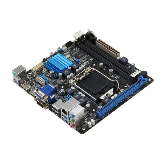
17.0cm(6.7in) DEBUG1 USB89 USB1011 COM1 KBMS1 COM1 _VSET1 SYS_FAN1 LVDS1 CLRTC1 75118 CPU_FAN1 Intel ® PS161 Super SATA6G_1 SATA3G_1 PS161 ATMODE Place this side towards the rear of the chassis USB45 EATX_PWR2 LAN1_USB3 8111E LED2 LED1 AUDIO PCIEX16_1 EMB-B75B... - Page 11 Connectors/Jumpers/Slots Page Backlight inverter power connector (5-pin INV1) 2-23 Intel B75 Serial ATA 6.0Gb/s connector (7-pin SATA6G_1) 2-20 ® BIOS Programmable Connector (8-pin U12) 2-23 Intel B75 Serial ATA 3.0Gb/s connectors (7-pin SATA3G_1) 2-20 ® LVDS connector (30-pin LVDS1) 2-22 LVDS panel voltage selection (3-pin J1) 2-14 USB 2.0 connectors (10-1 pin USB89, USB1011)
-
Page 12: Screw Size
Screw size 2.3.1 Component side EMB-B75B... -
Page 13: Solder Side
2.3.2 Solder side Chapter 2: Motherboard information... -
Page 14: Central Processing Unit (Cpu)
The motherboard comes with a surface mount LGA1155 socket designed for the Intel 2nd Generation Core™ i7 / Core™ i5 / Core™ i3 processors. ® EMB-B75B CPU socket LGA1155 IMPORTANT: Unplug all power cables before installing the CPU. CAUTION! •... -
Page 15: Installing The Cpu
2.4.1 Installing the CPU CAUTION! The LGA1156 CPU is incompatible with the LGA1155 socket. DO NOT install a LGA1156 CPU on the LGA1155 socket. Chapter 2: Motherboard information... - Page 16 EMB-B75B...
-
Page 17: Cpu Heatsink And Fan Assembly Installation
2.4.2 CPU heatsink and fan assembly installation CAUTION! Apply the Thermal Interface Material to the CPU heatsink and CPU before you install the heatsink and fan if necessary. To install the CPU heatsink and fan assembly Chapter 2: Motherboard information... - Page 18 To uninstall the CPU heatsink and fan assembly EMB-B75B 2-10...
-
Page 19: System Memory
System memory 2.5.1 Installing a DIMM To remove a DIMM Chapter 2: Motherboard information 2-11... -
Page 20: Jumpers
CLRTC1 Normal Clear RTC (Default) EMB-B75B Clear RTC RAM To erase the RTC RAM: Turn OFF the computer and unplug the power cord. Move the jumper cap from pins 1-2 (default) to pins 2-3. Keep the cap on pins 2-3 for about 5~10 seconds, then move the cap back to pins 1-2. - Page 21 AT Mode (ATMODE) ATMODE ATMODE ATXMODE (Default) EMB-B75B ATMODE setting AT MODE ATX MODE COM1 Ring/+5V/+12V selection (COM1_VSET1) COM1_VSET1 PIN 1 EMB-B75B COM VSET connector +12V Ring Chapter 2: Motherboard information 2-13...
- Page 22 Inverter voltage selection (3-pin J2) +12V (Default) EMB-B75B Inverter Voltage Selection +12V +5V (Default) Inverter Backlight Control mode selection (3-pin J3) DC Voltage Control PWM Control (Default) EMB-B75B Mode Selection for Back Light Control of Inverter DC Voltage Control PWM Control (Default) EMB-B75B 2-14...
-
Page 23: Connectors
Connectors 2.7.1 Rear panel connectors PS/2 Mouse port (green). This port is for a PS/2 mouse. Video Graphics Adapter (VGA) port. This 15-pin port is for a VGA monitor or other VGA-compatible devices. LAN (RJ-45) ports. These ports allow Gigabit connection to a Local Area Network (LAN) through a network hub. - Page 24 Serial ports. These ports connect a modem, or other devices that conform with serial specification. 10. HDMI ports. These ports are for High-Definition Multimedia Interface (HDMI) connectors, and are HDCP compliant allowing playback of HD DVD, Blu-ray, and other protected content. 11. PS/2 Keyboard port (purple). This port is for a PS/2 keyboard. EMB-B75B 2-16...
-
Page 25: Internal Connectors
+5 Volts PSON# +3 Volts -12 Volts +3 Volts +3 Volts PIN 1 EMB-B75B ATX power connectors IMPORTANT: • For a fully configured system, we recommend that you use a power supply unit (PSU) that complies with ATX 12 V Specification 2.0 (or later version) and provides a minimum power of 350 W. • DO NOT forget to connect the 4-pin ATX +12V power plug. Otherwise, the system will not boot up. - Page 26 Connect the fan cables to the fan connectors on the motherboard, ensuring that the black wire of each cable matches the ground pin of the connector. SYS_FAN1 CPU_FAN1 EMB-B75B Fan connectors CAUTION: Do not forget to connect the fan cables to the fan connectors. Insufficient air flow inside the system may damage the motherboard components.
- Page 27 PLED- PLED+ HD_LED+ PIN 1 EMB-B75B System panel connector • System power LED (2-pin PLED) This 2-pin connector is for the system power LED. Connect the chassis power LED cable to this connector. The system power LED lights up when you turn on the system power, and blinks when the system is in sleep mode.
- Page 28 B75 Serial ATA 3.0Gb/s connectors (7-pin SATA3G_1) ® These connectors connect to Serial ATA 3.0 Gb/s hard disk drives and optical drives via Serial ATA 3.0 Gb/s signal cables. EMB-B75B SATA 3.0Gb/s connector NOTES: • You must install Windows XP Service Pack 3 or later version before using ®...
- Page 29 These USB connectors comply with USB 2.0 specification that supports up to 480 Mbps connection speed. USB89 USB1011 PIN 1 PIN 1 EMB-B75B USB2.0 connectors CAUTION! Never connect a 1394 cable to the USB connectors. Doing so will damage the motherboard! NOTE: The USB module cable is purchased separately. Chapter 2: Motherboard information 2-21...
- Page 30 COM1 123.86mm PIN 1 EMB-B75B Serial port connector NOTE: The COM module is purchased separately. LVDS connector (30-pin LVDS) This connector is for a LCD monitor that supports Low-Voltage Differential Signaling (LVDS) interface.
- Page 31 (NC) SPI_MOSI SPI_MISO SPI_CLK SPI_CS# +V3.3SPI PIN 1 EMB-B75B BIOS Programmable Connector 10. Backlight inverter power connector (5-pin INV1) Connect the backlight inverter power cable to this connector. INV1 Back Light Enable Back Light Control Inverter VCC EMB-B75B Inverter Connector...
- Page 32 EMB-B75B 2-24...
-
Page 33: Chapter 3 Bios Setup
Chapter 3 BIOS setup BIOS setup program Use the BIOS Setup program to update the BIOS or configure its parameters. The BIOS screens include navigation keys and brief online help to guide you in using the BIOS Setup program. Entering BIOS Setup at startup To enter BIOS Setup at startup: Press <Delete> during the Power-On Self Test (POST). If you do not press <Delete>, POST continues with its routine. -
Page 34: Bios Menu Screen
For selecting the exit options and loading default settings. Save & Exit For selecting the exit options and loading default settings. To select an item on the menu bar, press the right or left arrow key on the keyboard until the desired item is highlighted. EMB-B75B... -
Page 35: Navigation Keys
3.1.3 Navigation keys At the bottom right corner of a menu screen are the navigation keys for that particular menu. Use the navigation keys to select items in the menu and change the settings. NOTE: Some of the navigation keys differ from one screen to another. 3.1.4 Menu items The highlighted item on the menu bar displays the specific items for that menu. For... -
Page 36: Main Menu
F3: Optimized Defaults F4: Save and Exit ESC: Exit Version 2.15.1236. Copyright (C) 2012, American Megatrends, Inc. 3.2.1 System Time [xx:xx:xx] Allows you to set the system time. 3.2.2 System Date [Day xx/xx/xxxx] Allows you to set the system date. EMB-B75B... -
Page 37: Advanced Menu
Advanced menu The Advanced menu items allow you to change the settings for the CPU and other system devices. Be cautious when changing the settings of the Advanced menu items. Incorrect field values can cause the system to malfunction. Aptio Setup Utility - Copyright (C) 2012 American Megatrends, Inc. Main Advanced Chipset... -
Page 38: Sata Configuration
Serial ATA features. This increases storage performance on random workloads by allowing the drive to internally optimize the order of commands. IDE Legacy/Native Mode Selection [Native] Allows you to select the SATA mode selection. Configuration options: [Native] [Legacy] EMB-B75B... -
Page 39: Usb Configuration
3.3.4 USB Configuration The items in this menu allow you to configure USB support. The USB Devices item shows the auto-detected values. If no USB device is detected, the item shows None. Legacy USB Support [Enabled] [Enabled] Enables support for USB devices on legacy operating systems. [Disabled] The USB devices can be used only in BIOS setup. [Auto] Allows the system to detect the presence of USB devices at startup. -
Page 40: H/W Monitor
Allows you to enable or disable system wake on alarm event. When enabled, the exact time for the system to wake up can be specified. Configuration options: [Enabled] [Disabled] The following items appear when you set the Wake system with Fixed Time item to [Enabled]. Wake up day/Wake up hour/Wake up minute/Wake up second You can input specific time values for the day, hour, minute, and seconds for when the system will wake up. EMB-B75B... - Page 41 Wake system with Dynamic Time [Disabled] Allows you to enable or disable system wake on alarm event. When enabled, the system will wake up at the current time plus the specified number of minutes. Configuration options: [Enabled] [Disabled] The following item appears when you set the Wake system with Dynamic Time item to [Enabled]. Wake up minute increase You can input the number of minutes added to the current time before the system wakes up.
-
Page 42: Chipset
The system goes into on state after an AC power loss. [Power Off] The system goes into off state after an AC power loss. [Last State] The system goes into either off or on state, whatever the system state was before the AC power loss. EMB-B75B 3-10... -
Page 43: System Agent (Sa) Configuration
3.4.2 System Agent (SA) Configuration Graphics Configuration Allows you to configure the graphics settings. Primary Display [Auto] Select which graphics device would be used as primary display. Configuration options: [Auto] [IGFX] [PEG] [PCI] Internal Graphics [Auto] Configure IGD support for display. Configuration options: [Auto] [Disabled] [Enabled] DVMT Pre-Allocated [64M] Select DVMT 5.0 Pre-Allocated graphics memory size used by the Internal Graphics Device. Configuration options: [32M, 64M, 96M ~ 1024M] DVMT Total Gfx Mem [MEM] Select DVMT 5.0 total graphics memory size used by the Internal Graphics Device. -
Page 44: Boot
The number of device items displayed are dependent on the number of bootable storage devices installed on the system. Configuration options: [Enabled] [Disabled] Hard Drive BBS Priorities This item specifies the boot device priority sequence from the available legacy devices. The number of legacy device items displayed are dependent on the number of bootable legacy storage devices installed on the system. Configuration options: [Enabled] [Disabled] EMB-B75B 3-12... -
Page 45: Security Menu
Security menu The Security menu items allow you to change the system security settings. Administrator Password If you have set an administrator password, we recommend that you enter the administrator password for accessing the system. Otherwise, you might be able to see or change only selected fields in the BIOS setup program. -
Page 46: User Password
From the Create New Password box, key in a new password, then press <Enter>. Confirm the password when prompted. To clear the user password, follow the same steps as in changing a user password, but press <Enter> when prompted to create/confirm the password. After you clear the password, the User Password item on top of the screen shows Not Installed. EMB-B75B 3-14... -
Page 47: Save & Exit Menu
Save & Exit menu The Save & Exit menu items allow you to load the optimal default values for the BIOS items, and save or discard your changes to the BIOS items. Save Changes and Reset This option allows you to save the changes and exit the Setup program. Discard Changes and Reset This option allows you to exit the Setup program without saving your changes. - Page 48 EMB-B75B 3-16...
-
Page 49: Appendix
Check local regulations for disposal of electronic products. DO NOT throw the mercury-containing button cell battery in municipal waste. This symbol of the crossed out wheeled bin indicates that the battery should not be placed in municipal waste. EMB-B75B... - Page 50 印 刷 電 路 板 及 其 × ○ ○ ○ ○ ○ 電子組件 外 部 信 號 連 接 頭 × ○ ○ ○ ○ ○ 及線材 ○: 表示該有毒有害物質在該部件所有均質材料中的含量均在 SJ/T 11363- 2006 標准規定的限量要求以下。 ×: 表示該有毒有害物質至少在該部件的某一均質材料中的含量超出 SJ/T 11363-2006 標准規定的限量要求,然該部件仍符合歐盟指令 2002/95/ EC 的規范。 備註:此產品所標示之環保使用期限,係指在一般正常使用狀況下。 EMB-B75B...