Table of Contents
Advertisement
Advertisement
Table of Contents

Related Manuals for Aaeon EMB-B75A


Summary of Contents for Aaeon EMB-B75A
- Page 1 EMB-B75A...
- Page 2 E11479 Revised Edition V2 March 2016 Copyright Notice This document is copyrighted, 2016. All rights are reserved. The original manufacturer reserves the right to make improvements to the products described in this manual at any time without notice. No part of this manual may be reproduced, copied, translated, or transmitted in any form or by any means without the prior written permission of the original manufacturer.
-
Page 3: Table Of Contents
Contents Chapter 1: Product overview Package contents................. 1-1 Features ..................1-1 Specifications ................1-2 Chapter 2: Motherboard information Before you proceed ..............2-1 Motherboard layout ..............2-2 Screw size ..................2-4 2.3.1 Component side .............. 2-4 2.3.2 Solder side ..............2-5 Central Processing Unit (CPU) ........... - Page 4 Contents Advanced menu ................3-5 3.3.1 ACPI Setting ..............3-5 3.3.2 Trusted Computing ............3-5 3.3.3 CPU Configuration ............3-5 3.3.4 Digital IO ................. 3-6 3.3.5 SATA Configuration ............3-6 3.3.6 USB Configuration ............3-7 3.3.7 Super IO Configuration ........... 3-7 3.3.8 H/W Monitor ..............3-8 Chipset ..................
-
Page 5: Package Contents
Chapter 1 Product overview Package contents Check your industrial motherboard package for the following items. 1 x Industrial Motherboard 1 x Cable Kit 1 x I/O Shield 1 x DVD-ROM for manual (in PDF format) and drivers NOTE: If any of the above items is damaged or missing, contact your distributor or sales representative immediately. -
Page 6: Specifications
6.7 in. x 6.7 in. (17.0 cm x 17.0 cm) Gross weight 1.1 lb (0.5 Kg) Operating F~140 F (0 C~60oC) temperature Storage temperature F~176 F (-40 C~80 Operating humidity 0%~90% relative humidity, non-condensing Power compliance Compliant with Eup/ErP Certificate CE/FCC Class A (continued on the next page) EMB-B75A... - Page 7 DISPLAY Chipset Intel Ivy Bridge +B75 ® Up to 1920x1200@60Hz for CRT Resolution Up to 1920x1080@60Hz for HDMI Maximum shared system memory up to 1748MB Output interface 1 x VGA port 3 x HDMI ports (1 x HDMI ports; 3 x DP to HDMI ports) on rear I/O Storage 1 x SATA 6.0Gb/s port 2 x SATA 3.0Gb/s ports...
- Page 8 EMB-B75A...
-
Page 9: Chapter 2: Motherboard Information
LEDs. LED2 Standby Power Powered Off LED1 Main Power Powered Off EMB-B75A Onboard LED Chapter 2: Motherboard information... -
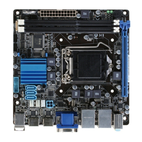
Page 10: Motherboard Layout
USB89 USB1011 COM1 KBMS1 COM2 COM1 USB3_23 _VSET1 CLRTC1 SATA6G_1 SYS_FAN1 Intel ® Dio1 PS161 Super CPU_FAN1 SATA_PWR1 PS161 ATMODE EATX_PWR2 1442 Place this side towards the rear of the chassis 8111F LAN2_USB2 LAN1_USB3 8111E LED2 LED1 AUDIO PCIEX16_1 EMB-B75A... - Page 11 Connectors/Jumpers/Slots Page ATX power connectors (24-pin EATX_PWR1, 4-pin EATX_PWR2) 2-16 SATA Power connector (SATA_POWER) 2-23 CPU and system fan connectors (4-pin CPU_FAN1, 4-pin SYS_FAN1) 2-17 Intel B75 Serial ATA 6.0Gb/s connector (7-pin SATA6G_1) 2-19 ® Intel B75 Serial ATA 3.0Gb/s connectors (7-pin SATA3G_1~2) 2-19 ® USB 3.0 connector (20-1 pin USB3_23) 2-20 USB 2.0 connectors (10-pin USB89, USB1011) 2-21 Clear RTC RAM (3-pin CLRTC) 2-12 Serial port connector (10-pin COM1, COM2) 2-22 10. DDR3 DIMM slots 2-11 11. System panel connector (10-1 pin F_PANEL) 2-18 12. COM1 Ring/+5V/+12V selection (COM1_VSET1) 2-13 13. Main and Standby Power LEDs (LED1, LED2) 14. AT Mode (ATMODE) 2-13 15. Intel LGA1155 CPU socket ®...
-
Page 12: Screw Size
Screw size 2.3.1 Component side 171.58 168.54 162.31 161.51 152.94 142.42 141.58 125.35 124.30 111.79 104.61 103.66 92.74 89.12 81.37 74.96 55.31 52.05 48.25 46.94 41.19 35.99 30.00 20.23 13.54 12.29 8.86 4.86 0.00 36.92 EMB-B75A... -
Page 13: Solder Side
2.3.2 Solder side 170.00 165.01 125.04 105.54 100.60 87.54 69.54 57.35 50.04 32.93 10.07 0.00 Chapter 2: Motherboard information... -
Page 14: Central Processing Unit (Cpu)
Central Processing Unit (CPU) The motherboard comes with a surface mount LGA1155 socket designed for the Intel 2nd Generation Core™ i7 / Core™ i5 / Core™ i3 processors. ® EMB-B75A CPU socket LGA1155 IMPORTANT: Unplug all power cables before installing the CPU. CAUTION! • Upon purchase of the motherboard, ensure that the PnP cap is on the socket and the socket contacts are not bent. Contact your retailer immediately if the PnP cap is missing, or if you see any damage to the PnP cap/socket contacts/motherboard components. The manufacturer will shoulder the cost of repair only if the damage is shipment/transit-related. • Keep the cap after installing the motherboard. The manufacturer will process Return Merchandise Authorization (RMA) requests only if the motherboard comes with the cap on the LGA1155 socket. • The product warranty does not cover damage to the socket contacts resulting from incorrect CPU installation/removal, or misplacement/loss/ incorrect removal of the PnP cap. EMB-B75A... -
Page 15: Installing The Cpu
2.4.1 Installing the CPU CAUTION! The LGA1156 CPU is incompatible with the LGA1155 socket. DO NOT install a LGA1156 CPU on the LGA1155 socket. Chapter 2: Motherboard information... - Page 16 EMB-B75A...
-
Page 17: Cpu Heatsink And Fan Assembly Installation
2.4.2 CPU heatsink and fan assembly installation CAUTION! Apply the Thermal Interface Material to the CPU heatsink and CPU before you install the heatsink and fan if necessary. To install the CPU heatsink and fan assembly Chapter 2: Motherboard information... - Page 18 To uninstall the CPU heatsink and fan assembly EMB-B75A 2-10...
-
Page 19: System Memory
System memory 2.5.1 Installing a DIMM To remove a DIMM Chapter 2: Motherboard information 2-11... -
Page 20: Jumpers
CLRTC Normal Clear RTC (Default) EMB-B75A Clear RTC RAM To erase the RTC RAM: Turn OFF the computer and unplug the power cord. 2. Move the jumper cap from pins 1-2 (default) to pins 2-3. Keep the cap on pins 2-3 for about 5~10 seconds, then move the cap back to pins 1-2. Plug the power cord and turn ON the computer. - Page 21 AT Mode (ATMODE) AT MODE ATX MODE COM1 Ring/+5V/+12V selection (COM1_VSET1) Com1_Vset1 PIN 1 EMB-B75A COM VSET connectors +12V Ring Chapter 2: Motherboard information 2-13...
-
Page 22: Connectors
ORANGE Linked ORANGE 100 Mbps connection LAN port BLINKING Data activity GREEN 1 Gbps connection Line In port (light blue). This port connects the tape, CD, DVD player, or other audio sources. Line Out port (lime). This port connects to a headphone or a speaker. In 4- channel and 6-channel configurations, the function of this port becomes Front Speaker Out. Microphone port (pink). This port connects a microphone. NOTE: Refer to the audio configuration table on the next page for the function of the audio ports in the 2, 4, or 6-channel configuration. EMB-B75A 2-14... - Page 23 Audio 2, 4, 6-channel configuration Port 2-channel 4-channel 6-channel Light Blue (Rear Rear Speaker Rear Speaker Line In panel) Front Front Lime (Rear panel) Line Out Speaker Out Speaker Out Pink (Rear panel) Mic In Mic In Bass/Center Lime (Front panel) USB 3.0 ports. These two 9-pin Universal Serial Bus (USB) ports connect to USB 3.0/2.0 devices. NOTES: • DO NOT connect a keyboard / mouse to any USB 3.0 port when installing Windows operating system. ® • Due to USB 3.0 controller limitation, USB 3.0 devices can only be used under Windows OS environment and after the USB 3.0 driver installation. ®...
-
Page 24: Internal Connectors
+5 Volts Power OK -5 Volts +5 Volts +5 Volts PSON# +3 Volts -12 Volts +3 Volts +3 Volts PIN 1 EMB-B75A ATX power connectors IMPORTANT: • For a fully configured system, we recommend that you use a power supply unit (PSU) that complies with ATX 12 V Specification 2.0 (or later version) and provides a minimum power of 350 W. • DO NOT forget to connect the 4-pin ATX +12V power plug. Otherwise, the system will not boot up. • We recommend that you use a PSU with higher power output when configuring a system with more power-consuming devices. The system may become unstable or may not boot up if the power is inadequate. - Page 25 CPU and system fan connectors (4-pin CPU_FAN1, 4-pin SYS_FAN1) Connect the fan cables to the fan connectors on the motherboard, ensuring that the black wire of each cable matches the ground pin of the connector. SYS_FAN CPU_FAN EMB-B75A Fan connectors CAUTION: Do not forget to connect the fan cables to the fan connectors. Insufficient air flow inside the system may damage the motherboard components. These are not jumpers! Do not place jumper caps on the fan...
- Page 26 F_PANEL (NC) HWRST# PANSWH# HD_LED- PLED- HD_LED+ PLED+ PIN 1 EMB-B75A System panel connector • System power LED (2-pin PLED) This 2-pin connector is for the system power LED. Connect the chassis power LED cable to this connector. The system power LED lights up when you turn on the system power, and blinks when the system is in sleep mode. • Hard disk drive activity LED (2-pin +HDLED) This 2-pin connector is for the HDD Activity LED. Connect the HDD Activity LED cable to this connector. The IDE LED lights up or flashes when data is...
- Page 27 Intel B75 Serial ATA 3.0Gb/s connectors (7-pin SATA3G_1~2) ® These connectors connect to Serial ATA 3.0 Gb/s hard disk drives and optical drives via Serial ATA 3.0 Gb/s signal cables. EMB-B75A SATA 3.0Gb/s connectors NOTES: • You must install Windows XP Service Pack 3 or later version before using ® Serial ATA hard disk drives. • When using hot-plug and NCQ, set the SATA Mode Selection item in the BIOS to [AHCI]. See section 3.3.5 SATA Configuration for details. Intel B75 Serial ATA 6.0Gb/s connector (7-pin SATA6G_1) ® ThIS connector connects to Serial ATA 6.0 Gb/s hard disk drives via Serial ATA 6.0 Gb/s signal cables. EMB-B75A SATA 6.0Gb/s connector NOTES: •...
- Page 28 USB 3.0 connector (20-1 pin USB3_23) This connector is for the additional USB 3.0 ports. Connect the USB 3.0 bracket cable to this connector, then install the USB 3.0 bracket to the rear side of the chassis. If your chassis support customized front panel installation, with USB 3.0 header, you can have a front panel USB 3.0 solution. USB3_23 PIN 1 EMB-B75A USB3.0 Front panel connector NOTES: • The USB 3.0 module is purchased separately. • Due to Intel limitations, the USB3_34 only supports Windows 7 operating ® ® system. EMB-B75A 2-20...
- Page 29 USB 2.0 connectors (10-1 pin USB89, USB1011) These connectors are for USB 2.0 ports. Connect the USB module cable to any of these connectors, then install the module to a slot opening at the back of the system chassis. These USB connectors comply with USB 2.0 specification that supports up to 480 Mbps connection speed. USB89 USB1011 PIN 1 PIN 1 EMB-B75A USB2.0 connectors CAUTION! Never connect a 1394 cable to the USB connectors. Doing so will damage the motherboard! NOTE: The USB module cable is purchased separately. Chapter 2: Motherboard information 2-21...
- Page 30 Serial port connectors (10-1 pin COM1, COM2) These connectors are for serial (COM) ports. Connect the serial port module cable to this connector, then install the module to a slot opening at the back of the system chassis. COM2 COM1 PIN 1 PIN 1 EMB-B75A Serial port connectors NOTES: • The COM module is purchased separately. • COM1 also supports RS-232 / RS-422 / RS-485. See the table below and section 3.3.7 Super IO Configuration for details. Signal Signal DCD (422TXD-/485DATA-) RXD (422RXD+) TXD (422TXD+/485DATA+)
- Page 31 DIO connector DIO1 PIN 1 EMB-B75A DIO connector 10. SATA power connector (SATA_POWER) EMB-B75A SATA_POWER connector Chapter 2: Motherboard information 2-23...
- Page 32 EMB-B75A 2-24...
-
Page 33: Chapter 3: Bios Setup
Chapter 3 BIOS setup BIOS setup program Use the BIOS Setup program to update the BIOS or configure its parameters. The BIOS screens include navigation keys and brief online help to guide you in using the BIOS Setup program. Entering BIOS Setup at startup To enter BIOS Setup at startup: •... -
Page 34: Bios Menu Screen
Aptio Setup Utility - Copyright (C) 2011 American Megatrends, Inc. Main Advanced Chipset Boot Security Save & Exit Set the Date. Use Tab BIOS Information to switch between EMB-B75A R0.4(EM75A04) (05/21/2012 Date elements. BIOS Vendor American Megatrends Core Version 4.6.5.3 Compliancy UEFI 2.3; PI 1.2 System Date [Mon 12/14/2009]... -
Page 35: Navigation Keys
3.1.3 Navigation keys At the bottom right corner of a menu screen are the navigation keys for that particular menu. Use the navigation keys to select items in the menu and change the settings. NOTE: Some of the navigation keys differ from one screen to another. 3.1.4 Menu items The highlighted item on the menu bar displays the specific items for that menu. -
Page 36: Main Menu
F3: Optimized Defaults F4: Save and Exit ESC: Exit Version 2.14.1219. Copyright (C) 2011, American Megatrends, Inc. 3.2.1 System Time [xx:xx:xx] Allows you to set the system time. 3.2.2 System Date [Day xx/xx/xxxx] Allows you to set the system date. EMB-B75A... -
Page 37: Advanced Menu
Advanced menu The Advanced menu items allow you to change the settings for the CPU and other system devices. Be cautious when changing the settings of the Advanced menu items. Incorrect field values can cause the system to malfunction. Aptio Setup Utility - Copyright (C) 2011 American Megatrends, Inc. Main Advanced Chipset... -
Page 38: Digital Io
Serial ATA features that increases storage performance on random workloads by allowing the drive to internally optimize the order of commands. IDE Legacy/Native Mode Selection [Native] Allows you to select the SATA mode selection. Configuration options: [Native] [Legacy] EMB-B75A... -
Page 39: 3.3.6 Usb Configuration
3.3.6 USB Configuration The items in this menu allow you to change the USB-related features. The USB Devices item shows the auto-detected values. If no USB device is detected, the item shows None. Legacy USB Support [Enabled] [Enabled] Enables the support for USB devices on legacy operating systems (OS). -
Page 40: H/W Monitor
<Enter> to display the sub-menu. 3.4.1 PCH-IO Configuration PCIE Express Configuration Allows you to configure the PCI Express settings. USB Configuration Allows you to configure the USB settings. PCH Azalia Configuration Allows you to configure the PCH Azalia settings. EMB-B75A... - Page 41 BIOS Security Configuration Allows you to configure the BIOS Security settings. Power Mode [Enabled] Allows you to select the power supply type. Configuration options: [ATX Type] [AT Type] Resume on PCIE Wake [Enabled] Allows you to enable or disable PCIE devices to generate a wake event. Configuration options: [Enabled] [Disabled] Resume on PCI PME [Enabled] Allows you to enable or disable the PCI PME wake function.
-
Page 42: System Agent (Sa) Configuration
Allows you to enable or disable the C-State Pre-Wake feature. Configuration options: [Enabled] [Disabled] Graphics Configuration Allows you to configure the graphics settings. DMI Configuration Allows you to control various DMI functions. NB PCIe Configuration Allows you to configure the NB PCI Express settings. EMB-B75A 3-10... -
Page 43: Boot Menu
Memory Configuration Allows you to configure the memory settings. Memory Thermal Configuration Allows you to configure the Memory Thermal settings. GT-Power Management Control Allows you to configure the Power Management Control settings. Boot menu The Boot menu items allow you to change the system boot options. 3.5.1 Boot Configuration Quiet Boot [Enabled]... -
Page 44: Security Menu
To clear the administrator password, follow the same steps as in changing an administrator password, but press <Enter> when prompted to create/confirm the password. After you clear the password, the Administrator Password item on top of the screen shows Not Installed. EMB-B75A 3-12... -
Page 45: User Password
User Password If you have set a user password, you must enter the user password for accessing the system. The User Password item on top of the screen shows the default Not Installed. After you set a password, this item shows Installed. To set a user password: Select the User Password item and press <Enter>. - Page 46 Select Yes to load the default values. Save as User Defaults This option allows you to save the current changes as the user’s default values. Restore User Defaults This option allows you to load the user’s default values. EMB-B75A 3-14...
-
Page 47: Appendix
• Consult the dealer or an experienced radio/TV technician for help. WARNING! The use of shielded cables for connection of the monitor to the graphics card is required to assure compliance with FCC regulations. Changes or modifications to this unit not expressly approved by the party responsible for compliance could void the user’s authority to operate this equipment. EMB-B75A... - Page 48 EMB-B75A...