Table of Contents
Advertisement
Quick Links
Advertisement
Table of Contents

Related Manuals for Aaeon EMB-Q87B


Summary of Contents for Aaeon EMB-Q87B
- Page 1 EMB-Q87B...
- Page 2 E9749 First Edition November 2014 Copyright Notice This document is copyrighted, 2014. All rights are reserved. The original manufacturer reserves the right to make improvements to the products described in this manual at any time without notice. No part of this manual may be reproduced, copied, translated, or transmitted in any form or by any means without the prior written permission of the original manufacturer.
-
Page 3: Table Of Contents
Contents Chapter 1: Product overview Package contents................. 1-1 Features ..................1-1 Specifications ................1-2 Chapter 2: Motherboard information Before you proceed ..............2-1 Motherboard layout ..............2-2 Screw size ..................2-4 2.3.1 Component side .............. 2-4 2.3.2 Solder side ..............2-5 Central Processing Unit (CPU) ........... - Page 4 3.3.7 PCH-FW Configuration ........... 3-6 3.3.8 AMT Configuration ............3-6 3.3.9 USB Configuration ............3-7 3.3.10 NCT6791D Super IO Configuration ........ 3-7 3.3.11 NCT6791D HW Monitor ..........3-7 Chipset ..................3-8 3.4.1 System Agent (SA) Configuration ........3-8 3.4.2 PCH-IO Configuration ............. 3-8 Boot menu ..................3-9 Security menu ................3-10 Save &...
-
Page 5: Chapter 1: Product Overview
Chapter 1 Product overview Package contents Check your industrial motherboard package for the following items. 1 x Industrial Motherboard 1 x I/O Shield 1 x SATA cable and SATA power cable 1 x Support CD If any of the above items is damaged or missing, contact your distributor or sales representative immediately. -
Page 6: Specifications
Yes (WOL / PXE) Power State S3, S4, S5 GRAPHICS Intel HD Graphics Graphics Chipset ® DP, DP+DP, DP+DP+DP Graphics Multi Display Up to 3840 x 2160 @60 Hz, with Digital Audio Display Port (continued on the next page) EMB-Q87B... - Page 7 Storage 4 x SATA 6Gb/s 1 x Full/ Half size Mini Card (PCIe or mSATA select by jumper; default: mSATA 6.0Gb/s) 1 x Half size Mini Card (PCIe or mSATA select by jumper; default: PCIe +USB) 4-pin SATA power (5V, 12V @3A) 4 x USB 3.0 ports(Rear IO), 8 x USB 2.0 ports (6 ports are pin headers and 2 ports are vertical at mid board) Display I/O...
- Page 8 ME jumper ® 1 x Battery connector 1 x SATA power connector 1 x mSATA/PCIe mode selection jumper 1 x SPI flash programmable connector Others Windows 7 32 / 64 bit OS Support ® Windows 8 32 / 64 bit ® Linux Fedora NOTE: Specifications are subject to change without notice. EMB-Q87B...
-
Page 9: Chapter 2: Motherboard Information
Chapter 2 Motherboard information Before you proceed Take note of the following precautions before you install motherboard components or change any motherboard settings. CAUTION! • Unplug the power cord from the wall socket before touching any component. • Before handling components, use a grounded wrist strap or touch a safely grounded object or a metal object, such as the power supply case, to avoid damaging them due to static electricity. • Hold components by the edges to avoid touching the ICs on them. • Whenever you uninstall any component, place it on a grounded antistatic pad or in the bag that came with the component. • Before you install or remove any component, always remove the AC power by unplugging the power cord from the power outlet. -
Page 10: Motherboard Layout
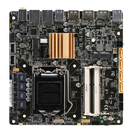
DISPLAYPORT2 DDR3 DIMM_B1 (64bit, 204-pin module) SPI_1 USB1112 USB78 USB56 PCIE_SET Place this side DISPLAYPORT3 towards the rear of the chassis Intel ® USB3_56 Intel PHY LGA1150 I217LM BATTERY1 LAN1 MINICARD1 LAN2 Intel I210AT AUDIO DIS_ME USB2 USB3 AAFP EMB-Q87B... - Page 11 Connectors/Jumpers/Slots Page Mini Card slots (MINICARD1, MINICARD2) 2-20 2-19 PS/2 keyboard/mouse connector (6-pin KBMS) DC power connector (4-pin DC_PWR2) 2-16 Serial ATA 6.0Gb/s connectors (7-pin SATA6G_1~4) 2-20 2-17 Serial port connectors (10-1 pin COM1, COM2) COM1 Ring/+5V/+12V selection (6-pin COM1_VSET) 2-13 CPU and chassis fan connectors (4-pin CPU_FAN, 4-pin CHA_FAN) 2-17 Standby power LED (SB_PWR, VS_PWR) 2-14 Digital I/O connector (10-pin DIO) 2-18 10. System panel connector (10-1 pin F_PANEL) 2-19 11. Chassis intrusion connector (4-1 pin CHASSIS) 2-18 12. Clear RTC RAM (3-pin CLRTC) 2-12 13. Intel LGA1150 CPU socket ® 14. Intel ME jumper (3-pin DIS_ME) 2-13 ® 15. SO-DIMM slots 2-11 16.
-
Page 12: Screw Size
Screw size 2.3.1 Component side EMB-Q87B... -
Page 13: Solder Side
2.3.2 Solder side Chapter 2: Motherboard information... -
Page 14: Central Processing Unit (Cpu)
Central Processing Unit (CPU) The motherboard comes with a surface mount LGA1150 socket designed for the Intel Haswell 22nm processors. ® EMB-Q87B CPU socket LGA1150 IMPORTANT: Unplug all power cables before installing the CPU. CAUTION! • Upon purchase of the motherboard, ensure that the PnP cap is on the socket and the socket contacts are not bent. Contact your retailer immediately if the PnP cap is missing, or if you see any damage to the PnP cap/socket contacts/motherboard components. • Keep the cap after installing the motherboard. The manufacturer will process Return Merchandise Authorization (RMA) requests only if the motherboard comes with the cap on the LGA1150 socket. • The product warranty does not cover damage to the socket contacts resulting from incorrect CPU installation/removal, or misplacement/loss/incorrect removal of the PnP cap. EMB-Q87B... -
Page 15: Installing The Cpu
2.4.1 Installing the CPU CAUTION! The LGA1156 CPU is incompatible with the LGA1150 socket. DO NOT install a LGA1156 CPU on the LGA1150 socket. Chapter 2: Motherboard information... -
Page 16: Cpu Heatsink And Fan Assembly Installation
2.4.2 CPU heatsink and fan assembly installation CAUTION! Apply the Thermal Interface Material to the CPU heatsink and CPU before you install the heatsink and fan if necessary. EMB-Q87B... - Page 17 To install the CPU heatsink and fan assembly Chapter 2: Motherboard information...
- Page 18 To uninstall the CPU heatsink and fan assembly EMB-Q87B 2-10...
-
Page 19: System Memory
System memory This motherboard comes with two Double Data Rate 3 (DDR3) Small Outline Dual Inline Memory Module (SO-DIMM) sockets. A DDR3 module has the same physical dimensions as a DDR2 DIMM but is notched differently to prevent installation on a DDR2 DIMM socket. DDR3 modules are developed for better performance with less power consumption. The figure below illustrates the location of the DDR3 DIMM sockets: Channel Sockets DIMM_A1 DIMM_B1 Channel A SO_DIMM_A1 Channel B SO_DIMM_B1 EMB-Q87B 204-pin DDR3 SO-DIMM sockets Installing a DIMM To install a DIMM To remove a DIMM Chapter 2: Motherboard information 2-11... -
Page 20: Jumpers
Jumpers Clear RTC RAM (3-pin CLRTC) This jumper allows you to clear the Real Time Clock (RTC) RAM in CMOS. You can clear the CMOS memory of system setup parameters by erasing the CMOS RTC RAM data. The onboard button cell battery powers the RAM data in CMOS, which include system setup information such as system passwords. EMB-Q87B Clear RTC RAM To erase the RTC RAM: 1. Turn OFF the computer and unplug the power cord. 2. Move the jumper cap from pins 1-2 (default) to pins 2-3. Keep the cap on pins 2-3 for about 5~10 seconds, then move the cap back to pins 1-2. 3. Plug the power cord and turn ON the computer. 4. Hold down the <Del> key during the boot process and enter BIOS setup to reenter data. CAUTION! Except when clearing the RTC RAM, never remove the cap on CLRTC jumper default position. Removing the cap will cause system boot failure! NOTES: • If the steps above do not help, remove the onboard battery and move the jumper again to clear the CMOS RTC RAM data. After clearing the CMOS, reinstall the battery. - Page 21 Ring (Default) mSATA/PCIe mode selection (6-pin PCIE_SET) PCIE_SET for Mini card 1 PCIE_SET for Mini card 2 mSATA PCIe mSATA PCIe (Default) (Default) EMB-Q87B Minicard mSATA/PCIe mode selection Setting Pins PCIE_SET for mSATA Mini card 1 PCIe (Default) PCIE_SET for mSATA (Default) Mini card 2...
-
Page 22: Onboard Leds
Onboard LEDs Standby Power LED The motherboard comes with a standby power LED that lights up to indicate that the system is ON, in sleep mode, or in soft-off mode. This is a reminder that you should shut down the system and unplug the power cable before removing or plugging in any motherboard component. The illustration below shows the location of the onboard LED. VS_PWR Main Power Main Power Off SB_PWR Standby Power Powered Off EMB-Q87B Onboard LEDs EMB-Q87B 2-14... -
Page 23: Connectors
Connectors 2.8.1 Rear panel connectors USB 3.0 ports. These 9-pin Universal Serial Bus (USB) ports connect to USB 3.0/2.0 devices. NOTES: • DO NOT connect a keyboard / mouse to any USB 3.0 port when installing Windows operating system. ® • Due to USB 3.0 controller limitation, USB 3.0 devices can only be used under Windows OS environment and after the USB 3.0 driver installation. ® • USB 3.0 devices can only be used as data storage only. • We strongly recommend that you connect USB 3.0 devices to USB 3.0 ports for faster and better performance for your USB 3.0 devices. DisplayPort. These ports connect a DisplayPort monitor or a home-theater system. LAN (RJ-45) ports. These ports allow Gigabit connection to a Local Area Network (LAN) through a network hub. Refer to the table below for the LAN port LED indications. -
Page 24: Internal Connectors
PIN 1 EMB-Q87B DC power connector SATA power connector (4-pin SATA_PWR) This connector is for the SATA power cable. The power cable plug is designed to fit this connector in only one orientation. Find the proper orientation and push down firmly until the connector completely fit. SATA_PWR PIN 1 +12V EMB-Q87B SATA power connector Front panel audio connector (10-1 pin AAFP) This connector is for a chassis-mounted front panel audio I/O module. Connect one end of the front panel audio I/O module cable to this connector. AAFP PIN 1 EMB-Q87B Front panel audio connector EMB-Q87B 2-16... - Page 25 CAUTION: Do not forget to connect the fan cables to the fan connectors. Insufficient air flow inside the system may damage the motherboard components. These are not jumpers! Do not place jumper caps on the fan connectors! NOTE: The CPU_FAN connector supports a CPU fan of maximum 2A (24 W) fan power. Serial port connectors (10-1 pin COM1, COM2) These connectors are for serial (COM) ports. Connect the serial port cables to these connectors, then install the module to a slot opening at the back of the system chassis. COM2 COM1 PIN 1 PIN 1 EMB-Q87B Serial port connectors NOTE: The serial port cables are purchased separately. Chapter 2: Motherboard information 2-17...
- Page 26 CHASSIS Intruder Intruder No Intruder PIN1 EMB-Q87B Chassis intrusion connector Digital I/O connector (10-pin DIO) This connector includes 8 I/O lines (In/Out programmable). All of the Digital I/O lines are programmable and each I/O pin can be individually programmed to support various devices. PIN 1 EMB-Q87B DIO connector NOTE: To configure the I/O pins in BIOS, go to the Advanced tab > Dynamic Digital IO >...
- Page 27 System panel connector (10-1 pin F_PANEL) This connector supports several chassis-mounted functions. F_PANEL (NC) RSTCON# Ground PWRBTN# PWR_LED- HDD_LED- PWR_LED+ HDD_LED+ PIN 1 EMB-Q87B System panel connector • System power LED (2-pin PWR_LED) This 2-pin connector is for the system power LED. Connect the chassis power LED cable to this connector. The system power LED lights up when you turn on the system power, and blinks when the system is in sleep mode. • Hard disk drive activity LED (2-pin HDD_LED) This 2-pin connector is for the HDD Activity LED. Connect the HDD Activity LED cable to this connector. The IDE LED lights up or flashes when data is read from or written to the HDD. • ATX power button/soft-off button (2-pin PWR_BTN) This 2-pin connector is for the system power button.
- Page 28 NOTE: When using hot-plug and NCQ, set the SATA Mode Selection item in the BIOS to [AHCI]. See section 3.3.6 SATA Configuration for details. 12. Minicard connectors Use these connectors to connect a Minicard device. MINICARD2 MINICARD1 EMB-Q87B Minicard connectors NOTE: The Minicard device is purchased separately. SPI flash programmable connector (8-pin SPI_1) Use this connector to flash BIOS SPI ROM. SPI_1 (NC) (NC) SPI_MOSI SPI_MISO SPI_CLK SPI_CS# +3V_SPI PIN 1 EMB-Q87B SPI flash programmable connector EMB-Q87B 2-20...
- Page 29 14. USB 2.0 connectors (4-pin USB2 / USB3; 10-pin USB56, USB78, USB1112) These connectors are for USB 2.0 ports. Connect the USB cable to these connectors. These USB connectors comply with USB 2.0 specification that supports up to 480 Mbps connection speed. USB1112 USB78 USB56 PIN 1 PIN 1 PIN 1 USB2 USB3 PIN 1 PIN 1 EMB-Q87B USB2.0 connectors CAUTION: Never connect a 1394 cable to the USB connector. Doing so will damage the motherboard. NOTE: The USB cable is purchased separately. Chapter 2: Motherboard information 2-21...
- Page 30 EMB-Q87B 2-22...
-
Page 31: Chapter 3: Bios Setup
Chapter 3 BIOS setup BIOS setup program Use the BIOS Setup program to update the BIOS or configure its parameters. The BIOS screens include navigation keys and brief online help to guide you in using the BIOS Setup program. Entering BIOS Setup at startup To enter BIOS Setup at startup: Press <Delete>... -
Page 32: Bios Menu Screen
For changing the security settings. Security For selecting the exit options and loading default settings. Save & Exit To select an item on the menu bar, press the right or left arrow key on the keyboard until the desired item is highlighted. EMB-Q87B... -
Page 33: Main Menu
Main menu When you enter the BIOS Setup program, the Main menu screen appears, giving you an overview of the basic system information. Refer to section 3.1.1 BIOS menu screen for information on the menu screen items and how to navigate through them. Aptio Setup Utility - Copyright (C) 2012 American Megatrends, Inc. -
Page 34: Advanced Menu
Dynamic Digital IO The items in this menu allows you to configure the Digital IO as input or output and Digital IO Output as high or low. DIO0~3 Direction [Input] Allows you to configure the Digital IO. Configuration options: [Input] [Output] EMB-Q87B... -
Page 35: Acpi Settings
DIO4~7 Direction [Output] Allows you to configure the Digital IO. Configuration options: [Input] [Output] Output Level [Hi] Configuration options: [Hi] [Low] 3.3.3 ACPI Settings The items in this menu allows you to configure the system ACPI parameters. ACPI Sleep State [S3 only (Suspend to...] Allows you to select the ACPI sleep state that the system will enter when the SUSPEND button is pressed. -
Page 36: Sata Configuration
The following item becomes configurable only when you set the Intel ® item to [Enabled]. Un-Configure ME [Disabled] Sets this item to [Disabled] to unconfigure AMT/ME without using a password or set it to [Enabled] to use a password. Configuration options: [Enabled] [Disabled] EMB-Q87B... -
Page 37: Usb Configuration
3.3.9 USB Configuration The items in this menu allow you to change the USB-related features. The USB Devices item shows the auto-detected values. If no USB device is detected, the item shows None. Legacy USB Support [Enabled] [Enabled] Enables the support for USB devices on legacy operating systems (OS). -
Page 38: Chipset
PCH-IO Configuration Power Mode [ATX Types] Allows you to select the power supply mode. Configuration options: [ATX Type] [AT Type] Resume on Ring [Enabled] [Disabled] Disables Ring to generate a wake event. [Enabled] Enables Ring to generate a wake event. EMB-Q87B... -
Page 39: Boot Menu
Restore AC Power Loss [Power Off] [Power On] The system goes into on state after an AC power loss. [Power Off] The system goes into off state after an AC power loss. [Last State] The system goes into either off or on state, whatever the system state was before the AC power loss. -
Page 40: Security Menu
Installed. After you set a password, this item shows Installed. To set a user password: Select the User Password item and press <Enter>. From the Create New Password box, key in a password, then press <Enter>. Confirm the password when prompted. Confirm the password when prompted. EMB-Q87B 3-10... -
Page 41: Save & Exit Menu
To clear the user password, follow the same steps as in changing a user password, but press <Enter> when prompted to create/confirm the password. After you clear the password, the User Password item on top of the screen shows Not Installed. Save &... - Page 42 EMB-Q87B 3-12...
-
Page 43: Appendix
Check local regulations for disposal of electronic products. DO NOT throw the mercury-containing button cell battery in municipal waste. This symbol of the crossed out wheeled bin indicates that the battery should not be placed in municipal waste. EMB-Q87B... - Page 44 印 刷 電 路 板 及 其 × ○ ○ ○ ○ ○ 電子組件 外 部 信 號 連 接 頭 × ○ ○ ○ ○ ○ 及線材 ○: 表示該有毒有害物質在該部件所有均質材料中的含量均在 SJ/T 11363- 2006 標准規定的限量要求以下。 ×: 表示該有毒有害物質至少在該部件的某一均質材料中的含量超出 SJ/T 11363-2006 標准規定的限量要求,然該部件仍符合歐盟指令 2002/95/ EC 的規范。 備註:此產品所標示之環保使用期限,係指在一般正常使用狀況下。 EMB-Q87B...