Table of Contents

Related Manuals for Aaeon EMB-BT1


Summary of Contents for Aaeon EMB-BT1
- Page 1 EMB-BT1...
- Page 2 E9987 Revised Edition V4 January 2016 Copyright Notice This document is copyrighted, 2016. All rights are reserved. The original manufacturer reserves the right to make improvements to the products described in this manual at any time without notice. No part of this manual may be reproduced, copied, translated, or transmitted in any form or by any means without the prior written permission of the original manufacturer.
-
Page 3: Table Of Contents
Contents Chapter 1: Product overview Package contents................. 1-1 Features ..................1-1 Specifications ................1-2 Chapter 2: Motherboard information Before you proceed ..............2-1 Motherboard layout ..............2-2 Screw size ..................2-4 2.3.1 Component side .............. 2-4 2.3.2 Solder side ..............2-5 Central Processing Unit (CPU) ........... - Page 4 Contents Chipset menu ................3-8 3.4.1 North Bridge Configuration ..........3-8 3.4.2 South Bridge Configuration ..........3-8 Security menu ................3-9 3.5.1 Administrator Password ..........3-9 3.5.2 User Password ..............3-9 Boot menu .................. 3-10 Boot Configuration ............... 3-10 Save & Exit menu ............... 3-11 Appendix Notices .......................A-1...
-
Page 5: Chapter 1: Product Overview
Chapter 1 Product overview Package contents Check your industrial motherboard package for the following items. 1 x Industrial Motherboard 1 x SATA Cable 1 x I/O Shield 1 x Support CD 1 x SATA power cable If any of the above items is damaged or missing, contact your distributor or sales representative immediately. -
Page 6: Specifications
6.7 in. x 6.7 in. (17.0 cm x 17.0 cm) Gross weight 1.1 lb (0.5 Kg) Operating F~140 F (0 C~60 temperature Storage temperature F~185 F (-40 C~85 Operating humidity 0%~90% relative humidity, non-condensing Power compliance Compliant with Eup/ErP Certificate CE/FCC (continued on the next page) EMB-BT1... - Page 7 DISPLAY Chipset Intel® HD Graphics Up to 1920x1200@60Hz for VGA Resolution Up to 1920x1200@60Hz for HDMI Up to 1920x1080@60Hz, Dual Channel 18/24-bit LVDS Output interface 1 x LVDS 1 x VGA 1 x HDMI Storage 2 x SATA 6.0Gb/s ports 2 x SATA 3.0Gb/s ports (1 colay with mSATA) 1 x SATA power connector 1 x RS-232/422/485 supports 5V/12V/RI option (COM1 for box...
- Page 8 EMB-BT1...
-
Page 9: Chapter 2: Motherboard Information
Chapter 2 Motherboard information Before you proceed Take note of the following precautions before you install motherboard components or change any motherboard settings. CAUTION! • Unplug the power cord from the wall socket before touching any component. • Before handling components, use a grounded wrist strap or touch a safely grounded object or a metal object, such as the power supply case, to avoid damaging them due to static electricity. • Hold components by the edges to avoid touching the ICs on them. • Whenever you uninstall any component, place it on a grounded antistatic pad or in the bag that came with the component. -
Page 10: Motherboard Layout
DDR3_DIMM_A1 (64bit, 240-pin module) USB3_1 USBHUB_56 MINI_CARD1 LAN1 8111G LAN2 Place this side towards the rear 1661 8111G of the chassis HDMI1 BATTERY1 1442 SPI1 64Mb INV1 BIOS LED2 COM1 Super KBMS1 AAFP1 LVDS1 AUDIO1 LPT1 CHRONTEL CH7511 PCIEX1_1 EMB-BT1... - Page 11 Connectors/Jumpers/Slots Page 12VDC connector (4-pin EATX_PWR1) 2-14 USB 2.0 connector (10-1 pin USBHUB_34, USBHUB_56 and USBHUB_7) 2-19 SO-DIMM memory slots Standby Power LED (SB_PWR_LED1, SB_PWR_LED2) 2-11 CPU and chassis fan connectors (4-pin CPU_FAN, CHA_FAN) 2-15 COM1 Ring/+5V/+12V selection (6-pin J1) SATA power connector (SATA_PWR1) 2-17 Minicard connectors (MINI_CARD1, MINI_CARD2) 2-19 10. Serial ATA 6.0Gb/s connectors (7-pin SATA6G_1, SATA6G_2) 2-17 11. Serial ATA 3.0Gb/s connectors (7-pin SATA3G_1, SATA3G_2) 2-22 12. Digital I/O connector (DIO1) 2-22 13. System panel connector (10-1 pin F_PANEL) 2-16 14. Clear RTC RAM (CLRTC) 15. Serial port connectors (10-1 pin COM1, COM3~6) 2-21 16. PS/2 keyboard and mouse connector (KBMS1) 2-20 17. LPT connector (26-1 pin LPT1) 2-20 18. Backlight inverter power connector (5-pin INV1) 2-18 19.
-
Page 12: Screw Size
Screw size 2.3.1 Component side EMB-BT1... -
Page 13: Solder Side
2.3.2 Solder side Chapter 2: Motherboard information... -
Page 14: Central Processing Unit (Cpu)
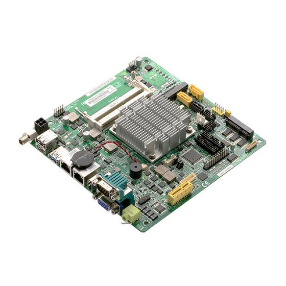
Central Processing Unit (CPU) This motherboard comes with an Intel® J1900/E3845/E3825/N2807 processor. EMB-BT1 CPU System memory This motherboard comes with two Double Data Rate 3 Low Voltage (DD3L) Small Outline Dual Inline Memory Modules (SO-DIMM) socket. The figure illustrates the location of the DDR3L DIMM socket: DIMM_B1 DIMM_A1 EMB-BT1 204-pin DDR3L SO-DIMM sockets NOTE: Use the SO-DIMM_A1 slot when inserting only one SO-DIMM. EMB-BT1... -
Page 15: Installing A Dimm
2.5.1 Installing a DIMM To install a SO-DIMM To remove a SO-DIMM Chapter 2: Motherboard information... -
Page 16: Jumpers
Jumpers Clear RTC RAM (CLRTC) This jumper allows you to clear the Real Time Clock (RTC) RAM in CMOS. You can clear the CMOS memory of system setup parameters by erasing the CMOS RTC RAM data. The onboard button cell battery powers the RAM data in CMOS, which include system setup information such as system passwords. CLRTC Normal Clear RTC1 (Default) EMB-BT1 Clear RTC RAM To erase the RTC RAM: 1. Turn OFF the computer and unplug the power cord. 2. Move the jumper cap from pins 1-2 (default) to pins 2-3. Keep the cap on pins 2-3 for about 5~10 seconds, then move the cap back to pins 1-2. 3. Plug the power cord and turn ON the computer. 4. Hold down the <Del> key during the boot process and enter BIOS setup to reenter data. CAUTION! Except when clearing the RTC RAM, never remove the cap on CLRTC jumper default position. Removing the cap will cause system boot failure! NOTES: •... - Page 17 COM1 Ring/+5V/+12V selector (6-pin J1) Ring +12V (Default) EMB-BT1 COM2 Ring/+5V/+12V Selection Setting Pins +12V Ring (Default) Inverter voltage selection (3-pin J2) +12V (Default) EMB-BT1 Inverter Voltage Selection Setting Pins +12V +5V (Default) Chapter 2: Motherboard information...
- Page 18 Inverter Backlight Control of Inverter selector (3-pin J3) DC CTL PWM CTL (Default) EMB-BT1 Mode Selection for Back Light Control of Inverter Setting Pins DC Voltage Control (Default) PWM Control LVDS panel voltage selection (3-pin J4) (Default) EMB-BT1 LVDS Panel Voltage Selection Setting Pins...
-
Page 19: Onboard Leds
Onboard LEDs Standby Power LEDs The motherboard comes with a standby power LED that lights up to indicate that the system is ON, in sleep mode, or in soft-off mode. This is a reminder that you should shut down the system and unplug the power cable before removing or plugging in any motherboard component. The illustration below shows the location of the onboard LED. LED1 Main Power Main Power Off LED2 Standby Power Powered Off EMB-BT1 Onboard LEDs Chapter 2: Motherboard information 2-11... -
Page 20: Connectors
DC power connector. Insert the power adapter into this port. USB 2.0 ports. These two 4-pin Universal Serial Bus (USB) ports are available for connecting USB 2.0/1.1 devices. NOTE: Before you install Windows 7 operating system, go to BIOS Setup > Advanced > XHCI mode [Disabled], USB 2.0 (EHCI) support [Enabled], and set them back when you finish installing the operating system. . USB 3.0 ports. These two 9-pin Universal Serial Bus (USB) ports connect to USB 3.0/2.0 devices. NOTES: • DO NOT connect a keyboard / mouse to any USB 3.0 port when installing Windows operating system. ® • Due to USB 3.0 controller limitation, USB 3.0 devices can only be used under Windows OS environment and after the USB 3.0 driver installation. ® • USB 3.0 devices can be used for data storage only. • We strongly recommend that you connect USB 3.0 devices to USB 3.0 ports for a faster and better performance from your USB 3.0 devices. LAN1~2 (RJ-45) ports. These ports allow Gigabit connection to a Local Area Network (LAN) through a network hub. Refer to the table below for the LAN2 port LED indications. LAN port LED indications EMB-BT1 2-12... - Page 21 Speed Activity Link ACT/LINK LED SPEED LED Status Description Status Description No link 10 Mbps connection ORANGE Linked ORANGE 100 Mbps connection LAN port BLINKING Data activity GREEN 1 Gbps connection HDMI port. This port is for a High-Definition Multimedia Interface (HDMI) connector, and is HDCP compliant allowing playback of HD DVD, Blu-ray, and other protected content. Serial port (COM2). This port connects a modem, or other devices that conform with serial specification. This serial port also supports RS-232 (COM2 is optional). Line Out port (lime).
-
Page 22: Internal Connectors
2.8.2 Internal connectors 12VDC power connectors (4-pin EATX_PWR1) This connector is for an EATX power supply plug. The power supply plug is designed to fit this connector in only one orientation. Find the proper orientation and push down firmly until the connector completely fits. EATX_PWR1 PIN 1 EMB-BT1 12VDC power connector IMPORTANT: • For a fully configured system, we recommend that you use a power supply unit (PSU) that complies with ATX 12V Specification 2.0 (or later version). • DO NOT forget to connect the 4-pin ATX +12V power plug. Otherwise, the system will not have enough power. • We recommend that you use a PSU with higher power output when configuring a system with more power-consuming devices. The system may become unstable or may not boot up if the power is inadequate. - Page 23 CAUTION: Do not forget to connect the fan cables to the fan connectors. Insufficient air flow inside the system may damage the motherboard components. These are not jumpers! Do not place jumper caps on the fan connectors! Front panel audio connector (10-1 pin AAFP) This connector is for a chassis-mounted front panel audio I/O module that supports either HD Audio or legacy AC`97 audio standard. Connect one end of the front panel audio I/O module cable to this connector. AAFP PIN 1 HD-audio-compliant Legacy AC’97 pin definition compliant definition EMB-BT1 Front panel audio connector IMPORTANT: We recommend that you connect a high-definition front panel audio module to this connector to avail of the motherboard’s high-definition audio capability. Chapter 2: Motherboard information 2-15...
- Page 24 System panel connector (10-1 pin F_PANEL) This connector supports several chassis-mounted functions. F_PANEL (NC) HWRST# Ground PWR_LED- HDD_LED- PWR_LED+ HDD_LED+ PIN 1 EMB-BT1 System panel connector • System power LED (2-pin PWR_LED) This 2-pin connector is for the system power LED. Connect the chassis power LED cable to this connector. The system power LED lights up when you turn on the system power, and blinks when the system is in sleep mode. • Hard disk drive activity LED (2-pin HDD_LED) This 2-pin connector is for the HDD Activity LED. Connect the HDD Activity LED cable to this connector. The HDD LED lights up or flashes when data is read from or written to the HDD. • ATX power button/soft-off button (2-pin PWR_BTN) This 2-pin connector is for the system power button.
- Page 25 Serial ATA 6.0Gb/s connectors (7-pin SATA6G_1, SATA6G_2) These connectors connect to Serial ATA 6.0 Gb/s hard disk drives via Serial ATA 6.0 Gb/s signal cables. RSATA_RXP2 RSATA_TXP1 RSATA_RXN2 RSATA_TXN1 RSATA_TXN2 RSATA_RXN1 RSATA_TXP2 RSATA_RXP1 EMB-BT1 SATA 6.0Gb/s connectors IMPORTANT: • You must install Windows XP Service Pack 3 or later version before using ® Serial ATA hard disk drives. • When using hot-plug and NCQ, set the SATA Mode Selection item in the BIOS to [AHCI]. See section 3.3.7 IDE Configuration for details. SATA power connector (4-pin SATA_PWR1) This connector is for the SATA power cable. The power cable plug is designed to fit this connector in only one orientation. Find the proper...
- Page 26 LVDS connector (30-pin LVDS1) This connector is for an LCD monitor that supports Low-Voltage Differential Signaling (LVDS) interface. LVDS PIN 1 EMB-BT1 LVDS connector Backlight inverter power connector (5-pin INV1) Connect the backlight inverter power cable to this connector. INV1 PIN1 EMB-BT1 Inverter Connector IMPORTANT: The backlight inverter power connector supports 1A current to the maximum. EMB-BT1 2-18...
- Page 27 Minicard connectors Use these connectors to connect Minicard readers. MINI_CARD1 MINI_CARD2 EMB-BT1 MINICARD connectors NOTE: The Mini-card module is purchased separately. 10. USB 2.0 connectors (10-1 pin USBHUB_34, USBHUB_56 and USBHUB_7) These USB connectors comply with USB 2.0 specifications. USBHUB_34 PIN 1 USBHUB_7 USBHUB_56 (NC) USB5+ USB6+ USB5- USB6- USBD+ USBD- PIN 1 PIN 1 EMB-BT1 USB2.0 connectors Never connect a 1394 cable to the USB connector. Doing so will damage the...
- Page 28 11. BIOS programmable connector (8-pin SPI) Use this connector to flash the BIOS ROM. PIN 1 EMB-BT1 BIOS Programmable Connector 12. LPT connector (26-1 pin LPT1) The LPT (Line Printing Terminal) connector supports devices such as a printer. LPT is standardized as IEEE 1284, which is the parallel port interface on IBM PC-compatible computers. LPT1 EMB-BT1 Parallel Port Connector 13. PS/2 keyboard/mouse connector (6-pin KBMS1) This connector is for an IBM PS/2-compatible keyboard or mouse. KBMS1 PIN 1 EMB-BT1 Series PS/2 keyboard/mouse connector EMB-BT1 2-20...
- Page 29 COM1 COM3 COM4 PIN 1 PIN 1 PIN 1 COM5 PIN 1 COM6 PIN 1 EMB-BT1 Serial port connector NOTE: • The COM module is purchased separately. • COM1 also supports RS-232 / RS-422 / RS-485. See the table below and section 3.3.2 Super IO Configuration for details. Signal Signal DCD (422TXD-/485DATA-) RXD (422RXD+) TXD (422TXD+/485DATA+)
- Page 30 15. Digital I/O connector (10-pin DIO1) This connector includes 8 I/O lines (In/Out programmable). All of the Digital I/O lines are programmable and each I/O pin can be individually programmed to support various devices. DIO1 PIN 1 EMB-BT1 Digitial I/O connector 16. Serial ATA 3.0Gb/s connectors (7-pin SATA3G_1, SATA3G_2) These connectors connect to Serial ATA 3.0 Gb/s hard disk drives and optical drives via Serial ATA 3.0 Gb/s signal cables. RSATA_RXP2 RSATA_TXP1 RSATA_RXN2 RSATA_TXN1 RSATA_TXN2 RSATA_RXN1 RSATA_TXP2 RSATA_RXP1 EMB-BT1 SATA 3.0Gb/s connectors NOTES: •...
-
Page 31: Chapter 3: Bios Setup
Chapter 3 BIOS setup BIOS setup Use the BIOS Setup to update the BIOS or configure settings. The BIOS screens include navigation keys and help to guide you in using the BIOS Setup program. Entering BIOS Setup at startup To enter BIOS Setup at startup: Press <Delete>... -
Page 32: Menu Bar
The Main menu provides you an overview of the basic system information, and allows you to set the system date, time, language, and security settings. 3.2.1 System Date [Day MM/DD/YYYY] Allows you to set the system date. 3.2.2 System Time [HH:MM:SS] Allows you to set the system time. EMB-BT1... -
Page 33: Advanced Menu
Advanced menu The Advanced menu items allow you to change the settings for the CPU and other system devices. Be cautious when changing the settings of the Advanced menu items. Incorrect field values can cause the system to malfunction. 3.3.1 Power Management Power Mode [ATX Type] Select power supply mode. -
Page 34: Cpu Configuration
[Auto] [IO=3F8h; IRQ=4] [IO=3F8h; IRQ=3~12;] [IO=2F8h; IRQ=3~12;] [IO=3E8h; IRQ=3~12;] [IO=2E8h; IRQ=3~12;] Parallel Port Configuration The sub-items in this menu allow you to set the parallel port configuration. Parallel Port [Enabled] Allows you to enable or disable the parallel port (LPT/LPTE). Configuration options: [Enabled] [Disabled] EMB-BT1... -
Page 35: Dynamic Digital Io
Change Settings [Auto] Allows you to select an optimal setting for Super I/O devices. Configuration options: [Auto] [IO=378h; IRQ=5;] [IO=378h; IRQ=5~12;] [IO=278h; IRQ=5~12;] [IO=3BCh; IRQ=5~12;] [IO=378h;] [IO=278h;] [IO=3BCh;] Device Mode [STD Printer Mode] Allows you to select the Printer Port mode. Configuration options: [STD Printer Mode] [SPP Mode] [EPP-1.9 and SPP Mode] [EPP-1.7 and SPP Mode] 3.3.4... -
Page 36: Hardware Monitor
[Auto by RPM]. Manual Setting [3000] Specify fixed RPM. Input value range: [500~15000] Manual Setting is the only item available when Chassis Smart Fan Control is set to [Manual by RPM]. Manual Setting [100] Specify fixed Duty-Cycle. Input value range: [0~100] EMB-BT1... -
Page 37: Ide Configuration
Manual Setting is the only item available when Chassis Smart Fan Control is set to [Manual by Duty-Cycle]. 3.3.8 IDE Configuration Serial-ATA (SATA) [Enabled] Allows you to enable or disable Serial-ATA. Configuration options: [Enabled] [Disabled] SATA Mode [IDE Mode] Allows you to set the SATA configuration. [AHCI Mode] Set to [AHCI] when you want the SATA hard disk drives to use AHCI (Advanced Host Controller Interface). -
Page 38: Chipset Menu
South Bridge Configuration USB 2.0 (EHCI) Support [Enabled] Allows you to enable or disable USB2.0 (EHCI) support. Configuration options: [Disabled] [Enabled] USB Express Port 0~3 [Enabled] Configuration options: [Disabled] [Enabled] Speed [Gen2] Configuration options: [Auto] [Gen 1] [Gen 2] EMB-BT1... -
Page 39: Security Menu
Security menu The Security menu items allow you to change the system security settings. 3.5.1 Administrator Password If you have set an administrator password, we recommend that you enter the administrator password for accessing the system. Otherwise, you might be able to see or change only selected fields in the BIOS setup program. -
Page 40: Boot Menu
• To select the boot device during system startup, press <F7> during POST. • To access Windows OS in Safe Mode, do any of the following: Press <F5> during POST. Press <F8> after POST. EMB-BT1 3-10... -
Page 41: Save & Exit Menu
Save & Exit menu Save Changes and Exit Once you are finished making your selections, choose this option from the Exit menu to ensure the values you selected are saved. When you select this option, a confirmation window appears. Select Yes to save changes and exit. Discard Changes and Reset This option allows you to exit the Setup program without saving your changes. - Page 42 EMB-BT1 3-12...
-
Page 43: Appendix
Check local regulations for disposal of electronic products. DO NOT throw the mercury-containing button cell battery in municipal waste. This symbol of the crossed out wheeled bin indicates that the battery should not be placed in municipal waste. EMB-BT1... - Page 44 印 刷 電 路 板 及 其 × ○ ○ ○ ○ ○ 電子組件 外 部 信 號 連 接 頭 × ○ ○ ○ ○ ○ 及線材 ○: 表示該有毒有害物質在該部件所有均質材料中的含量均在 SJ/T 11363- 2006 標准規定的限量要求以下。 ×: 表示該有毒有害物質至少在該部件的某一均質材料中的含量超出 SJ/T 11363-2006 標准規定的限量要求,然該部件仍符合歐盟指令 2002/95/ EC 的規范。 備註:此產品所標示之環保使用期限,係指在一般正常使用狀況下。 EMB-BT1...