Maytag Neptune MAH9700 User Manual
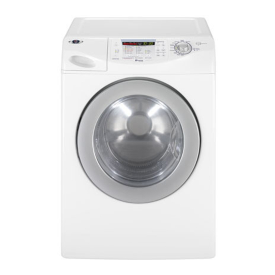
27” front load washer
Hide thumbs
Also See for Neptune MAH9700:
- Field advice (6 pages) ,
- Technical training manual (52 pages)
Advertisement
Quick Links
Advertisement

Related Manuals for Maytag Neptune MAH9700


Summary of Contents for Maytag Neptune MAH9700
- Page 1 Maytag Neptune 27” Front Load Washer © Maytag Technical Training Services 2005 L2005-004...
- Page 3 Kwantlen University Maytag Authorized Training Centers College 12666 72 Surrey, BC Hibbing Community College Canada V3W2M8 1515 East 25 Bay State School of Technology 604-599-2962 Hibbing, MN. 55746 225 Turnpike St 218-262-7231 Canton, MA. 02021 888-828-3434 Los Mendanos College 2700 East Leland Rd...
- Page 5 6700 & 8700 use four weights. Two attached to the front of outer tub, one behind the spinner pulley and one mounted to the right rear side of the outer tub Slide 3 Maytag Neptune 27” Front Load Washer MAH9700 This training presentation is based on the MAH9700.
- Page 6 Slide 4 Maytag Neptune Washer MAH9700 Dimensions Base Cycles Washer Width 27” Sanitary 151 Degrees F Washer Depth 30.75” Super Wash Washer Height 38” Normal Washer Weight 191 LBS Whites Pedestal/Riser (MAL1800AX*) 13” Wrinkle Control Features Colors Capacity (cu.ft) 3.81...
- Page 7 Slide 5 Note: The Power Point Presentation and Participant’s Guide for this training session were developed using prototype machines. There might be slight cosmetic differences between the product pictured and the current production units. Always refer to the Technical Data Sheet for detailed information for the product you are servicing.
- Page 8 Slide 8 The installation package contains the fill hoses, a combination wrench for removing the shipping bolts and adjusting the leveling legs, filler plugs and a drain hose bracket. Slide 9 Remove the four 10mm shipping bolts and spacers Slide 10 Save the shipping bolts and spacers and installation instruction in case of a future move.
- Page 9 Slide 11 Install the filler plugs supplied in the installation kit. Slide 12 Leg in Shipping Position Level the machine side to side and front to back Tighten Nut After leveling, make sure to tighten the locking nut against the base. Failure to do so will cause excessive vibration The washer must be installed on a sturdy floor and leveled.
-
Page 10: Enviro Plus
Slide 13 The 9700 washer timer features two additional cycles MAH 8700 Timer not found on the 8700; Sanitary and Enviro Plus MAH 9700 Timer The Sanitary cycle delays during the first wash to heat the wash water. A 900 Watt heating element located in the bottom of the outer tub is used to raise the water temperature to 151 degrees F. - Page 11 Slide 15 MAH8700 Spin Speeds 1100 RPM 800 RPM 600 RPM 400 RPM 0 RPM Slide 16 The 9700 has additional options available not found on the 8700. It also uses a cycle progression bar to indicate cycle position, the 8700 uses LED’s MAH 9700...
- Page 12 Slide 17 MAH9700 Spin Speeds 1200 RPM 1000 RPM 800 RPM 600 RPM 400 RPM 0 RPM Slide 18 ATC Control When ATC cold wash is selected, Heater turns on if the water temperature in the tub is below 60 degrees F. Heater turns off if the water temperature is above 70 degrees F or the time runs out for wash time.
- Page 13 Slide 19- Maytag Neptune MAH9700 Time Chart Maytag Neptune MAH9700 Time Chart M a y t a g N e p t u n e M A H 9 7 0 0 C y c l e S e q u e n c e T i m e ( m i n u t e ) W a t e r T e m p ( U n i t : D e g .
- Page 14 Slide 20 - Removing the Top Slide 21 Remove two 10mm screws Slide 22 The slot in the top panel slides around the base of the screw head securing the top to the cabinet...
- Page 15 Slide 23 - Component Identification Slide 24 Component Identification Vent hoses Harmonic Balance Assembly Reactor Dispenser Assembly Suspension Spring Water Level Switch Slide 25 Two hoses attached to the tub vent out the back. The vents are at different heights to promote air circulation through the tub and spinner.
- Page 16 Slide 26 Hot Valve Cold Valve Assembly Water Level Sensor- Pressure Switch Slide 27 - Slide 28 Pressure switch/Water level sensor The water sensor, usually referred to as a pressure switch communicates with the control circuit board via a frequency signal.
- Page 17 With an empty spinner, select Normal Wash and let the unit fill. Measure the depth of the water at the very back of the spinner at the six o’clock position. The water level should be approximately 3 ½ “ 3 ½” Water level intersects the 6 hole on the back of the spinner...
- Page 18 Reactor Slide 30 – Slide 31 Twist bracket Remove screw counterclockwise Remove screw and slide reactor out of bracket Slide 32 The reactor coil is wired in series with line internally in the control board. An open coil would result in a “dead”...
- Page 19 Slide 33 - Slide 34 Loosen 13mm nut and slide the EMI out of the bracket Mark wire locations for reinstallation Water Valves Slide 35 - Slide 36 The hot water valve and the 3-valve cold water assembly are secured with two screws...
- Page 20 Slide 37 The three valve cold water assembly supplies water for main fill, bleach and fabric softener dispense. The fabric softener and bleach dispense outlets have flow washers, the main fill does not Slide 38 The resistance of all four fill valves is the same, approximately 1130 OHMS...
- Page 21 Dispenser Slide 39 - Slide 40 Depress release and pull dispenser assembly out Slide 41 Remove the fill hoses, a diagram on the top of the dispenser shows correct routing Main Main Bleach Cold Wash...
- Page 22 Slide 42 Remove screw, lift dispenser and remove fill hose Notes...
- Page 23 Slide 43 Water flow through dispenser during Wash fill WASH FILL / COOLING / DRAIN (HEATING) WASHING Rotation of DISENTANGLE TOTAL Spinner COLD First minute of fill with no water in tub (Reset Level – 25.6 kHz) WATER WATER Valve #3 opens and cold water flows through path #3 to detergent V #1 compartment (Pre wash) V #3...
- Page 24 Slide 44 Water flow through dispenser during Rinse 1 fill RINSE 1 DISENTANGLE FILL / MIDTERM / FILLING TO DRAIN RINSE Rotation of SPIN REMOVE TOTAL Spinner SUDS WATER COLD WATER V #4 From NO water level (Reset Level) to the V #3 V #1 specified (final) water level...
- Page 25 Slide 45 Water flow through dispenser during Rinse 2 fill RINSE 2 FILL / DISENTANGLE MIDTERM DRAIN RINSE Rotation of / FILLING TO SPIN TOTAL Spinner REMOVE SUDS COLD WATER WATER V #3 V #4 V #1 From no water level (Reset Level) to sensing level (25.1kHz), Valves #1 &...
- Page 26 Removing Console Slide 46 - Slide 47 Remove five screws Lift the console, roll back and out Slide 48 Remove reactor wire harness from restraint...
- Page 27 Slide 49 Remove the red two wire reactor harness from the board. This will allow you to position the console to ease disassembly. Remove the remaining connectors Slide 50 Remove the 5 screws securing the circuit board to the console and lift off the board assembly.
- Page 28 Slide 51 The “power on” actuating lever and push button are replaceable items. To remove the lever, slide the shaft in either direction and lift out the opposite side. Release the locking tabs on the push button and remove Removing Front Panel Slide 52 - Slide 53 Locate the boot retainer spring...
- Page 29 Slide 54 Start at the two o’clock position and pull the gasket off the front panel lip. Push the gasket into the tub Slide 55 Remove 4 screws across the top of front panel Disconnect the wire Lift off the front panel connectors on the door switch...
- Page 30 Slide56 Counter Weights Fill Hose Heater Front Struts Removing the Boot Gasket Slide 57 - Slide58 Begin by removing the front panel. Locate the retainer clamp at the 12:00 o’clock position Loosen the retainer screw Remove the gasket retainer...
- Page 31 Slide 59 Pull off the old gasket Slide 60 Remove the tub weights to ease installation of the gasket Align the two index tabs on the gasket with the screws below the fill tube Install retainer and tighten clamp Work gasket onto tub lip...
- Page 32 Heating Element Slide 61 - Slide 62 900 Watt heating Element Thermistor leads Ground Heater Leads Slide 63 Loosen 10mm nut Remove element Thermistor Element is installed on top of the bracket Tightening the 10 mm nut expands the gasket...
- Page 33 Slide 64 Index Mark Fill Tube Motor Removal Slide 65 - Slide 66 Lift panel and pull bottom out and down Remove 2 screws...
- Page 34 Slide 67 Direct Drive Motor Slide 68 Loosen screw on vent hose clamp and Insert stop Remove the vent tube and rotate the spinner. Locate one of Use a tool with a rubber coated the three slots in the spinner. handle to prevent damage Insert a suitable tool to use as a stop.
- Page 35 Slide 69 Remove 19mm nut Torque Spec. 32-47 ft. lb. Slide 70 Grasp the rotor at the 9 and 3 o’clock position and pull The magnets make the removal of the rotor difficult...
- Page 36 Slide 71 Warning: Do not place fingers between rotor and tub when removing or installing rotor Warning: Do not place fingers between rotor and tub when removing or installing rotor Slide 72 Depress the release and remove connectors...
- Page 37 Slide 73 Remove the six 10mm bolts securing stator coil to the tub Slide 74 Stator Locating Pegs Rear Bearing and Spinner Shaft Drain pump Slide 75 -...
- Page 38 Slide 75 – Drain Pump Removal Slide 76 Remove hose clamp and drain hose from drain pump Remove tub hose from drain pump Slide 77 Unplug connector and remove 3 12mm bolts securing drain pump assembly to base and remove Slide 78 120 VAC 80 Watt motor Remove screw from bottom side...
-
Page 39: Removing The Tub
Removing the tub Slide 79 - Slide 80 Loosen hose clamp screw and remove the tub hose Slide 81 Remove the 13mm bolts securing the rear struts Left rear strut Torque Spec. 18-25 ft-lb. Right rear strut Slide 82 Rotate the struts up against the bottom of the tub to ease removal of the tub assembly The rear struts can be identified... - Page 40 Slide 83 Remove two 13mm bolts and roll weights off index posts Torque Spec. 11-22 ft. lb. Warning: Weights are heavy use caution when removing or installing Slide 84 Remove the wires from the heater element, thermistor and ground Slide 85 Remove the front struts and fold the struts up against the bottom of the tub...
- Page 41 Slide 86 1x12 - 32” long Insert a board or boards across the bottom of the washer frame to use as a support when removing Note: any dimension lumber can be the tub assembly used if it’s long and wide enough to support the tub Slide 87 Remove fill hose...
- Page 42 Slide 89 Prepare console back guard for removal Cut wire tie Remove pressure hose Unplug connector Remove ground wire Slide 90 Remove the left and right side vent hoses...
- Page 43 Slide 91 Begin with the suspension spring under the Dynamic Balance. Grasp the tub with one hand and the spring with the other. Lift and remove the spring from the slot in the frame Slide 92 Remove the spring on the opposite side and let tub Long End rest on board support...
- Page 44 Slide 93 Remove screws on back guard and cross member Lift support Remove back guard Slide 94 Grasp the front and rear of the tub and slide out. Use a blanket or rug to protect the floor...
- Page 45 Slide 95 Set the tub on the floor. Position 4” wood blocks or equivalent around the spinner shaft. Roll the tub to the upright position and rest it on the blocks Slide 96 Toque Spec. 6-11 ft-lb. Remove the 10mm screws on the perimeter of the tub...
- Page 46 Slide97 Separate the front and rear halves of the outer tub Slide98 There is a gasket between the tub halves...
- Page 47 Slide 99 A wave washer is installed between the spinner and seal Slide 100 Remove 1 screw and slide the baffle to release the mounting tabs from the spinner...
- Page 48 Slide 101 Maytag Neptune 8700 Front Load Washer Slide 102 Differences between the 8700 and 9700 Belt drive motor Weight added to right rear of outer tub Weight added to back of the outer tub behind pulley 2 less cycles, 1 less option, water temperature setting and spin speed...
- Page 49 Kwantlen University Maytag Authorized Training Centers College 12666 72 Surrey, BC Hibbing Community College Canada V3W2M8 1515 East 25 Bay State School of Technology 604-599-2962 Hibbing, MN. 55746 225 Turnpike St 218-262-7231 Canton, MA. 02021 888-828-3434 Los Mendanos College 2700 East Leland Rd...
- Page 52 Be Aware, Be Alert Always work safely. On the Job, On the Road, In the Home Every Time, All the Time...