Advertisement
Quick Links
AP633A Passive Infrared Detector Installation
Instructions
Description
The AP633A offers the detection of motion for infrared targets
in selectable ranges extending 40 feet (12.2m), 80 feet
(24.4m), and 200 feet (61.0m). The viewing angle selection
allows the installer to select and delete any portion of the
coverage pattern to customize the optical performance of the
unit. The mounting plate of the unit is equipped with precise
adjustment screws to allow the installer to alter the horizontal
viewing point as much as 2 degrees to the left or right, up or
down. Features include:
•
Step focus curtain
•
Calibrated sensitivity
•
Coverage up to 200-foot (61.0m) max.
•
12 different protection patterns
•
Precision step focus mirror optics
•
Form C contacts
Mounting tips
•
Do not mount the unit outdoors.
•
Do not block the viewing angle of the unit.
•
Mount the unit so that would-be intruders cross the pattern
of detection at a 90 degree angle.
•
Seal all openings and wire entries.
•
When mounting the unit on masonry surfaces, use an
appropriate moisture barrier.
•
Use of the vertical screw adjustment may reduce the unit's
range.
•
Avoid these sources of disturbance:
•
Sunlight or vehicle headlights shining directly onto the
unit.
•
Heat sources or mobiles in the field of view.
•
Strong air drafts blowing onto the unit.
•
Animals in the field of view.
•
Insects in the housing or on the face of the unit.
•
Rapid temperature changes in the field of view.
•
Very strong sources of RF energy and induction of
electrical noise.
P/N 1036522 • REV C • 19JUN12
Installing the unit
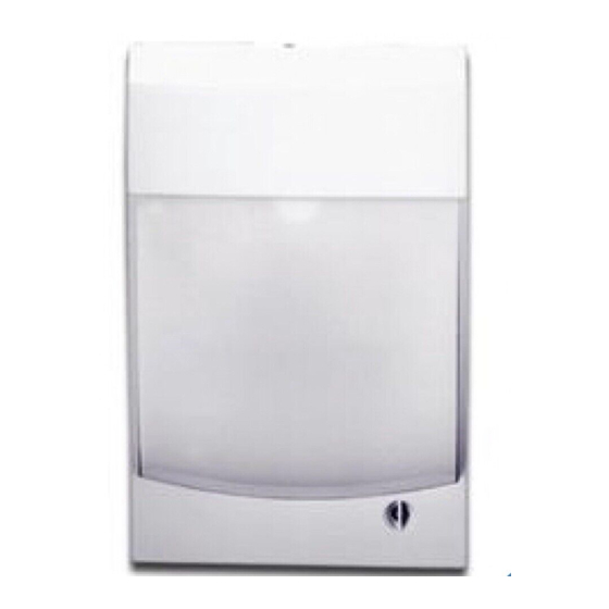
1.
Loosen the screw at the bottom of the unit; then remove
the front housing (Figure 1 below).
Caution:
You must be free of static electricity before handling
sensor circuit boards. Touch a grounded, bare metal surface
before touching circuit boards or wear a grounding strap.
Figure 1: AP633A
2.
Pull down on the plastic locking tab at the base of the
circuit board to remove the mirror/circuit board assembly.
See Figure 2 on page 2.
3.
Remove the appropriate wiring knockouts and pull the
cable through the entries. See Figure 3 on page 2.
4.
Level the backplate to the wall leaving a 1/2 inch
clearance space above the unit. For flat-wall mounting,
use the four mounting holes. For corner mounting
applications remove the mounting knockouts located in
each corner. See Figure 3 on page 2. Insert 8-32 x 2 inch
screws. Tighten until secure, but be careful not to over-
tighten the backplate as you may need to adjust the
viewing angle after walk testing.
5.
Replace the mirror/circuit board assembly then make wire
connections. See Figure 4 on page 2.
1
Advertisement

Related Manuals for Interlogix AP633A


Summary of Contents for Interlogix AP633A
- Page 1 Instructions Description Installing the unit The AP633A offers the detection of motion for infrared targets Loosen the screw at the bottom of the unit; then remove in selectable ranges extending 40 feet (12.2m), 80 feet the front housing (Figure 1 below).
- Page 2 Jumper D Jumper B (LED) (Test) Tamper Terminals Viewing Angle Adjustment Setting the sensitivity Select the sensitivity setting that best meets the needs of a given application by changing Jumper A (see Figure 5 on AP633A Passive Infrared Detector Installation Instructions...
- Page 3 Test - Off 3. After identifying each zone location, return the unit to normal mode by inserting Jumper B on only one pin so that the two pins are not connected. AP633A Passive Infrared Detector Installation Instructions...
-
Page 4: Specifications
Dimensions 6.3" x 4.1" x 3.0" (16.0cm x 10.4cm x 7.6cm) www.utcfireandsecurity.com www.interlogix.com For customer support, see www.interlogix.com/customer- support Regulatory information Copyright © 2012 UTC Fire & Security. All rights reserved. Listings UL 639 AP633A Passive Infrared Detector Installation Instructions...