Table of Contents
Advertisement
Advertisement
Table of Contents

Related Manuals for Midea MFJ-24ARN1-QB8


Summary of Contents for Midea MFJ-24ARN1-QB8
- Page 1 Floor Standing Type Air Conditioner Model: MFJ-24ARN1-QB8 MFJ-48ARN1-RB6...
-
Page 2: Table Of Contents
Display panel ....................... 6 Refrigerant cycle diagram ................7 Cooling only ........................7 Heat pump mode ......................7 PCB drawing & wiring diagram ..............8 MFJ-24ARN1-QB8 ......................8 MFJ-48ARN1-RB6 ......................9 Installation detail ................... 10 Installation place ....................... 10 Installing ........................11 Refrigerant pipe connecting ..................13... -
Page 3: Safety Precautions
Safety Precautions Safety Precautions 1.1 Precaution To prevent injury to the user or other people and property damage, the following instructions must be followed. Incorrect operation due to ignoring instruction will cause harm or damage. Before service unit, be sure to read this service manual at first. 1.2 Installation For electrical work, contact the dealer, seller, a qualified electrician, or an Authorized service center. - Page 4 Safety Precautions Do not touch the metal parts of the product when removing the air filter. They are very sharp. Do not step on pr put anything on the product. (outdoor units) Always insert the filter securely. Clean the filter every two weeks or more often if necessary. Do not insert hands or other object through air inlet or outlet while the product is operated.
-
Page 5: Out Dimensions
Outer Dimensions Out Dimensions 2.1 Indoor Unit Dimension Width Height Depth Mode (mm) (mm) (mm) 1700 1825... -
Page 6: Outdoor Unit
Outer Dimensions 2.2 Outdoor Unit Dimension W idth Height Depth Mode (mm) (mm) (mm) (mm) (mm) Dimension W idth Height Depth Mode (mm) (mm) (mm) (mm) (mm) 1245... -
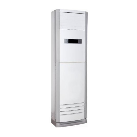
Page 7: External View And Display
External view and display External view and display 3.1 External view Outd oor unit Indoor unit Drain pipe, vent pip e Air outlet Connection cable Operation panel Connection pipe Horizo ntal airflow control louver Refrigerant pipe po rt Vertic al airflow control louver Air outlet Remote controller holder(on some models) Air inl et(2 sides) -
Page 8: Display Panel
External view and display 3.2 Display panel Room Te mp/Set Temp /Set Tim er display AUX ILI ARY FU N CTION A DJU ST T2 T3 T4 auto ON/OF F M ODE M ODE LOCK TE ST R U N N ING A DJU ST S PEED Fan speed... -
Page 9: Refrigerant Cycle Diagram
Refrigerant cycle diagram Refrigerant cycle diagram 4.1 Cooling only 4.2 Heat pump mode... -
Page 10: Pcb Drawing & Wiring Diagram
PCB drawing & Wiring diagram PCB drawing & wiring diagram 5.1 MFJ-24ARN1-QB8 Indoor unit Outdoor unit... -
Page 11: Mfj-48Arn1-Rb6
PCB drawing & Wiring diagram 5.2 MFJ-48ARN1-RB6 Indoor unit Outdoor unit... -
Page 12: Installation Detail
Installation detail Installation detail 6.1 Installation place 6.1.1 Indoor Unit A place which provides the spaces around the indoor unit as required above in the diagram. A place where is no obstacle near the inlet and outlet area. A place which can bear the weight of the indoor unit. A place which allows the air filter to be removed downward. -
Page 13: Installing
Installation detail 6.1.2.2 If the outdoor unit is to be installed on a roof or where no constructions are around, you should avoid hard wind blows directly to the air outlet, because it may cause trouble for air-flow shortage. 6.1.2.3 Reserve enough space for installation, maintenance and unit-functioning. Remove as many obstacles as possible nearby. - Page 14 Installation detail 6.2.3 Take the Pipe Clip off before connecting the pipes and wiring; fit it when these finished. Use accessories 4 and 9 to connect the pipes/wires on both sides and back side. Pipe/wire-hole positions on both sides Drain Pipe Refrigerant Pipe Refrigerant/drain Wiring...
-
Page 15: Refrigerant Pipe Connecting
Installation detail Make a concrete basement to the unit by the above references. 6.3 Refrigerant pipe connecting 6.3.1 Pipe length and the elevation The correct refrigerant quantity filled in the 5-meter-long pipe of the outdoor unit is marked on the Product Data Plate. If you have to use longer pipe for every meter plus pipe, the refrigerant should be added according to the following calculation. - Page 16 Installation detail vacuum the indoor unit through the maintenance port on the cut-off valves, or open the high-pressure valve, and exhaust the air through the maintenance port on the low-pressure valve(closed). It will take about ten seconds. Then screw tightly the maintenance port. (When supplement the refrigerant, fill through the maintenance port of the low-pressure valves on the outdoor unit ).
-
Page 17: Drain Pipe Of The Indoor Unit
Installation detail f. Turn the stem of the packed valve B about 45 counterclockwise for 6~7 seconds after the gas coming out, then tighten the flare nut again. Make sure the pressure display in the pressure indicator is a little higher than the atmosphere pressure. g. -
Page 18: Test Operation
Installation detail (Wiring size: 2.5mm ) ≥ (Wiring size: 2.5mm ) ≥ Note: Some models is equipped with a cord having a plug, So a wall outlet shall be properly installed. 6.6 Test operation Perform test operation after completing gas leak and electrical safety check. The test operation time should last more than 30 minutes. -
Page 19: Electronic Function
Electronic function Electronic function 7.1 Performance Index Item Index Applicable Voltage Range 185-253V, 342-418V A/C Frequency 50Hz Working environment temperature -7° C- +45° C 7.2 Main data Introduction Ts : Set temperature, T1 : Room temperature T2: Evaporator pipe temperature 7.3 Operation Modes and Functions 7.3.1 Manual Operation 7.3.2 Heating Mode... - Page 20 Electronic function T2<20° C 7.3.3 Defrost (only available to heating mode) 7.3.3.1 Defrosting Conditions Starting Of Defrosting Condition (meet one of the following is ok): (1)Accumulated compressor operating time when temperature of outdoor heat exchanger coil T3 is below -2° C reaches up to over 46 minutes.(When T3 is over 20° C, calculate time again.) (2) Under evaporator high temperature protection, the accumulated time when outdoor fan motor is off and compressor is on reaches up to over 90 minutes .(When T3 is over 20°...
-
Page 21: Other Functions
Electronic function 7.3.6 Auto Mode 7.3.6.1 Under auto mode, the indoor fan is set to be auto. 7.3.6.2 When entering auto mode, the heating, fan only or cooling operation will be automatically chosen according to the room temperature T1 and the set temperature Ts. -
Page 22: Characteristic Of Temperature Sensor
Characteristic of temperature sensor Characteristic of temperature sensor Temp. ℃ Resistance K Temp. ℃ Resistance K Temp. ℃ Resistance K 62.2756 14.6181 4.3874 58.7079 13.918 4.2126 56.3694 13.2631 4.0459 52.2438 12.6431 3.8867 49.3161 12.0561 3.7348 46.5725 11.5 3.5896 10.9731 3.451 41.5878 10.4736 3.3185... -
Page 23: Trouble Shooting
Exploded view & spare-part Trouble shooting 9.1 Protective Function 9.1.1 3-minute delay for the compressor start-up At the beginning of energizing or after the stop of the compressor, 3-minute delay will be needed to start the compressor. When switching over between cooling/heating mode, the compressor stops automatically. 9.1.2 Evaporator protection against high temperature 9.1.2.1 Only available under heating mode. -
Page 24: Troubles And Solutions
Exploded view & spare-part The condenser temperature sensor T3 is open or short Protection of outdoor unit 9.2.1 LEDs for the indication of outdoor trouble In normal operation, LEDs emit no light and they will flash at a frequency of 5 Hz when trouble occurs. - Page 25 Exploded view & spare-part Number Display code Problem What to do E1 E2 E3 E4 Temperature Sensor is off or short-circuit. Contact service people Outdoor unit protection Contact service people Electrostatic dust collection Contact service people The temperature of the evaporator of indoor Turn off the unit, clean the air unit is too low or high (For the protection filter, then restart the unit.
- Page 26 Exploded view & spare-part Specification Model Model Model Model MFJ-24ARN1-QB8 MFJ-48ARN1-RB6 Factory Code Factory Code Factory Code Factory Code 2T004330T031 2T004370T020 Electrical Data Electrical Data Electrical Data Electrical Data Power supply Ph-V-Hz 1φ,220-240V,50HZ 3φ,380-420V,50HZ Capacity Cooling/Heating Btu/h 24000/27000+7200 46000/49000+12000 Power consumption...
- Page 27 Exploded view & spare-part Brand Welling Welling Input Capacitor 5UF/450V 6.5UF/450V Speed(high/low) r/min 575/540/440 600/550/480 Model YDK100-6D YDK65-6F/YDK65-6 Brand Welling Welling Outdoor Input 156/148 Capacitor 5UF/450V 3.5UF/450V Speed r/min...