Table of Contents
Advertisement
Revision O: 2103, Content updated.
Table of Contents
1.
Precaution
2.
Part Names And Functions
3.
4.
5.
6.
7.
Fan Curves
8.
Air Velocity Distributions
9.
11. Accessories
Installation MUST conform with local building codes or, in the absence of local codes, with the
National Electrical Code NFPA70/ANSI C1-1993 or current edition and Canadian Electrical
Code Part1 CSA C.22.1.
The information contained in the manual is intended for use by a qualified service technician
familiar with safety procedures and equipped with the proper tools and test instruments
Installation or repairs made by unqualified persons can result in hazards to you and others.
Failure to carefully read and follow all instructions in this manual can result in equipment
malfunction, property damage, personal injury and/or death.
This service is only for service engineer to use.
Light commercial MONO 3D Air
Conditioner
SERVICE MANUAL
Model Numbers:
MCA3U-09HRFN1-M(C); MCA3U-12HRFN1-M(C); MCA3U-18HRFN1-M(C);
MFAU-12HRFN1-M(C); MCD-24HRFN1-M(C); MCD-36HRFN1-M(C);
MCD-48HRFN1-M(D); MUEU-18HRFN1-M(C); MUEU-24HRFN1-M(C); MUE-36HRFN1-M(C);
MUE-48HRFN1-M(C); MUE-60HRFN1-MW; MTIU-09HWFN1-M, MTIU-12HWFN1-M;
MTIU-18HWFN1-M; MTIU-24HWFN1-M; MTI-36HWFN1-M; MTI-48HWFN1-M;
MHG-60HWFN1-MW;
MCD1-24HRFN1-MT0W(GA)
MOB30-09HFN1-MX0W; MOB01-09HFN1-MW0W; MOB30-12HFN1-MV0W;
MOB01-12HFN1-MV0W; MOCA30-18HFN1-MT0W; MOCA01-18HFN1-MT0W;
MOD30-24HFN1-MT0W; MOD01-23HFN1-MT0W; MOBA30-09HFN1-MT0W;
MOB30-12HFN1-MT0W; MOCA31-18HFN1-MT0W; MOD31-24HFN1-MT0W;
MOD30U-36HFN1-M; MOE30U-48HFN1-M; MOE30U-60HFN1-M; MOE30U-36HFN1-M-[X]
MOE30U-48HFN1-M-[X]; MOD30U-36HFN1-MP0; MOE30U-48HFN1-MP0
MOX230-09HFN1-MW5W; MOX330-09HFN1-MY5W; MOX230-12HFN1-MV5W;
MOX330-12HFN1-MW5W, MOX430-17HFN1-MT0W, MOD30-24HFN1-MU0W,
MOD33-24HFN1-MT0W
Mono DC
Advertisement
Table of Contents

Related Manuals for Midea MCA3U-09HRFN1-M(C)


Summary of Contents for Midea MCA3U-09HRFN1-M(C)
- Page 1 Light commercial MONO 3D Air Conditioner Mono DC SERVICE MANUAL Revision O: 2103, Content updated. Table of Contents Model Numbers: Precaution Indoor Unit: Part Names And Functions MCA3U-09HRFN1-M(C); MCA3U-12HRFN1-M(C); MCA3U-18HRFN1-M(C); Dimension MFAU-12HRFN1-M(C); MCD-24HRFN1-M(C); MCD-36HRFN1-M(C); Service space MCD-48HRFN1-M(D); MUEU-18HRFN1-M(C); MUEU-24HRFN1-M(C); MUE-36HRFN1-M(C); Refrigerant Cycle Diagram MUE-48HRFN1-M(C);...
- Page 2 CONTENTS 1. Precaution ..............................1 1.1 Safety Precaution .......................... 1 1.2 Warning ............................1 2. Part Names and Features..........................4 2.1 Model Names of Indoor/Outdoor units ..................4 2.2 Part names of Indoor/Outdoor units ....................5 2.3 Features ............................10 3.
- Page 3 16. Electronic Function ..........................181 16.1 Abbreviation ..........................181 16.2 Display function ........................181 16.3 Main Protection ........................181 16.4 Operation Modes and Functions ..................... 183 17. Troubleshooting ............................. 196 17.1 Indoor Unit Error Display ......................197 17.2 Error Display on Two Way Communication Wired Controller ..........199 17.3 Outdoor unit error display ......................
- Page 4 Be caution when unpacking and installing the product. 1. Precaution Sharp edges could cause injury, be especially careful of the case edges and the fins on the 1.1 Safety Precaution condenser and evaporator. For installation, always contact the To prevent injury to the user or other ...
- Page 5 If strange sounds or smoke comes Install the drain hose to ensure that from product, turn the breaker off or water is drained away properly. disconnect the power supply cable. A bad connection may cause water leakage. There is risk of electric shock or fire. Keep level even when installing the ...
- Page 6 Do not insert hands or other objects through air inlet or outlet while the product is operated. Do not drink the water drained from the product. Use a firm stool or ladder when cleaning or maintaining the product. Be careful and avoid personal injury.
- Page 7 2. Part Names and Features 2.1 Model Names of Indoor/Outdoor units Outdoor units Series Capacity Indoor units MOB30-09HFN1-MX0W; Console MFAU-09HRFN1-M(C) MOB01-09HFN1-MW0W; MOBA30-09HFN1-MT0W MOB30-09HFN1-MX0W; Cassette MCA3U-09HRFN1-M(C) MOB01-09HFN1-MW0W; MOBA30-09HFN1-MT0W A6 Duct MTIU-09HWFN1-M MOX230-09HFN1-MW5W; MOX330-09HFN1-MY5W MOB30-12HFN1-MV0W; Cassette MCA3U-12HRFN1-M(C) MOB01-12HFN1-MV0W; Console MFAU-12HRFN1-M(C) MOB30-12HFN1-MT0W; MOX230-12HFN1-MV5W; A6 Duct MTIU-12HWFN1-M MOX330-12HFN1-MW5W...
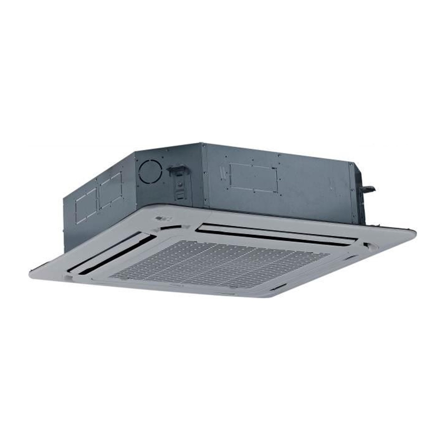
- Page 8 2.2 Part names of Indoor/Outdoor units Cassette Units...
- Page 9 New Cassette Units A6 Duct Units...
- Page 10 Console Units...
- Page 11 Ceiling-floor Units...
- Page 12 HESP DUCT Units...
- Page 13 2.3 Features 2.3.1 Cassette Units 2.3.1.1 Lower Noise Optimize air channel system design to ensure the maximum quietness and comfort. Noise max down 6dB. 2.3.1.2 Turbo Mode (Optional) Turbo function can boost cooling or heating speed in a short period, and makes the room cool ...
- Page 14 Compared with infrared remote controller, wired controller can be fixed on the wall and avoid mislaying. It's mainly used for commercial zone and makes air conditioner control more convenient. 2.3.1.6 Build-in Drain Pump The drain pump can lift the condensing water up to 750mm upmost. ...
- Page 15 2.3.2 Console Units 2.3.2.1. Modern and Elegant Appearance The simple and stylish designs can nicely harmonies with your living space. 2.3.2.2. Two Air-outlet Ways Cooling mode Quick Cooling To maintain room temp Air outlet from top and bottom to make quick cooling ------When the A/C is just switched on, or ...
- Page 16 2.3.2.3. Four Air Inlets 2.3.2.4. Low Noise DC indoor fan motor, which has five speeds. Low noise and energy saving. Advanced centrifugal fan technology makes a fast airflow and reduces the indoor noise. ...
- Page 17 2.3.3 Ceiling-floor Units 2.3.3.1 Two-way Installation The rounded design of the ceiling and floor type air conditioner allows either ceiling or floor-level installation. Ceiling installation saves room space, while floor installation helps prevent the loss of warm air. 2.3.3.2 Brief Design Brief design that is suitable for any interior will not only give you cooling and heating performance ...
- Page 18 2.3.3.7 Outside Water Pump for Optional When Ceiling Installation.
- Page 19 2.3.4 A6 Duct Units Higher Static Pressure 2.3.4.1. As a ducted air conditioner with medium static pressure, it has the widest static pressure range. The maximum static pressure reaches 160Pa Slim Design 2.3.4.2. The industry Lowest height is designed to be fitted into tight roof spaces. ...
- Page 20 A6 duct uses two wires without polarity connection way, which almost has no mistake during the installation. Easy Clean 2.3.4.5. With a larger window design, once the motor and the blower wheels have been detached, heat exchanger and water receiver tray in behind can be seen very clearly. Dust can be easily removed from the inside by vacuum 2.3.4.6.
- Page 21 2.3.4.7. Drain pump (Optional) Built-in drain pump can lift the water to 750mm upmost, which widens the drainage piping range. ...
- Page 22 2.3.5 HESP DUCT Units 2.3.5.1 High static pressure design Max static pressure of indoor unit is 200Pa. The longest distance of air supply is 40m, the max height of air supply is 6.5m. Specially recommended for spacious and large rooms like large stores and factories. ...
- Page 23 3. Dimension 3.1 Indoor Unit Cassette Units(9K, 12K, 18K) Liquid side Gas side Body Drain hole Wiring connection port ( for Service ) E-parts box 4-Screw hole (for install panel) 4-install hanger Drain pipe Fresh air intake Wiring connection port Panel...
- Page 24 Cassette Units (24K, 36K, 48K) 92 92 Fresh air intake 4-install hanger Body Gas side Liquid side Wiring connection port E-parts box Service hole for Test mouth & Test cover draining pump Drain hole 92 92 92 92 Panel Capacity (Btu/h) Unit inch 6.30...
- Page 25 New Cassette Units(24K, 36K, 48K) Capacity (Btu/h) Unit inch 3.15 8.03 1.97 inch 3.64 9.65 2.36 inch 3.64 11.30 2.36...
- Page 26 Console Units Hanging arm 16 Drain pipe Unit: mm...
- Page 27 Ceiling-floor Units (18K-60K) Wiring connection port Drain discharge port Fresh air intake Refrigerant pipe hole Hanging arm Capacity (Btu/h) Unit 1068 18K / 24K inch 42.05 26.57 9.25 38.70 1285 1200 inch 50.59 26.57 9.25 47.24 1650 1565 48K/60K inch 64.96 26.57 9.25...
- Page 28 A6 Duct Units Model unit (KBtu/h) 9/12 inch 27.6 19.9 17.7 21.1 23.6 29.2 14.2 inch 34.6 26.5 23.6 27.8 30.8 36.2 20.0 1100 1001 1140 inch 43.3 30.5 27.6 36.5 39.4 44.9 23.5 1360 1186 1261 1400 inch 53.5 30.5 27.6 46.7...
- Page 29 9/12K with external condensate pump(optional)
- Page 30 18K with external condensate pump(optional)
- Page 31 MHG-60HWFN1-MW (suspension position) 2-Φ3.2 Φ5 NOTE:16 groups all around(the same of the air inlet flange)
- Page 32 3.2 Outdoor Unit Note: The above drawing is only for reference. The appearance of your units may be different. Model unit MOBA30-09HFN1-MT0W inch 30.3 11.8 21.9 33.1 19.2 11.7 MOB30-09HFN1-MX0W MOB30-12HFN1-MV0W MOB30-12HFN1-MT0W MOB01-09HFN1-MW0W inch 31.5 13.1 21.8 34.3 20.2 13.4 MOB01-12HFN1-MV0W MOCA01-18HFN1-MT0W MOCA30-18HFN1-MT0W...
- Page 33 Model Unit MOE30U-36HFN1-M-[X] 1333 1045 MOE30U-48HFN1-M MOE30U-48HFN1-M-[X] inch 37.5 16.3 52.5 41.1 25.0 15.9 MOE30U-48HFN1-MP0 MOE30U-60HFN1-M...
- Page 34 MOX230-09HFN1-MW5W, MOX230-12HFN1-MV5W...
- Page 35 MOX330-09HFN1-MY5W, MOX330-12HFN1-MW5W...
- Page 36 MOX430-17HFN1-MT0W...
- Page 37 4. Service Space 4.1 Indoor Unit A6 Duct Units Ensure enough space required for installation and maintenance. 200mm(7.87in) or more 300mm(11.81in) or more 600mmx600mm/23.62inx23.62in Check orifice All the indoor units reserve the hole to connect the fresh air pipe. The hole size as following Cassette Units Unit: mm...
- Page 38 New Cassette Units Capacity (kBtu/h) A(mm/inch) H(mm/inch) B(mm/inch) 204/8.03 >230/9.06 245/9.65 >271/10.7 900/35.4 287/11.3 >313/12.3...
- Page 39 Console Units Ceiling-floor Units...
- Page 40 HESP DUCT 500mm or more 600mm or more Indoor unit Maintenance and repair space 600mmx600mm 4.2 Outdoor Unit (Wall or obstacle) More than 30cm(11.81in) Air inlet More than 60cm More than 30cm (23.62in) (11.81in) Maintain channel More than 60cm Air inlet (23.62in) Air outlet More than 200cm(78.74in)
- Page 41 5. Refrigerant Cycle Diagram MOCA30-18HFN1-MT0W, MOCA01-18HFN1-MT0W, MOD30-24HFN1-MT0W, MOD01-23HFN1-MT0W, MOD31-24HFN1-MT0W, MOX330-09HFN1-MY5W, MOX330-12HFN1-MW5W INDOOR OUTDOOR Electronic CAPILIARY TUBE expansion valve LIQUID SIDE 2-WAY VALVE T3 Condenser temp. sensor HEAT EXCHANGE (EVAPORATOR) HEAT T4 Ambient T1 Room temp. EXCHANGE temp. sensor sensor (CONDENSER) T2 Evaporator temp.
- Page 42 MOB30-09HFN1-MX0W, MOB01-09HFN1-MW0W, MOB30-12HFN1-MV0W, MOB01-12HFN1-MV0W MOBA30-09HFN1-MT0W, MOB30-12HFN1-MT0W, MOCA31-18HFN1-MT0W, MOX230-09HFN1-MW5W, MOX230-12HFN1-MV5W INDOOR OUTDOOR Electronic CAPILIARY TUBE expansion valve LIQUID SIDE 2-WAY VALVE T3 Condenser temp. sensor HEAT EXCHANGE (EVAPORATOR) HEAT T4 Ambient T1 Room temp. EXCHANGE temp. sensor sensor (CONDENSER) T2 Evaporator temp.
- Page 43 MOE30U-36HFN1-M-[X], MOE30U-48HFN1-M-[X] INDOOR OUTDOOR Plate heat LIQUID SIDE exchanger Throttle orifice Check Valve 2-WAY VALVE T3 Condenser temp. sensor HEAT EXCHANGE HEAT (EVAPORATOR) T4 Ambient T1 Room temp. EXCHANGE T2 Evaporator temp. sensor sensor (CONDENSER) temp. sensor middle T2B Evaporator temp.
- Page 44 6. Wiring Diagram 6.1 Indoor Unit MCA3U-09HRFN1-M(C), MCA3U-12HRFN1-M(C), MCA3U-18HRFN1-M(C),MCD-24HRFN1-M(C)
- Page 45 MFAU-09HRFN1-M(C), MFAU-12HRFN1-M(C) MCD-36HRFN1-M(C), MCD-48HRFN1-M(D)
- Page 46 MCD1-24HRFN1-MT0W(GA)
- Page 47 MUEU-18HRFN1-M(C), MUEU-24HRFN1-M(C) MUE-36HRFN1-M(C)
- Page 48 MUE-48HRFN1-M(C) MUE-60HRFN1-MW...
- Page 49 MUE-36HRFN1-M(C),MUE-48HRFN1-M(C) MTIU-09HWFN1-M, MTIU-12HWFN1-M, MTIU-18HWFN1-M, MTIU-24HWFN1-M...
- Page 50 MTI-36HWFN1-M , MTI-48HWFN1-M, MHG-60HWFN1-MW 6.1.1 Some connectors introduce: MCA3U-09HRFN1-M(C), MCA3U-12HRFN1-M(C), MCA3U-18HRFN1-M(C),MCD-24HRFN1-M(C), MCD-36HRFN1-M(C), MCD-48HRFN1-M(D), MCD1-24HRFN1-MT0W(GA) A For remote control (ON-OFF) terminal port CN23 and short connector of JR6 1. Remove the short connector of JR6 when you use ON-OFF function; 2. When remote switch off (OPEN), the unit would be off; 3.
- Page 51 B For ALARM terminal port CN33 1. Provide the terminal port to connect ALARM, but no voltage of the terminal port , the power from the ALARM system (not from the unit ) 2. Although design voltage can support higher voltage, but we strongly ask you connect the power less than 24V, current less than 0.5A 3.
- Page 52 4. The new fresh motor will be worked when the indoor fan motor work ;when the indoor fan motor stops , the new fresh motor would be stopped ; 5. When the unit enter force cooling mode or capacity testing mode, the fresh motor isn’t work . MUEU-18HRFN1-M(C), MUEU-24HRFN1-M(C), MUE-36HRFN1-M(C), MUE-48HRFN1-M(C), MUE-60HRFN1-MW A For remote control (ON-OFF) terminal port CN23...
- Page 53 B For ALARM terminal port CN33 1. Provide the terminal port to connect ALARM, but no voltage of the terminal port , the power from the ALARM system (not from the unit ) 2. Although design voltage can support higher voltage, but we strongly ask you connect the power less than 24V, current less than 0.5A 3.
- Page 54 1. Connect the fan motor to the port, no need care L/N of the motor; 2. The output voltage is the power supply; 3. The fresh motor cannot excess 200W or 1A, follow the smaller one; 4. The new fresh motor will be worked when the indoor fan motor work ;when the indoor fan motor stops, the new fresh motor would be stopped;...
- Page 55 MTIU-09HWFN1-M, MTIU-12HWFN1-M, MTIU-18HWFN1-M, MTIU-24HWFN1-M, MTI-36HWFN1-M , MTI-48HWFN1-M, MHG-60HWFN1-MW A. For new fresh motor terminal port (also for Anion generator) CN43: 1. Connect the fan motor to the port, no need care L/N of the motor; 2. The output voltage is the power supply; 3.
- Page 56 B For ALARM terminal port CN33 1. Provide the terminal port to connect ALARM, but no voltage of the terminal port, the power from the ALARM system (not from the unit ) 2. Although design voltage can support higher voltage, but we strongly ask you connect the power less than 24V, current less than 0.5A 3.
- Page 57 6.1.2 Micro-Switch Introduce: MCA3U-09HRFN1-M(C), MCA3U-12HRFN1-M(C), MCA3U-18HRFN1-M(C),MCD-24HRFN1-M(C) A. Micro-switch SW1 is for selection of indoor fan stop temperature (TEL0) when it is in anti-cold wind action in heating mode. Range: 24 C, 15 C, 8 C, according to EEROM setting (reserved for special customizing). Setting fan speed TEL0+16 TEL0+14...
- Page 58 Range: Active, inactive D. Micro-switch SW5 is for setting mode priority of multi connection. Range: Heat, cool. E.Micro-switch SW6 is for selection of temperature compensation in heating mode. This helps to reduce the real temperature difference between ceiling and floor so that the unit could run properly. If the height of installation is lower, smaller value could be chosen.
- Page 59 MCD1-24HRFN1-MT0W(GA) A. Micro-switch SW1 is for selection of indoor fan stop temperature (TEL0) when it is in anti-cold wind action in heating mode. Range: 24 C, 15 C, 8 C, according to EEROM setting (reserved for special customizing). B. Micro-switch SW2/SW2-1 is for selection of indoor FAN ACTION if room temperature reaches the setpoint and the compressor stops.
- Page 60 C. Micro-switch SW2-2 is for selection of Breezeless function. Range: OFF, ON. D. Micro-switch SW3 is for selection of auto-restart function. Range: Active, inactive E.Micro-switch SW6 is for selection of temperature compensation in heating mode. This helps to reduce the real temperature difference between ceiling and floor so that the unit could run properly. If the height of installation is lower, smaller value could be chosen.
- Page 61 G. Micro-switch SW8 is for setting the master or slave unit when the unit is in twin connection. Range: Master no slave (Normal 1 drive 1 connection), Master (2 positions without difference), Slave H.Micro-switch S1 and dial-switch S2 are for address setting when you want to control this unit by a central controller.
- Page 62 MFAU-09HRFN1-M(C), MFAU-12HRFN1-M(C) A. Micro-switch SW1 is for selection of auto-restart function. Range: Active, inactive. B. Take off the panel, you can see the switch SW101 which is used for selecting both air outlets or upper air outlet only. C.Micro-switch SW102 is for selection of temperature compensation in heating mode. This helps to reduce the real temperature difference between ceiling and floor so that the unit could run properly.
- Page 63 MCD-36HRFN1-M(C), MCD-48HRFN1-M(D) A. Micro-switch SW1 is for selection of indoor fan stop temperature (TEL0) when it is in anti-cold wind action in heating mode. Range: 24 C, 15 C, 8 C, according to EEROM setting (reserved for special customizing). TEL0+16 Setting fan speed TEL0+14 TEL0+12...
- Page 64 D. Micro-switch SW5 is for setting the master or slave unit when the unit is in twin connection. Range: Master no slave (Normal 1 drive 1 connection), Master (2 positions without difference), Slave E.Micro-switch SW6 is for selection of temperature compensation in heating mode. This helps to reduce the real temperature difference between ceiling and floor so that the unit could run properly.
- Page 65 G. Dial-switch ENC1: The indoor PCB is universal designed for whole series units from 18K to 55K. This ENC1 setting will tell the main program what size the unit is. NOTE: Usually there is glue on it because the switch position cannot be changed at random unless you want to use this PCB as a spare part to use in another unit.
- Page 66 For MUEU-18HRFN1-M(C): B. Micro-switch SW2 is for selection of indoor FAN ACTION if room temperature reaches the setpoint and the compressor stops. Range: OFF (in 127s), Keep running. C. Micro-switch SW3 is for selection of auto-restart function. Range: Active, inactive D.
- Page 67 E.Micro-switch SW6 is for selection of temperature compensation in heating mode. This helps to reduce the real temperature difference between ceiling and floor so that the unit could run properly. If the unit is on-floor installed, 0 should be chosen. Range: 0 C, 2 C, 4...
- Page 68 B. Micro-switch SW2 is for selection of indoor FAN ACTION if room temperature reaches the setpoint and the compressor stops. Range: OFF (in 127s), Keep running. C. Micro-switch SW3 is for selection of auto-restart function. Range: Active, inactive D. Micro-switch SW4 is for selection of quantity of fan motors. Same as size selection switch, this switch is for making the PCB suitable for all series units.
- Page 69 Range: Single Fan, Double Fan E.Micro-switch SW6 is for selection of temperature compensation in heating mode. This helps to reduce the real temperature difference between ceiling and floor so that the unit could run properly. If the unit is on-floor installed, 0 should be chosen. Range: 0 C, 2 C, 4...
- Page 70 MUE-60HRFN1-MW A. Micro-switch SW1 is for selection of indoor fan stop temperature (TEL0) when it is in anti-cold wind action in heating mode. Range: 24 C, 15 C, 8 C , According to EEROM setting (reserved for special customizing). B. Micro-switch SW3 is for selection of auto-restart function. Range: Active, inactive C.
- Page 71 D.Micro-switch SW6 is for selection of temperature compensation in heating mode. This helps to reduce the real temperature difference between ceiling and floor so that the unit could run properly. If the unit is on-floor installed, 0 should be chosen. Range: 0 C, 2 C, 4...
- Page 72 MTIU-09HWFN1-M, MTIU-12HWFN1-M, MTIU-18HWFN1-M, MTIU-24HWFN1-M A. Micro-switch SW1 is for selection of indoor fan stop temperature (TEL0) when it is in anti-cold wind action in heating mode. Range: 24 C, 15 C, 8 C, according to EEROM setting (reserved for special customizing). B.
- Page 73 of installation is lower, smaller value could be chosen. Range: 6 C, 4 C, 2 C, E function (reserved for special customizing) D. Micro-switch S1 and dial-switch S2 are for address setting when you want to control this unit by a central controller.
- Page 74 B. Micro-switch SW3 is for selection of auto-restart function. Range: Active, inactive C. Micro-switch SW5 is for setting the master or slave unit when the unit is in twin connection. Range: Master no slave (Normal 1 drive 1 connection), Master (2 positions without difference), Slave D.Micro-switch SW6 is for selection of temperature compensation in heating mode.
- Page 75 E. Micro-switch S1 and dial-switch S2 are for address setting when you want to control this unit by a central controller. Range: 00-63 F. Dial-switch ENC1: The indoor PCB is universal designed for whole series units from 18K to 55K. This ENC1 setting will tell the main program what size the unit is.
- Page 76 6.2 Outdoor Unit MOB30-09HFN1-MX0W, MOB01-09HFN1-MW0W, MOB30-12HFN1-MV0W, MOB01-12HFN1-MV0W, MOCA30-18HFN1-MT0W, MOCA01-18HFN1-MT0W, MOCA31-18HFN1-MT0W, MOD31-24HFN1-MT0W...
- Page 77 MOBA30-09HFN1-MT0W, MOB30-12HFN1-MT0W, MOX230-09HFN1-MW5W, MOX230-12HFN1-MV5W, MOX330-09HFN1-MY5W, MOX330-12HFN1-MW5W...
- Page 78 MOD30-24HFN1-MT0W, MOD01-23HFN1-MT0W...
- Page 79 MOX430-17HFN1-MT0W, MOD33-24HFN1-MT0W...
- Page 80 MOD30-24HFN1-MU0W...
- Page 81 MOD30U-36HFN1-M...
- Page 82 MOE30U-48HFN1-M, MOE30U-60HFN1-M MOE30U-36HFN1-M-[X], MOE30U-48HFN1-M-[X]...
- Page 83 MOD30U-36HFN1-MP0...
- Page 84 MOE30U-48HFN1-MP0...
- Page 85 PCB board of MOB30-09HFN1-MX0W, MOB30-12HFN1-MV0W, MOCA30-18HFN1-MT0W, MOB01-09HFN1-MW0W, MOB01-12HFN1-MV0W, MOCA01-18HFN1-MT0W, MOCA31-18HFN1-MT0W MOD31-24HFN1-MT0W Name Meaning CN6-1 Earth: connect to Ground Power Supply N_in: connect to N-line (208-230V AC input) (CN3) L_in: connect to L-line (208-230V AC input) S: connect to indoor unit communication 4-WAY CN60 connect to 4 way valve, 208-230V AC when is ON.
- Page 86 PCB board of MOX230-09HFN1-MW5W, MOX230-12HFN1-MV5W, MOX330-09HFN1-MY5W MOX330-12HFN1-MW5W [1.7] 2018-10-26 L601 CN10 CN3_1 Earth DAS1 CN3_2 N-IN L-IN CN11 FUSE1 T20A/250VAC D601 CN16 R195 PTC1 R606 R128 R129 R131 R130 R603 R604 R605 D610 D406 C601 E331 R623 D602 R180 D401 DZ301 CN15 E332...
- Page 87 PCB board of MOX430-17HFN1-MT0W Name Meaning Earth: connect to Ground Power Supply N_in: connect to N-line (208-230V AC input) (CN3) L_in: connect to L-line (208-230V AC input) S: connect to indoor unit communication 4-WAY CN60 connect to 4 way valve, 208-230V AC when is ON. HEAT1 CN16 connect to compressor heater, 208-230V AC when is ON...
- Page 88 PCB board of MOD33-24HFN1-MT0W Name Meaning Earth: connect to Ground Power Supply N_in: connect to N-line (208-230V AC input) L_in: connect to L-line (208-230V AC input) S: connect to indoor unit communication 4-WAY CN60 connect to 4 way valve, 208-230V AC when is ON. AC-FAN connect to AC fan HEAT2...
- Page 89 PCB board of MOD30-24HFN1-MT0W, MOD01-23HFN1-MT0W, MOD30U-36HFN1-M Name Meaning Current loop communication A, signal wire, connect to the terminal (24V CN30 DC Pulse wave) Current loop communication B, signal wire, connect to the terminal (24V CN29 DC Pulse wave) Current loop communication C, signal wire, connect to the terminal (24V CN28 DC Pulse wave) Current loop communication D, signal wire, connect to the terminal (24V...
- Page 90 Test report CONdebug Connect to detector Fuse Fuse 1 Fuse T30A/250V Digital display button DSP1 DSP1 Digital display CN23 CN23 CN23 reserve CN14 CN14 Connect to exhaust temperature sensor N-OUT Connect to the terminal (208-230V AC) L-OUT Connect to inverter driver LOW / HIGH Connect to high and low pressure sensor T3 / T4...
- Page 91 PCB board of MOBA30-09HFN1-MT0W, MOB30-12HFN1-MT0W Name Meaning Earth: connect to Ground Power Supply N_in: connect to N-line (208-230V AC input) L_in: connect to L-line (208-230V AC input) CN16 S: connect to indoor unit communication HEAT1 CN17 connect to compressor heater, 208-230V AC when is ON 4-WAY CN60 connect to 4 way valve, 208-230V AC when is ON.
- Page 92 PCB board of MOD30U-36HFN1-MP0 MOD30-24HFN1-MU0W, Name Meaning CN11 N_in: connect to N-line (208-230V AC input) Power Supply CN12 L_in: connect to L-line (208-230V AC input) EEV-A CN16 EEV-B CN13 EEV-C EEV-D CN15 connect to electric expansion valve EEV-E EEV-F CN17 EEV-G CN14 connect to pipe temp.
- Page 93 DC-FAN CN32 connect to DC fan CN31 S: connect to indoor unit communication(pin1-pin2: 24VDC Pulse wave; S-C(mono) CN34 pin2-pin3: 208-230V AC input) HEAT_D connect to chassis heater, 208-230V AC when is ON CN20 CN21 HEAT_Y connect to compressor heater, 208-230V AC when is ON CN36 4-WAY CN38...
- Page 94 Name Meaning L1_in: connect to L1-line (230V AC input) Power Supply L2_in: connect to L2-line (230V AC input) Exhaust temp. sensor T5 TESTPORT CN35 used for testing HEAT1 CN19/CN20 connect to chassis heater, 208-230V AC when is ON HEAT2 CN24/CN25 connect to compressor heater, 208-230V AC when is ON 4-WAY CN17/CN18...
- Page 95 IPM board of MOD30-24HFN1-MT0W, MOD01-23HFN1-MT0W, MOD30U-36HFN1-M Name Meaning OUT FAN (DC) CN19 Connect to DC motor CN3/CN4 Connect to compressor U CN5/CN6 Connect to compressor V CN7/CN8 Connect to compressor W CN54 CN54 Connect to main PCB CN6 CN51 CN51 Connect to PFC inductor CN53 CN53...
- Page 96 IPM board of MOE30U-48HFN1-M, MOE30U-48HFN1-MP0, MOE30U-60HFN1-M, MOE30U-36HFN1-M-[X], MOE30U-48HFN1-M-[X] Name Meaning connect to main board L-Out Power Supply connect to main board N-Out Connect to main PCB CN6 FAN_DC FAN_1/FAN_2 connect to outdoor DC fan 1& DC fan 2 CN_COMP Connect to compressor...
- Page 97 9. Electric Characteristics Model Indoor Unit Voltage Min. Max. MCA3U-09HRFN1-M(C) 208-230V 187V 253V MTIU-09HWFN1-M 208-230V 187V 253V MFAU-09HRFN1-M(C) 208-230V 187V 253V MCA3U-12HRFN1-M(C) 208-230V 187V 253V MTIU-12HWFN1-M 208-230V 187V 253V MFAU-12HRFN1-M(C) 208-230V 187V 253V MCA3U-18HRFN1-M(C) 208-230V 187V 253V MUEU-18HRFN1-M(C) 208-230V 187V 253V MTIU-18HWFN1-M 208-230V...
- Page 98 10. Sound Level 10.1 Indoor unit Noise level dB(A) Model MTIU-09HWFN1-M MTIU-12HWFN1-M MTIU-18HWFN1-M MTIU-24HWFN1-M MTI-36HWFN1-M MTI-48HWFN1-M MHG-60HWFN1-MW...
- Page 99 Noise level dB(A) Model MCA3U-09HRFN1-M(C) MCA3U-12HRFN1-M(C) MCA3U-18HRFN1-M(C) MCD-24HRFN1-M(C) MCD-36HRFN1-M(C) MCD-48HRFN1-M(C) MCD1-24HRFN1-MT0W(GA)
- Page 100 Microphone 1.5m Noise level dB(A) Model MFAU-09HRFN1-M(C) MFAU-12HRFN1-M(C) Air outlet side Microphone Noise level dB(A) Model MUBU-18HRFN1-M(C) MUEU-24HRFN1-M(C) MUE-36HRFN1-M(C) MUE-48HRFN1-M(C) MUE-60HRFN1-MW...
- Page 101 10.2 Outdoor unit Outdoor Unit Microphone 1.0m Note: H= 0.5 × height of outdoor unit Model Noise Level dB(A) MOB30-09HFN1-MX0W MOB01-09HFN1-MW0W MOBA30-09HFN1-MT0W MOX230-09HFN1-MW5W MOX230-12HFN1-MV5W MOX330-09HFN1-MY5W MOX330-12HFN1-MW5W MOB30-12HFN1-MT0W MOB30-12HFN1-MV0W MOB01-12HFN1-MV0W MOCA30-18HFN1-MT0W MOCA01-18HFN1-MT0W MOCA31-18HFN1-MT0W MOX430-17HFN1-MT0W MOD30-24HFN1-MU0W 62.5 MOD33-24HFN1-MT0W MOD30-24HFN1-MT0W MOD01-23HFN1-MT0W MOD31-24HFN1-MT0W MOD30U-36HFN1-M MOE30U-36HFN1-M-[X] MOD30U-36HFN1-MP0 MOE30U-48HFN1-M...
- Page 102 11. Accessories Duct Units Name Shape Quantity Soundproof / insulation sheath Tubing & Fittings Binding tape Seal sponge Drain joint Drainpipe Fittings (for cooling & heating) Seal ring Wired controller & Its Frame Wired controller Others Owner's manual& Installation manual Magnetic ring (twist the electric wires L EMS &...
- Page 103 Mounting screw(ST2.9×10-C-H) Remote controller manual Alkaline dry batteries (AM4) Owner's manual& Installation Others manual Installation accessory Expansible hook (The product you have might not be provided the Installation hook following accessories Orifice Console Units Name Shape Quantity Installation fittings Hook Remote controller Frame Remote controller &...
- Page 104 12. The Specification of Power Type 9K-18K Phase 1-phase 1-phase Power Frequency and Voltage 208-230V, 60Hz 208-230V, 60Hz Circuit Breaker/ Fuse (A) 25/20 25/20 Indoor Unit Power Wiring 3-core cable 3-core cable Outdoor Unit Power Wiring (14AWG) (14AWG) 4-core cable 4-core cable (16AWG) (16AWG)
- Page 105 13. Field Wiring 9K~24K 36K, 48K...
- Page 107 blockage of the heat exchanger in the 14 .Installation Details outdoor unit. If is built over the unit to prevent direct 14.1Location selection sunlight, rain exposure, direct strong wend, snow and other scraps accumulation, make Indoor unit location selection 14.1.1 sure that heat radiation from the condenser ...
- Page 108 9. Mount the indoor unit onto the hanging 14.2.1.3 Hang indoor unit screw bolts with a block. Position the 1. Please refer to the upper data to locate the indoor unit flat using a level indicator to four positioning screw bolt hole on the ceiling. prevent leaks.
- Page 109 NOTE: 1.Do not put the connecting duct weight 14.2.1.7 Fresh air duct installation on the indoor unit. Dimension : 2.When connecting duct, use inflammable canvas tie-in to prevent vibrating. 3. Insulation foam must be wrapped outside the duct to avoid condensate. An internal duct underlayer can be added to reduce noise, if the end-user requires.
- Page 110 14.2.2.3 Install the pendant bolt Select the position of installation hooks according to the hook holes positions showed Adjust the position to ensure the gaps between in upper picture. the body and the four sides of ceiling are even. Drill four holes of Ø12mm, 45~50mm deep at The body's lower part should sink into the the selected positions on the ceiling.
- Page 111 Hang the air-in grill to the panel, then connect the lead terminator of the swing motor and that control with corresponding terminators on the body respectively. Note: The panel shall be installed after the wiring connected. 14.2.3 Console indoor unit installation 14.2.3.1 Service space for indoor unit Hang the panel to the hooks on the mainbody.
- Page 112 Ceiling-floor unit installation 14.2.4 Drill four holes of Ø12mm, 45~50mm deep at 14.2.4.1 Service space for indoor unit the selected positions on the ceiling. Then embed the expansible hooks (fittings). 14.2.4.2 Bolt pitch ② Wall-mounted installation ① Ceiling installation Install the tapping screws onto the wall.(Refer to picture below) Capacity Unit...
- Page 113 Capacity (Btu/h) >235 inch 8.07 >9.25 >275 inch 9.65 >10.83 >317 inch 11.30 >12.48 ② Wall-mounted installation 14.2.5.2 Bolt pitch Hang the indoor unit by insert the tapping screws into the hanging arms on the main unit. (The bottom of body can touch with floor or suspended, but the body must install vertically.) 14.2.5 Slim...
- Page 114 hexangular nuts on the four installation hooks evenly, to ensure the balance of the body. Use a leveling instrument to make sure the levelness of the main body is within ±1°. Adjust the position to ensure the gaps between the body and the four sides of ceiling are even. The body's lower part should sink into the ceiling for 10~12 mm.
- Page 115 Size of mounted lug Capacity (KBtu) 1436 Hang the air-in grill to the panel, then connect 14.2.6.3 Install the pendant bolt the lead terminator of the swing motor and that Select the position of installation hooks of the control box with corresponding according to the hook holes positions showed terminators on the body respectively.
- Page 116 Capacity (kBtu/h) A(mm/inch) H(mm/inch) B(mm/inch) 204/8.03 >230/9.06 245/9.65 >271/10.7 900/35.4 287/11.3 >313/12.3 14.2.7.2 Bolt pitch 14.2.6.5 Install the air duct Please design the air duct as below recommended picture 14.2.7.3 Install the pendant bolt Select the position of installation hooks according to the hook holes positions showed in upper picture.
- Page 117 hexangular nuts on the four installation hooks evenly, to ensure the balance of the body. Use a leveling instrument to make sure the levelness of the main body is within ±1°. Adjust the position to ensure the gaps between the body and the four sides of ceiling are even. The body's lower part should sink into the ceiling for 10~25 mm (0.4-0.98”).
- Page 118 and the control box on the panel to the corresponding connectors of the main body. 4. Re-installed into the style grid. 5.Reinstall the installation cover. Fix the installation cover plate rope to the pillar of the installation cover plate, and gently press the installation cover plate into the panel.
- Page 119 14.4 Refrigerant pipe installation 14.4.1 Maximum pipe length and height More than 60cm (23.62in) drop Considering the allowable pipe length and height drop to decide the installation position. Make sure the distance and height drop between indoor and outdoor unit not exceeded the date in the following table.
- Page 120 Flare 5/8" (15.9) 630~770 6180~7540 dimension Pipe 3/4" (19) 990~1210 9270~11860 Flare shape (mm) diameter 14.4.3 First-Time Installation 1/4" Air and moisture in the refrigerant system 90 ° 4 (6.35) cause the following problems: 3/8" ● Increases in system pressure 12.0 12.4 (9.52)
- Page 121 4) Fully open the Handle Lo of the manifold 2-way valve approximately 45° for 3 seconds valve. then closing it for 1 minute. Repeat 3 times. 5) Turn on the vacuum pump to begin After purging the air, use a torque wrench to evacuation.
- Page 122 purge the air (be careful of the liquid Open the handle Lo valve of the manifold valve refrigerant). slightly to purge air from the charge hose for 5 3) Place the charging cylinder onto the seconds and then close it quickly. electronic scale and record the weight.
- Page 123 nut on the 2-way valve approximately 45’ until the gauge indicates 0.3 to 0.5 Mpa(43.5 to 72.5Psi) 6). Disconnect the charge set and the charging cylinder, and open the 2-way and 3-way valves Be sure to use a hexagonal wrench to operate the valve stems.
- Page 124 1/50 1/100 14.5 Drainage pipe installation PVC25 branch pipe Install the drainage pipe as shown below and PVC32 take measures against condensation. PVC40 Could be used PVC50 for confluence Improperly installation could lead to leakage pipe PVC63 and eventually wet furniture and belongings. Attention: Adopt PVC40 or bigger pipe to be the main pipe.
- Page 125 The horizontal pipe layout should avoid converse flow or bad flow Drainage pipe Drainage pipe Drain tee Drainage pipe Water flow Water flow Water flow Water flow Water flow Drain tee Drain tee Water flow Water flow Water flow Water flow Blowhole setting Branch pipe Water flow...
- Page 126 drainage outlet. (In light of the length of drainage pipe, water shall be discharged about 1 minute delayed) 2.3 Stop the operation of air conditioner, power off the power supply and put the cover of water test hole back to the original place. After stopped the air conditioner 3 minutes, check whether there is anything abnormal.
- Page 127 Ice-blockage shall cause abnormal Special vacuum drying operation of system, while copper oxide The special vacuum drying method shall be shall damage compressor. adopted when: Eliminating the non-condensable gas (air) in system to prevent the components Finding moisture during flushing ...
- Page 128 After the vacuum drying process is carried out, the additional refrigerant charge Purpose of refrigerant pipe insulation process needs to be performed. During operation, temperature of gas pipe The outdoor unit is factory charged with and liquid pipe shall be over-heating or refrigerant.
- Page 129 The insulation material at the joint pipe All field wiring construction should be shall be banded to the gap pipe and liquid pipe finished by qualified electrician. tightly. Air conditioning equipment should be The linking part should be use glue to paste grounded according to the local electrical ...
- Page 130 The gas-side and liquid-side stop values are both opened. The air conditioner is pre-heated by turning on the power. Test operation Set the air conditioner under the mode of "COOLING" by remote controller, and check the following points. Indoor unit Whether the switch on the remote controller ...
- Page 131 15. Operation Characteristics Temperature Cooling operation Heating operation Drying operation Mode 0℃~30℃ 10℃~32℃ Room temperature 17℃~32℃(62℉~90℉) (32℉~86℉) (50℉~90℉) 0℃~50℃ (32℉~122℉) Outdoor temperature -15℃~24℃ (-15℃~50℃(5℉~122℉):For (Entry level) (5℉~75.2℉) the models with low temperature 0℃~50℃ cooling system) (32℉~122℉) Outdoor temperature -25℃~24℃ -25℃~50℃(-13℉~122℉) (E-Star level) (-13℉~75.2℉) Outdoor temperature...
- Page 132 16. Electronic Function 16.1 Abbreviation T1: Indoor room temperature T2: Coil temperature of indoor heat exchanger T3: Coil temperature of condenser 16.2.5 Icon explanation on indoor display board T4: Outdoor ambient temperature (Ceiling Floor) T5: Compressor discharge temperature Td: Target temperature Tsc: Adjusted setting temperature 16.2 Display function 16.2.1 Icon explanation on indoor display board...
- Page 133 3:Overload ---Compressor discharge temp. T5>115 ℃ 4:Overspeed (239°F) for 5s, compressor stops and restarts 5:Startup malfunction up till T5<90℃(194°F) 6:Lack of phase ---110<T5<115℃(239°F), decrease the 7:DC voltage too low 8:Communication fault frequency to the lower level every 2 minutes. 9:Parameter fault ---105(221°F)<T5<110℃(230°F), keep running 10:L3 Current limited at the current frequency.
- Page 134 16.3.8 Condenser high temperature T3 protection ---55°C(131°F)<T3<60°C(140°F), compressor frequency will decrease to the lower level until to F1 and then runs at F1.If T3<54°C(129.2°F), the compressor will keep running at the current frequency. ---T3<52°C(125.6°F), the compressor will not limit the frequency and resume to the former frequency.
- Page 135 For other models, For other models, 16.4.3 Heating Mode 16.4.3.1 Outdoor fan running rules 16.4.3.3 Defrosting mode For MOBA30-09HFN1-MT0W, MOB01-09HFN1-MW0W(22022016011384), DC_FAN_SSLOW_SPD_ADD 21℃(69.8°F) MOB01-12HFN1-MV0W(22022016011383), 19℃(66.2°F) MOB30-12HFN1-MT0W, DC_FAN_SLOW_SPD_ADD 18℃(64.4°F) MOCA01-18HFN1-MT0W(22022016011382) , 16℃(60.8°F) MOD01-23HFN1-MT0W(22022016011381), DC_FAN_MIN_SPD_ADD 15℃(59°F) MOE30U-36HFN1-M-[X], 13℃(55.4°F) MOD30U-36HFN1-MP0, DC_FAN_MID_SPD_ADD 12℃(53.6°F) MOE30U-48HFN1-M-[X], MOX230-09HFN1-MW5W, 10℃(50°F) DC_FAN_HI_SPD_ADD MOX230-12HFN1-MV5W,...
- Page 136 4) If the compressor cumulate running time is No longer than 15 min up to 30 minutes and T4-T3 > (0.5T4+ DEFORSTFRE_ADD compressor KDELTT_ADD), T3 < TCDIN5_ADD, T4>-22℃ 4-way valve Outdoor fan (-7.6°F). 480步 480步 5) If the compressor cumulate running time is PMV_NOR_HEAT_DEFORST_ 膨胀阀...
- Page 137 16.4.3.5 Evaporator coil temperature protection Cooling Ts+3 Cooling Ts+2 TEstop Cooling Decrease Ts+1 TEdown Cooling Ts-3 Hold Heating TEH2 Heating Resume Off: Compressor stops. Decrease: Decrease the running frequency to 16.4.5 Drying mode the lower level. Drying mode works the same as cooling mode Hold: Keep the current frequency.
- Page 138 15.4.6.7 The setting time is relative time. the PCB will control the unit according to the room temperature from the remote controller 16.4.7 Sleep function mode and the setting temperature. 16.4.7.1 The sleep function is available in The PCB will take action to the mode cooling, heating or auto mode.
- Page 139 pump) and LED remain alarming after 3 This feature avoids direct airflow blowing on the minutes, body and makes you feel indulging in silky 16.4.12 Electrical energy consumption coolness. control function (Optional) • NOTE: This feature is available under cooling Press the “Gear”...
- Page 140 16.4.12 Point check function Press the LED DISPLAY or LED or MUTE button of the remote controller three times, and then press the AIR DIRECTION or SWING button three times in ten seconds, the buzzer will keep ring for two seconds.
- Page 141 Enquiry Display value Meaning Remark information T1,T2,T3,T4, -1F,-1E,-1d,-1c,- -25,-24,-23,-22,-21,-2 1. All the displaying temperature is actual T2B,T5,TH, 1b,-1A value. Targeted 2. All the temperature is °C no matter what -19—99 -19—99 Frequency, kind of remote controller is used. A0,A1,…A9 100,101,…109 Actual 3.
- Page 142 the currently displayed numeric code (if the numeric code is 0, the code to enter the engineer mode will be transmitted). • In engineer mode, other keys or operations are invalid except for the On/Off key, the Up/Down key, the OK key or executing the operation to exit the engineer mode. Code Query Content Advanced Function Setting press "On/Off"...
- Page 143 press "On/Off" for 2s to enter Twins Selector, the code displayed is “Ch”, Compressor press "OK" to send the Query Twins Selector code; press the Up/Down Running key to select, 0 indicates that there is no Twins, 1 indicates the host, and 2 Frequency Fr indicates the slave.
- Page 144 Concentration dT WIFI Signal Intensity press "On/Off" for 2s to enter the Cooling Frequency Threshold Settings; Outdoor DC Bus press the Up/Down key to select the cooling frequency threshold, press Voltage "OK" to confirm; and press the "On/Off" for 2s to exit press "ON/OFF"...
- Page 145 Error code of engineer mode Display Error Information EH 00/ Indoor unit EEPROM parameter error EH 0A EL 01 Indoor / outdoor unit communication error EH A Communication error between indoor unit and indoor external fan module EH 30 Parameters error of indoor external fan EH 35 Phase failure of indoor external fan EH 36...
- Page 146 PC 46 Compressor speed malfunction PC 49 Compressor over current protection PC 06 Compressor discharge temperature protection PC 08 Outdoor current protection PH 09 Anti-cold air in heating mode pc 0f PFC module malfunction pc 30 System overpressure protection pc 31 System pressure is too low protection PC 03 Pressure protection...
- Page 147 17. Troubleshooting Safety Electricity is stored in capacitors, even when the power supply is shut off. Do not forget to discharge the electricity in the capacitors. Electrolytic Capacitors (HIGH VOLTAGE! CAUTION!) For other models, For other models, connect a discharge resistor (approx.100Ω 40W) or a soldering iron plug between the + and - terminals of the electrolytic capacitor on the opposite side of the outdoor printed circuit board (PCB).
- Page 148 17.1 Indoor Unit Error Display Operation Timer lamp Display LED STATUS lamp ☆ 1 time Indoor unit EEPROM parameter error Communication malfunction between indoor and ☆ 2 times outdoor units ☆ 4 times Indoor fan speed malfunction ☆ 5 times Indoor room temperature sensor (T1 ) malfunction ☆...
- Page 149 MCD1-24HRFN1-MT0W(GA) Operation Timer Display Error Information Lamp Lamp EH 00/EH 1 time Indoor unit EEPROM parameter error 2 times EL 01 Indoor / outdoor unit communication error The indoor fan speed is operating outside of the normal 4 times EH 03 range(for some models) Indoor room temperature sensor T1 is in open circuit or has 6 times...
- Page 150 17.2 Error Display on Two Way Communication Wired Controller Display LED STATUS Communication error between wired controller and indoor unit The cassette panel is abnormal Communication malfunction between indoor and outdoor units Indoor room temperature sensor (T1 ) is in open circuit or has short circuited Evaporator coil temperature sensor (T2) is in open circuit or has short circuited Evaporator coil outlet temperature sensor T2B is in open circuit or has short circuited(for free-match units)
- Page 151 17.4 Diagnosis and Solution 17.4.1 EEPROM parameter error diagnosis and solution (E0/F4) E0/F4 Error Code Malfunction conditions Indoor or outdoor PCB main chip does not receive feedback from EEPROM chip. Potential causes Installation mistake ● Faulty PCB ● Trouble shooting: Power off, then restart the unit 2 minutes later.
- Page 152 17.4.2 Communication malfunction between indoor and outdoor units diagnosis and solution (E1) For 9K-24K: Error Code Malfunction conditions If the indoor unit does not receive feedback from outdoor unit for 110 seconds 4 consecutive times. Potential causes Wiring mistake ● Faulty indoor or outdoor PCB ●...
- Page 153 Remark: Use a multimeter to test the DC voltage between 2 port and 3 port of outdoor unit. The red pin of multimeter connects with 2 port while the black pin is for 3 port. When AC is normal running, the voltage will move alternately between -50V to 50V.
- Page 154 For 36K-48K: Malfunction Indoor unit does not receive feedback from outdoor unit for 60 conditions seconds OR outdoor unit does not receive feedback from indoor unit for 120 seconds. Possible causes ● Wiring mistakes ● Faulty indoor or outdoor PCB E1 displayed E1 displayed Communication malfunction between indoor...
- Page 155 17.4.3 Fan speed malfunction diagnosis and solution (E3) Error Code Malfunction conditions When indoor fan speed is too low (300RPM) for a certain period of time, the unit ceases operation and the LED displays a failure code. Potential Causes Wiring mistake ●...
- Page 156 Index 1: 1. Indoor or outdoor DC fan motor (Control Chip is in Fan Motor) Turn power on and while the unit is on standby, measure the voltage between pin1 and pin3 as well as between pin4 and pin3 in fan motor connector. If the value of the voltage is not within the range shown in the following table, the PCB may be experiencing problems and need to be replaced.
- Page 157 Port Description Parameter Remark CON1 Power input for the PCB 230V/AC Communication with main PCB Test port 5V/DC For debugging board UVW output for DC fan motor CN23 Ports for reactor CON2 CN1 Communication with main PCB Signal Voltage +15V 0~6V 0~15V...
- Page 158 17.4.4 Fan speed malfunction diagnosis and solution (F5) Error Code Malfunction conditions When outdoor fan speed is too low or too high for a certain period of time, the unit ceases operation and the LED displays a failure code. Potential Causes Wiring mistake ●...
- Page 159 Index 1: 1. DC Fan Motor (control chip is in PCB) Release the UVW connector. Measure the resistance of U-V, U-W, and V-W. If the resistances are not equal to each other, the fan motor may be experiencing problems and need to be replaced. Otherwise, the PCB must has problems and need to be replaced.
- Page 160 showing in below tables, the outdoor main PCB must has problems and need to be replaced. Port Description Parameter Remark CON1 Power input for the PCB 192-380V/DC Communication with main PCB Test port 5V/DC For debugging board FAN1 UVW output for DC fan motor FAN2 UVW output for DC fan motor CN1 Communication with main PCB...
- Page 161 17.4.5 Open or short circuit of temperature sensor diagnosis and solution (E4/E5/F1/F2/F3) Error Code E4/E5/F1/F2/F3 Malfunction conditions If the sampling voltage is lower than 0.06V or higher than 4.94V, the LED displays a failure. Potential causes Wiring mistake ● Faulty sensor ●...
- Page 162 17.4.6 Refrigerant Leakage Detection diagnosis and solution (EC) Error Code Malfunction conditions Define the evaporator coil temperature T2 of the compressor starts running as Tcool. If the following occurs 3 times, the display shows "EC" and the unit switches off: In the first 8 minutes after the compressor starts up, if T2 <...
- Page 163 Water-level alarm malfunction 17.4.7 diagnosis and solution Error Code Malfunction conditions If the sampling voltage is not 5V, the LED will display the failure code. Possible causes ● Wiring mistakes ● Faulty water-level switch ● Faulty water pump ● Faulty indoor PCB Power off, then restart the unit 3 minutes Power off, then restart the unit 3 minutes later.
- Page 164 17.4.8 IPM malfunction or IGBT over-strong current protection diagnosis and solution (P0) Error Code Malfunction When the voltage signal the IPM sends to the compressor drive conditions chip is abnormal, the display LED shows “P0” and the AC turn Possible causes off.
- Page 167 17.4.9 Over-voltage or under-voltage protection diagnosis and solution (P1) Error Code Malfunction conditions Abnormal increases or decreases in voltage are detected by checking the specified voltage detection circuit. Potential causes Power supply issues ● System leakage or blockage ● Faulty PCB ●...
- Page 168 17.4.10 High temperature protection of compressor top diagnosis and solution (P2) Error Code Malfunction decision If the sampling voltage is not 5V, the LED will display the failure. conditions Power supply problems. ● Supposed causes System leakage or block ● PCB faulty ●...
- Page 169 High temperature protection of IPM board diagnosis and solution (P2) High temperature protection of IPM High temperature protection of IPM board board Check whether the radiator Check whether the radiator Fix the radiator well Fix the radiator well is fixed well ? is fixed well ? Check whether electronic Check whether electronic...
- Page 170 17.4.11 Inverter compressor drive error diagnosis and solution(P4) Error Code Malfunction conditions Abnormalities in the inverter compressor drive is detected by a special detection circuit, which can perform communication signal detection, voltage detection, and compressor rotation speed signal detection. Potential causes Wiring mistake ●...
- Page 171 17.4.12 Outdoor IPM module temperature sensor malfunction diagnosis and solution (P7) Error Code Malfunction conditions If the sampling voltage is lower than 0.06V or higher than 4.94V, the LED displays a failure. Potential causes Wiring mistake ● Faulty sensor ● Faulty PCB Trouble shooting: ●...
- Page 172 17.4.13. J0 Malfunction Malfunction conditions When evaporator coil temperature is more than 60°C, the unit stops. It starts again only when the evaporator coil temperature is less than 54°C Possible causes Faulty evaporator coil temperature sensor Dirty heat exchanger Faulty fan ...
- Page 173 17.4.14. J1 Malfunction Malfunction conditions When the outdoor pipe temperature is more than 65°C, the unit stops. It starts again only when the outdoor pipe temperature is less than 52°C. Possible causes ● Faulty condenser temperature sensor ● Dirty heat exchanger ●...
- Page 174 17.4.15. J2 Malfunction Malfunction conditions When the compressor discharge temperature (T5) is more than 115℃ for 10 seconds, the compressor will stop and not restart until T5 is less than 90℃. Possible causes ● Refrigerant leakage ● Wiring mistake ● Faulty discharge temperature sensor ●...
- Page 175 17.4.16. J3 Malfunction Malfunction decision conditions When the voltage signal that IPM send to compressor drive chip is abnormal, the display LED will show “J3” and AC will turn off. Supposed causes ● Wiring mistake ● Faulty IPM board ● Faulty outdoor fan ass’y ●...
- Page 176 17.4.17. J4 Malfunction J4 displayed J4 displayed Communication error between outdoor main Communication error between outdoor main chip and compressor driven chip chip and compressor driven chip Is there at least one LED in the Is there at least one LED in the compressor driven chip light? compressor driven chip light? Check the signal wire between the...
- Page 177 17.4.18. P6/J5 Malfunction Malfunction conditions Outdoor pressure switch cut off the system because high pressure is higher than 4.4 MPa. Possible causes Wiring mistakes ● Faulty pressure protector ● Faulty outdoor fan ● System blockages ● Faulty outdoor PCB ●...
- Page 178 P6/J5 displayed High pressure protection Are the high pressure Connect high pressure switch switch and main control and mian control board boar wired correctly? Is the high pressure protector broken? Method: Disconnect the plug. Measure the resistance of high pressure protector, if Replace high pressure protector the protector is normal the value is o, Does a problem...
- Page 179 17.4.19. J6/P6 Malfunction Malfunction conditions Outdoor pressure switch cut off the system because low pressure is lower than 0.13 MPa. Possible causes Wiring mistake ● Faulty pressure protector ● System blockages ● Faulty outdoor PCB ●...
- Page 180 P6/J6 displayed Low pressure protection Are the low pressure Reconnect the low pressure protector and main control protector and main control board board wired properly? Is the low pressure protector broken? Method: Disconnect the plug. Measure the resistance of the low pressure Replace low pressure protector protector.
- Page 181 17.4.20. J8 malfunction Malfunction decision An abnormal voltage rise or drop is detected by checking the specified conditions voltage detection circuit. Supposed causes Abnormal power supply Wiring mistake Faulty bridge rectifier Faulty IPM board ...
- Page 182 J8 display J8 display AC power input voltage AC power input voltage protection protection Check whether the power Restart the unit when the power Check whether the power Restart the unit when the power voltage is normal. supply gets normal voltage is normal.
- Page 183 17.4.21 Communication Malfunction between Indoor Unit and auto-lifting Panel (F7) Indoor PCB does not get the feedback from the PCB of auto Malfunction decision conditions lifting-panel ● Wiring mistake between indoor PCB and auto-lifting panel Possible causes ● Faulty PCB of auto-lifting panel ●...
- Page 184 17.4.22 Auto-lifting panel malfunction(F8) Indoor PCB does not get the right close position from the Malfunction decision conditions PCB of auto lifting-panel when the panel motor stops ● Wiring mistake between indoor PCB and auto-lifting panel Possible causes ● Faulty PCB of auto-lifting panel ●...
- Page 185 17.4.23 Current overload protection (F0) If the outdoor current exceeds the current limit value, the LED Malfunction decision conditions displays a failure code. ● Wiring mistakes ● Faulty bridge rectifier Possible causes ● System blockages ● Faulty outdoor PCB...
- Page 186 Current protection of compressor Current protection of compressor Was the protection activated Was the protection activated in standby? in standby? Is the power voltage is Restart the unit when the power Is the power voltage is Restart the unit when the power normal? supply returns to normal normal?
- Page 187 17.4.24 Communication malfunction between indoor two chips diagnosis and solution (FA) Error Code Malfunction conditions Indoor PCB main chip does not receive feedback from another chip. Potential causes Faulty PCB ● Trouble shooting: Shut off the power supply and turn it on 2 minutes later. Is it still displaying The unit is operating normally.
- Page 188 17.5 Main parts check 1. Temperature sensor checking Disconnect the temperature sensor from PCB, measure the resistance value with a tester. Temperature Sensors. Room temp.(T1) sensor, Indoor coil temp.(T2) sensor, Outdoor coil temp.(T3) sensor, Outdoor ambient temp.(T4) sensor, Compressor discharge temp.(T5) sensor. Measure the resistance value of each winding by using the multi-meter.
- Page 189 18. Disassembly Instructions Note: This part is for reference, the photos may have slight difference with your machine. 18.1 Indoor unit Cassette Unit Parts name Procedures Remarks Remove the 1) Open the grille filter Grill switch 2) Remove the filter Note: the filter is easy to be damaged, be careful when removing it.
- Page 190 3) Loose the four screws and two wireropes, then the panel can be disassembled. 4 screws 2 wireropes Remove the 1) Open the grille Repeat the operation of step1 of No.1 display 2) Remove the grille Repeat the operation of step2 of No.2 board 3) Disassemble the display board...
- Page 191 2) Disassemble the electronic control box cover after remove the 2 screws. 2 screws 3) Pull out all the Indoor fan Pump connection wires to other Water lever Temp. sensors parts, then the PCB can be replaced. Swing motor Power Input Display board 4) There are 2 buckles fixing the PCB.
- Page 192 Remover 1) Repeat the operation of the fan No.5 wheel 2) Remove the ventilation ring Release the 4 screws to disassemble it. 4 screws 3) Remove the fixing nut to disassemble the fan wheel 4) Pull out the fan wheel Remove the 1) Repeat the operation of fan motor...
- Page 193 2) Remove the fixing board of fan motor wire 3 nuts 3) Remove the 5 screws to disassemble the fan motor 5 screws Remove the 1) Remove the panel Repeat the operation of No.2 water 2) Remove the electronic Repeat the operation of No.6 collecting control box assembly...
- Page 194 4) Disconnect the drain pipe. 5) Release 2 screws to remove the pump supporter. Be careful of the connection wires. 6) There are 2 screws under the supporter to fixing the pump. Release them to take the pump out of the supporter.
- Page 195 4) Remove the evaporator fixing clamps to disassemble the evaporator. Fixing clamps 1 screw New Cassette Unit Parts name Procedures Remarks Remove the 1) Push one side of the filter grille clamp 2) Remove one screw then push two grille clamps to remove the air inlet grille assembly 3) Turn over the air inlet...
- Page 196 display 2) Disassemble the display board board Open the install cover assembly(with display board) Remove 1 screw of display window board. Turn over the display board, push the switch to remove the display board. Remove the 1) Open the grille Repeat the operation of step1&2 of No.1(No need to remove the panel) 2) Disassemble the...
- Page 197 3) Pull out all the plugs or connectors connected to the electronic control 4) Remove the electronic control box Remove 3 screws of electronic control box and 1 screw of earth wire. 4 screws Remover 1) Repeat the operation of the fan No.4 wheel...
- Page 198 5) Turn over the water collector subassembly and remove the water level switch. 6) Remove the fixing nut to disassemble the fan wheel 7) Pull out the fan wheel Remove the 1) Repeat the operation of fan motor No.5 2) Remove the fixing board of fan motor wire 3 nuts 3) Remove the 5 screws to...
- Page 199 draining 2) Remove 5 screws fixing pump external water pump box assembly 3) Remove the water pump box assembly. Remove the 1) Remove the water Repeat the operation of step 1~4 of evaporator collecting assembly No.6 2) Remove the seal board of evaporator(2 screws) 3) Remove the evaporator fixing board(4 screws)
- Page 201 Console Unit No. Parts Procedures Remarks name Remove 1) Slide the two push push the Filter stoppers on the left and right sides to open the front panel 2) Remove the filter. Open the front panel Remove 1) Remove the air Repeat the operation of step1 of No.1 front panel Remove the string.
- Page 202 4) Remove the installation plate of electric parts 5) Remove the fixing board of electronic control box 6) Disconnect the DC motor wire, 2 louver motor Louver motor connector wires, evaporator coil Screws of the grounding wire temperature sensor(T2) wire, Louver motor connector and two DC motor connector...
- Page 203 2) Disconnect all the wires of plugs connected to the PCB 3) Remove two fixing screws to remove the PCB 2 screws Remove 1) Remove the Repeat the operation of step1~step of No2. the display electronic board control box 2) Remove the fixing glue to remove the display board...
- Page 204 2) Remove the 1 fixing screw to remove air outlet grille 1 screw assembly 3) Disconnect louver motor wire Repeat the operation of No.7 to remove the air outlet grille Remove 1) Remove the air assembly the louver outlet grille motor of assembly air outlet...
- Page 205 2) Disconnect louver motor wire Louver motor connector 3) Remove 4 fixing screws to disassemble the water collector 4 screws Repeat the operation of No.2 to remove the electronic control Remove 1) Remove the electronic evaporator control box Repeat the operation of No.7 to remove the air outlet grille assembly 2) Remove the air assembly...
- Page 206 Repeat the operation of No.2 to remove the electronic control Remove 1) Remove the electronic centrifugal control box Repeat the operation of No.7 to remove the air outlet grille 2) Remove the air assembly outlet grille assembly 3) Remove four fixing screws to remove the ventilation...
- Page 207 A6 Duct Unit Parts name Procedures Remarks Remove the 3) Screw off the screws to electronic remove the cover of control box electronic control box Five screws 4) Disconnect the fan motor Plug of room temperate sensor wire, room temperature and evaporator sensor wire and temperature sensor...
- Page 208 5) Remove the PCB from the electronic control Press the two fixing holders to remove the Remove the 1) Remove the cover of Repeat the operation of step1 of No1 reactance electronic control box 2) Disconnect the reactance wire Reactance wire 3) Screw off the screw to remover it...
- Page 209 Remover 1) Screw off the fixing the fan screws to remove the motor rear cover board 10 screws Rear cover board 2) Remove the volute shell Press Press the clips to take off the volute shell 3) Remove the fan motor Refer the operation of step2 of No.1 wire from the electronic control box...
- Page 210 Water collector assembly Remove the 1) Remove the water Repeat the operation of No.6 evaporator collector 2) Remove the evaporator sensor Evaporator sensor 3) Remove the pipe clamp board 2 screws 4) Remove the evaporator support board 4 screws 5) Screw off the fixing screws to remove the evaporator 1 screw...
- Page 211 18.2 Outdoor unit MOB01-09HFN1-MW0W, MOB01-12HFN1-MV0W Part name Procedures Remarks Panel plate How to remove the panel plate. 1)Stop operation of the air conditioner and turn “OFF” the power breaker. 2) Remove the big handle Screws of top panel(3 screws,1 screws is under the big handle) first,then remove the top cover (3 screws) 3 screw of...
- Page 212 Fan ass’y Electronic control box 1)After remove the panel plate following procedure 1 reactor Compressor and liquid-gas separator 2) Remove the nut fixing the fan,and remove the ○ fan. ○ 3) Unfix the hooks and then open the electronic control box cover.
- Page 213 4) Disconnect the connector for fan motor from the electronic control board. ○ 5) Remove the four fixing screws of the fan motor, ○ then remove the motor.
- Page 214 Electrical How to remove the parts electrical parts. After finish work of ○ item 1 and item 2, remove the two connectors for the compressor and the reactors. ○ Pull out the two blue wires connected with the four way valve. ○...
- Page 215 heater connector. ○ 5) Disconnect the electronic expansion valve ○ wire from the control board ○ ○ 6) Remove the ground wires . 7) Remove the power supply wires(old label, L1,L2,S, new label 1,2,3). 8) Then remove the electronic control box.
- Page 216 Four-way How to remove the valve The picture of four-way valve may be different from four-way valve. the one on your side. Perform work of item ○ ○ 1,2,3. Recover refrigerant from the refrigerant circuit. Remove the screw of the coil and then remove the coil.
- Page 217 MOX230-09HFN1-MW5W, MOX230-12HFN1-MV5W, MOX330-09HFN1-MY5W, MOX330-12HFN1-MW5W Part name Procedures Remarks Panel plate How to remove the panel plate. 1)Stop operation of the air conditioner and turn “OFF” the power breaker. 2) Remove the big handle first(3 screws) Remove the top cover (4 screws) 4)Remove the screws of front panel(9 screws)
- Page 218 5) Remove the screws of the right side panel(5 screws) Fan ass’y How to remove the fan ass’y. 1)After remove the panel plate following procedure 1 2) Remove the nut fixing the fan, and remove the fan. 3) Remove the four fixing screws of the fan motor, then remove the motor.
- Page 219 Electrical How to remove the parts electrical parts. After finish work of item 1 and item 2, disconnect the connector for compressor and release the ground wire(1 screw). Pull out the wires from electrical supporting plate and turn over the electronic control assembly.
- Page 220 Disconnect the connectors from the electronic control board. Then remove the electronic control board (4 hooks)
- Page 221 Four-way How to remove the valve The picture of four-way valve may be different from four-way valve. the one on your side. 1) Perform work of item 1,2,3. ○ ○ 2) Recover refrigerant from the refrigerant circuit. 3) Remove the screw of the coil and then remove the coil.
- Page 222 MOD30-24HFN1-MT0W, MOD31-24HFN1-MT0W, MOD30U-36HFN1-M Part name Procedures Remarks Panel plate How to remove the panel 4 screws of big handle plate. Screws of top panel(3screws,1screws is under the big handle) 1) Stop operation of the air conditioner and turn “OFF” the power breaker. Screws of big handle (3 screws)
- Page 223 Fan ass’y How to remove the fan ass’y. Electronic control box 1) After remove the panel plate following procedure 1 2) Remove the nut fixing the fan,and remove the fan. compressor ○ 3) Unfix the hooks and remove the screws, then open the electronic control ○...
- Page 224 Compressor T3,T4,T5,sensor Pressure switch wire ○ 4) Disconnect the connector for fan motor Motor wire Electronic expansion from the electronic control 4 way valve ○ board. 5) Remove the four fixing screws of the fan motor, then remove the motor. ○...
- Page 225 Electrical How to remove the parts ○ electrical parts. 1) After finish work of item 1 and item 2, remove the connector for the compressor ○ 2) Pull out the two blue wires connected with the four way valve. 3) Pull out connectors of ○...
- Page 226 ○ 5) Disconnect the electronic expansion valve ○ wire from the control board ○ ○ 6) Remove the ground wires . 7) Remove the wires(1,2,3 or L1,L2,S). Then remove the electronic control box.
- Page 227 Four-way How to remove the valve The picture of four-way valve may be different from four-way valve. the one on your side. 1) Perform work of item 1,3. 2) Recover refrigerant from the refrigerant circuit. 3) Remove the screw of the coil and then remove the coil.
- Page 228 MOD30U-36HFN1-MP0, MOD30-24HFN1-MU0W Part name Procedures Remarks Panel plate How to remove the panel 4 screws of big handle plate. Screws of top panel(3screws,1screws is under the big handle) 1) Stop operation of the air conditioner and turn “OFF” the power breaker. Screws of big handle (3 screws)
- Page 229 ass’y. Electronic control box 1) After remove the panel plate following procedure 1 2) Remove the nut fixing the fan,and remove the fan. compressor ○ 3) Unfix the hooks and then open the electronic control box cover (4 hooks). 4) Remove 6 screws on the electronic control board and then turn over the electronic control...
- Page 230 ○ 5) Disconnect the connector of fan motor from the electronic control board. 6) Remove the four fixing ⑥ screws of the fan motor, then remove the motor. Electrical How to remove the parts ○ electrical parts. 1) After finish work of item 1 and item 2, remove the connector for the compressor...
- Page 231 5) Pull out the connector, remove one screw and then remove the key board subassembly on terminal ⑤ board. 6) Remove the ground wires . ○...
- Page 232 Four-way How to remove the valve The picture of four-way valve may be different from four-way valve. the one on your side. 1) Perform work of item 1,3. 2) Recover refrigerant from the refrigerant circuit. 3) Remove the screw of the coil and then remove the coil.
- Page 233 MOD33-24HFN1-MT0W Part name Procedures Remarks Panel plate How to remove the panel 4 screws of big handle plate. Screws of top panel(3screws,1screws is under the big handle) 1) Stop operation of the air conditioner and turn “OFF” the power breaker. Screws of big handle (3 screws)
- Page 234 Fan ass’y How to remove the fan ass’y. Electronic control box 1) After remove the panel plate following procedure 1 2) Remove the nut fixing the fan,and remove the fan. compressor ○ 3) Remove 5 screws on the electronic control board and then turn over the electronic control board.
- Page 235 4) Disconnect the ④ connector of fan motor from the electronic control board. 5) Remove the four fixing ⑤ screws of the fan motor, then remove the motor. Electrical How to remove the parts ○ electrical parts. 1) After finish work of item 1 and item 2, remove the connector for the compressor...
- Page 236 Four-way How to remove the valve The picture of four-way valve may be different from four-way valve. the one on your side. 1) Perform work of item 1,3. 2) Recover refrigerant from the refrigerant circuit. 3) Remove the screw of the coil and then remove the coil.
- Page 237 MOE30U-48HFN1-M, MOE30U-60HFN1-M Part name Procedures Remarks Fan ass’y How to remove the fan ass’y. 1) Stop operation of the air conditioner and turn “OFF” the power breaker. 2) Remove the screws of air outlet grille(8 screws) 3) Remove the hex nut fixing the fan.
- Page 238 screw) 7) Disconnect the fan motor connectors FAN1(3p,white) and FAN2(3p,white) from DC motor ⑥ driver board. 8) Remove the fan motor after ⑦ unfastening fixing screws. ⑧ Panel plate How to remove the panel plate. 1) Remove big handle.(2 screws) and water Screws of big handle...
- Page 239 Screws of right-rear panel Electrical How to remove the electrical parts parts. 1) Perform work of item 1 step 5~6 and item 2. IPM board DC Fan PCB board Driver board 2) Disconnect the fan motor connector(5p,white) from the IPM board. ②...
- Page 240 CN2(yellow) CN1(red) CN6(black) CN3(yellow) U、V、W(black) CN9(10p,white) 4) Remove the screws fixing the IPM board and remove the IPM board. Disconnect the connectors and wires connected from PCB and other parts. Connectors: CN8: Discharge temperature sensor CN1/CN3 (2p,white) CN12:Heatsink temperature sensor(2p,red) CN9:T3/T4 temperature sensor (2p/2p,white) CN15: Electronic expansion valve...
- Page 241 wire (yellow-green) after removing the big handle. Remove the PCB board. ⑥ Compressor How to remove the compressor. 1) Perform work of item 1 step 5~6 and item 2.. 2) Extract refrigerant gas. 3) Remove the sound insulation material and crankcase heating cable.
- Page 242 The 4-way How to remove the 4-way valve valve 1) Perform work of item 1 step 5~6 and item 2.. Coil 2) Extract refrigerant gas. Welded parts 3) Remove the electrical parts from item 3. 4) Remove fixing screw of the coil, and remove the coil.
- Page 243 MOE30U-36HFN1-M-[X], MOE30U-48HFN1-M-[X], MOE30U-48HFN1-MP0 Part name Procedures Remarks Fan ass’y How to remove the fan ass’y. 1) Stop operation of the air conditioner and turn “OFF” the power breaker. 2) Remove the screws of air outlet grille(8 screws) 3) Remove the hex nut fixing the fan.
- Page 244 screw) 7) Disconnect the fan motor connectors FAN1(3p,white) and FAN2(3p,white) from IPM board. ⑥ 8) Remove the fan motor after ⑧ unfastening fixing screws. Panel plate How to remove the panel plate. 1) Remove big handle.(2 screws) and water Screws of big handle collector(2 screws)
- Page 245 Electrical How to remove the electrical parts parts. 1) Perform work of item 1 step 5~6 and item 2. IPM board PCB board 2) Disconnect following 6 pieces of connection wires and connectors between IPM and other parts. CN3(red) CN2(black) U(blue),V(red),W(black) CN9(10p,white) CN8,CN5(3p)
- Page 246 4) Disconnect the connectors and wires connected from PCB and other parts. Connectors: CN8: Discharge temperature sensor (2p,black) CN9:T3/T4 temperature sensor (2p/2p,blue) CN15/CN23: Electronic expansion valve (6p,red) CN10: High and low pressure switch (2p/2p, white) CN22:S1 and S2(1p/1p,red) Wires: CN17/CN18: 4-way valve (blue-blue) CN19/CN20: connected to crankcase ④...
- Page 247 heater and compressor from the terminal. 5) Remove the discharge pipe and suction pipe with a burner. 6) Remove the hex nuts and ⑥ washers fixing the compressor to bottom plate. 7) Lift the compressor. The 4-way How to remove the 4-way valve valve 1) Perform work of item 1 step 5~6 and item 2.