
Related Manuals for Midea MFM-24ARN1-Q


Summary of Contents for Midea MFM-24ARN1-Q
-
Page 1: Service Manual
DM16‐01.01.25en SERVICE MANUAL MIDEA AIRCONDITIONER FLOOR STANDING TYPE Model: MFM-24ARN1-Q / MOF-24HN1-QB8 MFM-48ARN1-R / MOU-48HN1-RB6W MFM-60ARN1-R / MOUL-60HN1-R... -
Page 2: Table Of Contents
Floor Standing MFM DM16-01.01.25en CONTENTS 1 .Safety Precautions ........................3 2 .Specifications .......................... 5 3. Dimension ..........................7 4.Refrigerant cycle diagram ....................... 9 5 . Wiring diagram ........................11 6.Installation details ....................... 14 7.External view and display ....................33 8.Operation characteristics .................... -
Page 3: Safety Precautions
DM16-01.01.25en Floor Standing MFM 1 .Safety Precautions 1.1 Precaution To prevent injury to the user or other people and property damage, the following instructions must be followed. Incorrect operation due to ignoring instruction will cause harm or damage. Before service unit, be sure to read this service manual at first. 1.2 Installation For electrical work, contact the dealer, seller, a qualified electrician, or an Authorized service center. - Page 4 Floor Standing MFM DM16-01.01.25en Do not step on pr put anything on the product. (outdoor units) Always insert the filter securely. Clean the filter every two weeks or more often if necessary. Do not insert hands or other object through air inlet or outlet while the product is operated. Do not drink the water drained from the product.
-
Page 5: Specifications
DM16-01.01.25en Floor Standing MFM 2 .Specifications Model MFM-24ARN1-Q MFM-48ARN1-R MFM-60ARN1-R Outdoor MOF-24HN1-QB8 MOU-48HN1-RB6W MOUL-60HN1-R Power supply V-ph-Hz 220-240-1-50 380-415-3-50 380-3-50 Btu/h 24500 47900 57900 Capacity 7,18 14,04 16,97 Cooling Input 2700 5150 6500 Rated current 11.0 2.66 2.73 2.61 Btu/h... - Page 6 Floor Standing MFM DM16-01.01.25en Indoor noise level (Hi/Lo) dB(A) 47/43 52/49 54/51 Dimension(W*D*H) 500x315x1700 550x418x1824 600x455x1934 Indoor unit Packing (W*D*H) 1805x615x425 1935x655x540 2040x745x595 Net/Gross weight 38.6 / 50 55.8 / 70 68.5/88.3 Model YDK53-6C YDK65-6F(B) x2 YDK65-6F(B) x2 Input Outdoor fan motor Capacitor Speed...
-
Page 7: Dimension
DM16-01.01.25en Floor Standing MFM 3. Dimension 3.1 Indoor Unit Dimension W(mm) D(mm) H(mm) Mode MFM-24ARN1-Q 1700 MFM-48ARN1-R 1824 MFM-60ARN1-R 1934 Service manual... -
Page 8: Outdoor Unit
Floor Standing MFM DM16-01.01.25en 3.2 Outdoor Unit Dimension W(mm) D(mm) H(mm) W1(mm) A(mm) B(mm) Mode MOF-24HN1-QB8 Dimension W(mm) D(mm) H(mm) W1(mm) A(mm) B(mm) Mode MOU-48HN1-RB6W 1170 MOUL-60HN1-R 1170 Service manual... -
Page 9: Refrigerant Cycle Diagram
DM16-01.01.25en Floor Standing MFM 4.Refrigerant cycle diagram MOF‐24HN1‐QB8 INDOOR OUTDOOR CHECK VALVE LIQUID SIDE (Heating Model only) 2-WAY VALVE T3 Condenser temp. sensor CAPILIARY TUBE HEAT HEAT EXCHANGE EXCHANGE (EVAPORATOR) (CONDENSER) T1 Room temp. sensor T2 Evaporator temp. sensor GAS SIDE 4-WAY VALVE 3-WAY VALVE (Heating Model only) - Page 10 Floor Standing MFM DM16-01.01.25en MOU‐48HN1‐RB6W MOUL‐60HN1‐R INDOOR OUTDOOR CHECK VALVE LIQUID SIDE (Heating Model only) 2-WAY VALVE T3 Condenser temp. sensor CAPILIARY TUBE HEAT EXCHANGE HEAT (EVAPORATOR) T4 Ambient T1 Room temp. EXCHANGE temp. sensor sensor (CONDENSER) T2 Evaporator temp.
-
Page 11: Wiring Diagram
DM16-01.01.25en Floor Standing MFM 5 . Wiring diagram 5.1 MFM-24ARN1-Q Indoor unit: Outdoor unit: MOF-24HN1-QB8 Service manual... - Page 12 Floor Standing MFM DM16-01.01.25en 5.2 MFM-48ARN1-R Indoor unit: Outdoor unit: MOU-48HN1-RB6W Service manual...
- Page 13 DM16-01.01.25en Floor Standing MFM 5.3 MFM-60ARN1-R Indoor unit: Outdoor unit: MOUL-60HN1-R Service manual...
-
Page 14: Installation Details
Floor Standing MFM DM16-01.01.25en 6.Installation details 6.1 Installation place 6.1.1 Indoor Unit a. A place which provides the spaces around the indoor unit as required above in the diagram. b. A place where is no obstacle near the inlet and outlet area. c. - Page 15 DM16-01.01.25en Floor Standing MFM 6.1.2.3 Reserve enough space for installation, maintenance and unit-functioning. Remove as many obstacles as possible nearby. Service manual...
- Page 16 Floor Standing MFM DM16-01.01.25en 6.2 Installing 6.2.1 Indoor Unit: 1. Anti-falling; To prevent the indoor unit from falling, you must: a. Pay full attention to the unit because its long outer shape makes it easy to fall; b. Firmly fix the unit to the wall or in the ground to avoid accidental falling. 2.
- Page 17 DM16-01.01.25en Floor Standing MFM 6.2.2 Outdoor Unit: 1. Ship the a/c to the installation place originally packed; 2. Be careful while hanging the unit because the center of gravity of the unit is not centralized; 3. Do not make the angle of inclination more than 45 degrees while shipping;(Avoid horizontal storage) 4.
-
Page 18: Refrigerant Pipe Connection
Capacity length Elevation Length refrigerant Btu/h Liquid B (m) A (m) (g/m) 5/8’’ 3/8’’ MFM-24ARN1-Q (Ф15.9) (Ф9.52) 1/2’’ MFM-48ARN1-RB6W 3/4’’ (Ф19) (Ф12.7) 1/2’’ MFM-60ARN1-R 3/4’’(Ф19) (Ф12.7) Caution: Capacity is based on standard length and maximum allowance length is base of reliability. - Page 19 DM16-01.01.25en Floor Standing MFM vacuum the indoor unit through the maintenance port on the cut-off valves, or open the high-pressure valve, and exhaust the air through the maintenance port on the low-pressure valve(closed). It will take about ten seconds. Then screw tightly the maintenance port. (When supplement the refrigerant, fill through the maintenance port of the low-pressure valves on the outdoor unit ).
- Page 20 Floor Standing MFM DM16-01.01.25en pipe(roll it with soft band after bent). b. To avoid pipe deformation, the radius is the bigger the better. c. Use a pipe-bending device to make the compact bending pipe. 6.3.2.2 Using bronze pipe selling in market Completely shut the cut-off valves of the outdoor unit (as ex-work status). After the refrigerant pipe has been connected with both the indoor and outdoor unit, let the air exhaust out from the maintenance gap on the low-pressure cut-off valves of the outdoor unit.
- Page 21 DM16-01.01.25en Floor Standing MFM ● Operating current rises. ● Cooling or heating efficiency drops. ● Moisture in the refrigerant circuit may freeze and block capillary tubing. ● Water may lead to corrosion of parts in the refrigerant system. Therefore, the indoor units and the pipes between indoor and outdoor units must be leak tested and evacuated to remove gas and moisture from the system.
- Page 22 Floor Standing MFM DM16-01.01.25en the pressure can’t achieve ‐0.1Mpa after pumping 50 minutes, please check if there are some leakage points. Fully close the handle Lo valve of the manifold valve and stop the operation of the vacuum pump. Confirm that the gauge needle does not move (approximately 5 minutes after turning off the vacuum pump).
- Page 23 DM16-01.01.25en Floor Standing MFM 5). Discharge the refrigerant. Close the valve on the charging cylinder and discharge the refrigerant by loosening the flare nut on the 2-way valve approximately 45’ until the gauge indicates 0.3 to 0.5 Mpa. 6). Disconnect the charge set and the charging cylinder, and set the 2-way and 3-way valves to the open position.
- Page 24 Floor Standing MFM DM16-01.01.25en 5) Open the valves (Low side) on the charge set and charge the system with liquid refrigerant. 6).When the electronic scale displays the proper weight (refer to the table), disconnect the charge hose from the 3-way valve’s service port immediately and turn off the air conditioner before disconnecting the hose.
- Page 25 DM16-01.01.25en Floor Standing MFM 5) Open the valves (Low side) on the charge set and charge the system with liquid refrigerant. 6).When the electronic scale displays the proper weight (refer to the gauge and the pressure of the low side), disconnect the charge hose from the 3-way valve’s service port immediately and turn off the air conditioner before disconnecting the hose.
- Page 26 Floor Standing MFM DM16-01.01.25en 6.3.5 Re-installation while the indoor unit need to be repaired 1. Collecting the refrigerant into the outdoor unit Procedure 1). Confirm that both the 2-way and 3-way valves are set to the opened position Remove the valve stem caps and confirm that the valve stems are in the opened position. Be sure to use a hexagonal wrench to operate the valve stems.
- Page 27 DM16-01.01.25en Floor Standing MFM 2. Air purging by the refrigerant Procedure: 1). Confirm that both the 2-way and 3-way valves are set to the closed position. 2). Connect the charge set and a charging cylinder to the service port of the 3-way valve Leave the valve on the charging cylinder closed.
- Page 28 Floor Standing MFM DM16-01.01.25en 6.3.6 Re-installation while the outdoor unit need to be repaired 1. Evacuation for the whole system Procedure: 1). Confirm that both the 2-way and 3-way valves are set to the opened position. 2). Connect the vacuum pump to 3-way valve’s service port. 3).
- Page 29 DM16-01.01.25en Floor Standing MFM 2. Refrigerant charging Electronic scale Procedure: 1). Connect the charge hose to the charging cylinder, open the 2-way valve and the 3-way valve Connect the charge hose which you disconnected from the vacuum pump to the valve at the bottom of the cylinder.
-
Page 30: Drain Pipe Of The Indoor Unit
Floor Standing MFM DM16-01.01.25en 6.4 Drain Pipe of the Indoor Unit 1. Make sure the drain pipe is connected to the outdoor side downward; 2.The hard polyvinyl chloride(PVC)plastic pipe (external diameter 26 mm) sold is the market is suitable for the attached soft drain pipe;... - Page 31 DM16-01.01.25en Floor Standing MFM 6.5 Wiring Please refer to the Wiring Diagram. Note: The power supply of the air conditioner is different according to the models. Please refer to the WIRING DIAGRAM pasted on the indoor and outdoor units before wire connection. Input Rated Amp Model Power supply...
- Page 32 Floor Standing MFM DM16-01.01.25en 6.6 Test run Perform test operation after completing gas leak and electrical safety check. The test operation time should last more than 30 minutes. 1. Open the panel and lift the panel up to angle which remains fixed. Do not lift the panel any further when it stops with a "click"...
-
Page 33: External View And Display
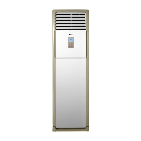
DM16-01.01.25en Floor Standing MFM 7.External view and display 7.1 External view This unit consists of indoor unit and outdoor unit. Note: All the pictures in this manual are for explanation purpose only. They may be slightly different from the air conditioner you purchased (depend on model). The actual shape shall prevail. -
Page 34: Control Panel
Floor Standing MFM DM16-01.01.25en 7.2 Control Panel Control Buttons and Functions Service manual... -
Page 35: Operation Characteristics
DM16-01.01.25en Floor Standing MFM 8.Operation characteristics Mode Drying Cooling operation Heating operation Temperature operation 17℃~32℃ 0℃~30℃ 17℃~32℃ Room temperature Outdoor temperature 18℃~43℃ -7℃~24℃ 18℃~ 43℃ CAUTION: 1. If air conditioner is used outside of the above conditions, certain safety protection features may come into operation and cause the unit to function abnormally. -
Page 36: Electronic Function
Floor Standing MFM DM16-01.01.25en 9.Electronic function 9.1 Main data Introduction Ts : Set temperature, T1 : Room temperature T2: Evaporator pipe temperature T3: Condenser pipe temperature T4: Outdoor ambient temperature T5: Compressor discharge temperature 9.2 Main Protection 9.2.1 Time delay for the compressor start-up At the beginning of energizing or after the stop of the compressor, certain time delay will be needed to start the compressor. - Page 37 DM16-01.01.25en Floor Standing MFM T1-TS 9.3.1.3 Indoor fan running rules: When the compressor is on, the indoor fan can be set to high/low/auto. And the anti-cold wind function has the priority. Auto fan action: T1-Ts High 9.3.1.4 Defrost (only available to heating mode) ---Defrosting Conditions Starting Of Defrosting Condition (meet one of the following is ok): (1)Accumulated time when temperature of outdoor heat exchanger coil T3 is below 3°C reaches to...
- Page 38 Floor Standing MFM DM16-01.01.25en --- Ending Of Defrosting Condition (meet one of the following is ok): (1)Time of defrosting lasts 10 minutes. (2) Temperature of outdoor coil T3 is up to 8°C and continues to 80 seconds. (3) Temperature of outdoor coil T3 is up to 15°C. 9.3.1.5 High evaporator coil temp.T2 protection: 9.3.2 Cooling Mode 9.3.2.1 Four-way valve is closed.
- Page 39 DM16-01.01.25en Floor Standing MFM T1-Ts When compressor is on, outdoor fan will follow the below rules:: For single-fan models: The outdoor fan runs all the time. For double-fan models: Fan(below): When compressor is on, the outdoor fan runs all the time. Fan(above): 9.3.2.3 Indoor fan running rules In cooling mode, indoor fan runs all the time and the speed can be selected as high, low and auto.
- Page 40 Floor Standing MFM DM16-01.01.25en When the evaporator coil temp.T2 keeps lower than TE5 for 30 minutes, the compressor and outdoor fan will shut off. When T2 is higher than TE6, the compressor and outdoor fan will restart Condition 2: TE5-2 When the evaporator coil temp.T2 keeps lower than TE5-2 for 20 minutes, the compressor and outdoor fan will shut off.
-
Page 41: Dehumidifying Mode
DM16-01.01.25en Floor Standing MFM 9.3.2.5 Condenser high temperature T3 protection When high condenser temp. T3 is more than setting value,for setting time the compressor will stop. 9.3.3 Dehumidifying Mode 9.3.3.1 Indoor fan speed is low. 9.3.3.2 Four-way valve is closed, the compressor and outdoor fan will operate the same as in cooling mode. 9.3.4 Auto Mode 9.3.4.1. -
Page 42: Other Functions
Floor Standing MFM DM16-01.01.25en Other Functions 9.4.1 LCD display Mode, Set temp, fan speed, time, timer, protection etc. 9.4.2 Timer function 9.4.2.1 Timing range is 24 hours. 9.4.2.2 Timer on. The machine will turn on automatically when reaching the setting time. 9.4.2.3 Timer off. -
Page 43: Trouble Shooting
DM16-01.01.25en Floor Standing MFM 10.Trouble shooting 10.1 Self-diagnosis 10.1.1 LEDs for the indication of indoor trouble For 24K Codes Contents Temperature protection of indoor evaporator Temperature protection of outdoor condenser Anti-cold air(For heat pump models) Open- or short-circuit of T1 temperature sensor Open- or short-circuit of T2 temperature sensor Open- or short-circuit of T3 temperature sensor Protection of outdoor unit... - Page 44 Floor Standing MFM DM16-01.01.25en 10.1.2 LEDs for the indication of outdoor trouble (only for 48K-50K) Their codes are listed in the following table: LED2(green) LED3(yellow) LED4(red) Contents Standby Flash Lack of phase Flash Phase sequence error Communication malfunction between indoor unit Flash Flash and outdoor unit...
-
Page 45: Troubles And Solutions
DM16-01.01.25en Floor Standing MFM 10.2 Troubles and Solutions Before calling for service, please review the following list of common problems and solutions. Problem Possible Cause Solutions Air conditioner Power failure Wait for power restoring does not The power supply is disconnected. Switch on the main power operate at all switch... - Page 46 Floor Standing MFM DM16-01.01.25en 10.2.1 Open or short circuit of temperature sensor(T1,T2,T3,T4) 10.2.2 Open or short circuit of temperature sensor(T5) Service manual...
- Page 47 DM16-01.01.25en Floor Standing MFM 10.2.3 Default phase of compressor 10.2.4 Phase sequence error Phase sequence error Change the order of the wires to power supply. Switch on the unit again. If the problem cannot be solved, the outdoor PCB is defective Service manual...
- Page 48 Floor Standing MFM DM16-01.01.25en 10.2.5 High temperature protection of condenser High temperature protection of condenser Check the resistance of the temp. sensor according to Appendix 1, is it normal? Possible reason Replace the sensor 1. Air or other gas in the refrigerant. 2.
- Page 49 DM16-01.01.25en Floor Standing MFM 10.2.7 Low temperature protection Low temperature protection Possible reason 1: The outdoor ambient temp. is low. 2: The wires are loose to the temp. sensor. 3: The temp. sensor is defective. 4: The evaporator or the filter is dirty. 5: System has block. ...
- Page 50 Floor Standing MFM DM16-01.01.25en 10.2.9 Overload of current Service manual...
- Page 51 DM16-01.01.25en Floor Standing MFM 10.2.10 Communication malfunction between indoor unit and outdoor unit Service manual...
- Page 52 Floor Standing MFM DM16-01.01.25en 10.2.11 Refrigerant Leakage Detection Service manual...
- Page 53 DM16-01.01.25en Floor Standing MFM 10.2.12 Temperature protection of compressor discharge Service manual...
- Page 54 Floor Standing MFM DM16-01.01.25en Appendix 1 Temperature Sensor Resistance Value Table (℃‐‐K) K Ohm K Ohm K Ohm K Ohm ℃ ℃ ℃ ℃ 115.266 ‐20 20 12.6431 60 2.35774 100 0.62973 ‐19 108.146 21 12.0561 61 2.27249 101 0.61148 ‐18 101.517 22 11.5000 62 2.19073 ...
- Page 55 DM16-01.01.25en Floor Standing MFM Appendix 2 Unit: ℃‐‐‐K Discharge temp. sensor table ‐20 542.7 20 68.66 60 13.59 100 3.702 ‐19 511.9 21 65.62 ...