Table of Contents
Advertisement
Advertisement
Chapters
Table of Contents

Related Manuals for Midea MOBA30U-12HN1-Q


Summary of Contents for Midea MOBA30U-12HN1-Q
- Page 1 50Hz R410A ON/OFF SERIES Service Manual 2017 Contents...
- Page 3 Content Part 1 General Information ..............1 Part 2 Indoor Units .................. 8 Part 3 Outdoor Units ................167 Part 4 Installation ................189 Part 5 Electrical Control System ............231 ※The specifications, designs, and information in this book are subject to change without notice for product improvement.
-
Page 5: Table Of Contents
General Information Part 1 General Information 1. Model Lists ................2 2. External Appearance ............. 5 2.1 Indoor Units ..................... 5 2.2 Outdoor Units ..................6 3. Nomenclature ................. 7 General Information... -
Page 6: Model Lists
● ● Cooling only ● E2 Floor-standing Cooling and heating 1.2 Outdoor Units Universal Outdoor unit Model Compressor type Compressor Brand Matched indoor units Heat Pump MCA3-12HRN1-Q MOBA30U-12HN1-Q ROTARY GMCC MUE-12HRN1-Q MTB-12HWN1-Q MCA3-18HRN1-Q MUE-18HRN1-Q MOBA30U-18HN1-Q ROTARY GMCC MTB-18HWN1-Q MCD-18HRN1-Q MTI-18HWN1-Q... - Page 7 Model Lists MUE-36HRN1-Q MHG-36HWN1-Q MCD-36HRN1-R MUE-36HRN1-R MOD31U-36HN1-R SCROLL EMERSON MHG-36HWN1-R MTI-36HWN1-R MOU-48HN1-R MFJ-48ARN1-R SCROLL Panasonic (22023016000109) MUE-48HRN1-R MFS4-48ARN1-R MOU-48HN1-R MHG-48HWN1-R SCROLL Panasonic (22023016000194) MTB-48HWN1-R MCD-48HRN1-R MFE-60ARN1-R MOE30U-60HN1-R SCROLL Panasonic MTI-60HWN1-R MUE-60HRN1-R MTB-60HWN1-R MOUA-60HN1-R SCROLL Panasonic MCD-60HRN1-R MHG-60HWN1-R Cooling only MOAB30U-09CN1-Q ROTARY GMCC MTB-09CWN1-Q...
- Page 8 Model Lists MUE-60CRN1-R MTB-60CWN1-R MTI-60CWN1-R General Information...
-
Page 9: External Appearance
External Appearance External Appearance External Appearance 2. External Appearance External Appearance External Appearance 2.1 Indoor Units 2.1 Indoor Units 2.1 Indoor Units Compact Four Compact Four Compact Four-way cassette way cassette Super Super-slim 4-way Cassette way Cassette A5 Middle static pressure duct A5 Middle static pressure duct A5 Middle static pressure duct A5 Middle static pressure duct... -
Page 10: Outdoor Units
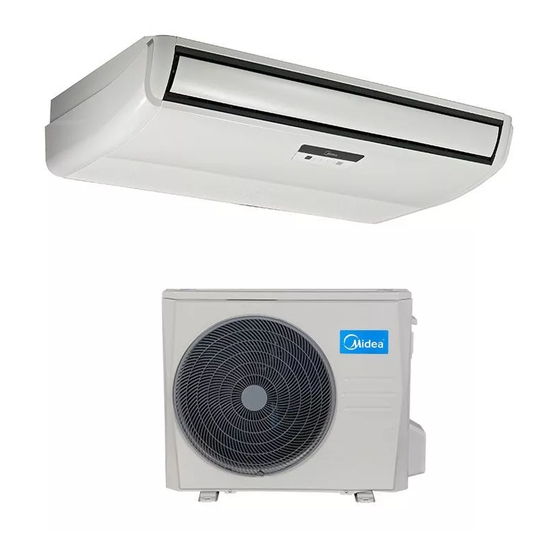
External Appearance External Appearance External Appearance S2 Floor S2 Floor-standing standing S4 Floor S4 Floor-standing standing 2.2 Outdoor Units 2.2 Outdoor Units 2.2 Outdoor Units Single fan outdoor unit Single fan outdoor unit Single fan outdoor unit Double fan outdoor unit Double fan outdoor unit Double fan outdoor unit General Information... -
Page 11: Nomenclature
V AHU Type T Duct Type F Console Type U Ceiling & Floor Type H High Static Pressure Duct Type Midea 3.2 Outdoor Unit M O T4 D30 U- 36 H D N1- R RC4 Energy Efficiency Code Power Supply... - Page 12 Indoor Units Part 2 Indoor Units Four-way Cassette Type (Compact) ........9 Super-slim Cassette Type ..........19 A5 Duct Type ............... 37 A6 Duct Type ............... 57 High Static Pressure Duct Type ........77 Ceiling & Floor Type ............94 GA Floor-standing Type ...........
- Page 13 MLCAC-UTSM TSM-2010-10 New Four-way Cassette Type way Cassette Type way Cassette Type Four-way Cassette way Cassette way Cassette Type (Compact) Type (Compact) Type (Compact) Type (Compact) Features Features ................................................................10 Dimensions Dimensions ..............
- Page 14 Features Features Features Features 1.1 New 1.1 New panel panel 360°surrounding air outlet design, affords comfortable feeling 360°surrounding air outlet design, affords comfortable feeling 360°surrounding air outlet design, affords comfortable feeling 360°surrounding air outlet design, affords comfortable feeling 360°surrounding air outlet design, affords comfortable feeling 360°surrounding air outlet design, affords comfortable feeling 1.2 Compact design...
- Page 15 Dimensions Dimensions Dimensions Dimensions Four Four-way Cassette Type(Compact) way Cassette Type(Compact) way Cassette Type(Compact)
- Page 16 Service Space Service Space Service Space Service Space Service Space Four-way Cassette Type( way Cassette Type( way Cassette Type(Compact) Compact)
- Page 17 Air Velocity and T Air Velocity and T Air Velocity and Temperature Distributions(Reference Data) emperature Distributions(Reference Data) emperature Distributions(Reference Data) emperature Distributions(Reference Data) Air Velocity and Temperature Distributions(Reference Data) Air Velocity and Temperature Distributions(Reference Data) Air Velocity and Temperature Distributions(Reference Data) Air Velocity and Temperature Distributions(Reference Data) Air Velocity and Temperature Distributions(Reference Data) Air Velocity and Temperature Distributions(Reference Data)
- Page 18 Wiring Diagrams Wiring Diagrams Wiring Diagrams Wiring Diagrams Wiring Diagrams Wiring Diagrams MCA3 MCA3-12HRN1 12HRN1-Q, MCA3 Q, MCA3-18HRN1-Q MCA3 MCA3-12CRN1 12CRN1-QB6, MCA3 MCA3-18CRN1 18CRN1-QB5 Four-way Cassette Type( way Cassette Type( way Cassette Type(Compact) Compact)
- Page 19 Electric Characteristics Electric Characteristics Electric Characteristics Electric Characteristics Electric Characteristics Electric Characteristics Electric Characteristics Power Power Indoor Units Indoor Units Supply Supply Model Voltage Min. Max. MCA3 MCA3-12CRN1 12CRN1-QB6 220-240V 198V 254V MCA3 MCA3-12HRN1 12HRN1-Q 220-240V 198V 254V MCA3 MCA3-18CRN1 18CRN1-QB5 220-240V 198V...
- Page 20 Indoor Units Indoor Units Accessories Accessories Name Shape Quantity 1. Expansible hook 1. Expansible hook Installation fittings Installation fittings Installation fittings 2. Installation hook 2. Installation hook 3. Installation paper board Installation paper board Installation paper board 4. Out-let pipe sheath let pipe sheath 5.
- Page 21 The Specification of Power The Specification of Power The Specification of Power The Specification of Power The Specification of Power The Specification of Power The Specification of Power MCA3-12CRN1 12CRN1-QB6 MCA3 MCA3-12HRN1-Q Type MCA3-18CRN1 18CRN1-QB5 MCA3 MCA3-18HRN1-Q Phase Phase 1-phase phase 1-phase Power...
- Page 22 Indoor Units Indoor Units 10. Field Wiring Field Wiring Field Wiring Four-way Cassette Type( way Cassette Type( way Cassette Type(Compact) Compact)
- Page 23 Super-slim Cassette Type Super-slim Cassette Type 1. Features ................20 2. Dimensions ..............23 3. Service Space ..............24 4. Wiring Diagrams ............. 25 5. Electric Characteristics ..........30 6. Sound Levels ..............31 7. Accessories ..............32 8. The Specification of Power ..........33 9.
-
Page 24: Features
Features 1. Features 1.1 Overview Compact design, super slim body size, less space requiring in installation Each louver can be separately controlled, more comfort air blowing is possible. Auto-lifting panel design, more convenient to clean and maintain the filter. (optional) Fresh air intake function ... - Page 25 Features Features Ionizer generator Ionizer generator Ventilation motor Ventilation motor connector connector connector connector Ionizer can be switched on or off by remote controller. Ionizer can be switched on or off by remote controller. Ionizer can be switched on or off by remote controller. Ionizer can be switched on or off by remote controller.
- Page 26 Features Features Draining Pump Draining Pump Built-in draining pump to make sure condensed water drain out reliably. in draining pump to make sure condensed water drain out reliably. in draining pump to make sure condensed water drain out reliably. in draining pump to make sure condensed water drain out reliably.
-
Page 27: Dimensions
Dimensions 2. Dimensions 92 92 Fresh air intake 4-install hanger Body Gas side Liquid side Wiring connection port E-parts box Service hole for Test mouth & Test cover draining pump Drain hole 92 92 92 92 Panel Unit: mm Model 18/24 30~48 Super-slim Cassette Type... -
Page 28: Service Space
Service Space 3. Service Space >1000m m >1000mm Super-slim Cassette Type... -
Page 29: Wiring Diagrams
Wiring Diagrams 4. Wiring Diagrams MCD-18HRN1-Q MCD-24HRN1-Q, MCD-36HRN1-Q Super-slim Cassette Type... - Page 30 Indoor Units MCD-36HRN1-R Super-slim Cassette Type...
- Page 31 Wiring Diagrams MCD-48HRN1-R, MCD-60HRN1-R Super-slim Cassette Type...
- Page 32 Indoor Units MCD-18CRN1-Q, MCD-18CRN1-QC0 MCD-24CRN1-Q, MCD-24CRN1-QB9, MCD-30CRN1-QB4, MCD-36CRN1-QB4, MCD-36CRN1-QB6 Super-slim Cassette Type...
- Page 33 Wiring Diagrams MCD-36CRN1-RB4, MCD-48CRN1-RB4, MCD-60CRN1-R MCD-48CRN1-RB4 Super-slim Cassette Type...
-
Page 34: Electric Characteristics
Indoor Units 5. Electric Characteristics Indoor Unit Power Supply Model Voltage MCD-18HRN1-Q 220-240V 198V 254V MCD-24HRN1-Q 220-240V 198V 254V MCD-36HRN1-Q 220-240V 198V 254V MCD-36HRN1-R 220-240V 198V 254V MCD-48HRN1-R 380-415V 342V 436V MCD-60HRN1-R 380-415V 342V 436V MCD-18CRN1-Q 220-240V 198V 254V MCD-18CRN1-QC0 220-240V 198V 254V... -
Page 35: Sound Levels
Sound Levels 6. Sound Levels 1.4m Microphone Noise level dB(A) Model MCD-18HRN1-Q MCD-24HRN1-Q MCD-36HRN1-Q MCD-36HRN1-R MCD-48HRN1-R MCD-60HRN1-R MCD-24CRN1-QB9 MCD-18CRN1-Q MCD-18CRN1-QC0 MCD-24CRN1-Q MCD-30CRN1-QB4 MCD-36CRN1-QB4 MCD-36CRN1-RB4 MCD-36CRN1-QB6 MCD-48CRN1-RB4(22022511000996) MCD-48CRN1-RB4(22022511001076) MCD-60CRN1-R Super-slim Cassette Type... -
Page 36: Accessories
Indoor Units 7. Accessories Name Shape Quantity Installation paper board INSTALLATION FITTINGS Bolt M5 Tubing & Fittings Soundproof / insulation sheath Out-let pipe Out-let pipe sheath Drainpipe Fittings Out-let pipe clasp Remote controller & Its Frame Remote controller holder Remote controller & Its Frame Mounting screw(ST2.9×10-C-H) Remote controller manual... -
Page 37: The Specification Of Power
The Specification of Power The Specification of Power The Specification of Power 8. The Specification of Power The Specification of Power The Specification of Power The Specification of Power Cooling only: Cooling only: Cooling only: Model (KBtu/h) Model (KBtu/h) Model (KBtu/h) 30-36 48~60 48~60... -
Page 38: Field Wiring
Indoor Units 9. Field Wiring MCD-18HRN1-Q, MCD-18CRN1-Q, MCD-18CRN1-QC0 MCD-24CRN1-QB9, MCD-36CRN1-QB4 Super-slim Cassette Type... - Page 39 Field Wiring MCD-24HRN1-Q, MCD-24CRN1-Q, MCD-30CRN1-QB4 MCD-36HRN1-Q, MCD-36CRN1-QB6 Super-slim Cassette Type...
- Page 40 Indoor Units MCD-36HRN1-R MCD-36CRN1-RB4, MCD-48CRN1-RB4, MCD-60CRN1-R, MCD-48HRN1-R, MCD-60HRN1-R Super-slim Cassette Type...
- Page 41 A5 Duct Type A5 Duct Type 1. Features ................38 2. Dimensions ..............41 3. Service Space ..............42 4. Wiring Diagrams ............. 43 5. Static Pressure ..............47 6. Electric Characteristics ..........50 7. Sound Levels ..............51 8. Accessories ..............52 9.
-
Page 42: Features
Features Features 1. Features Features 1.1 Installation accessories: (Optional) 1.1 Installation accessories: (Optional) 1.1 Installation accessories: (Optional) 1.1 Installation accessories: (Optional) 1.1 Installation accessories: (Optional) Front Board, Canvas Air Passage, Filter, Panel, for easy installation Front Board, Canvas Air Passage, Filter, Panel, for easy installation Front Board, Canvas Air Passage, Filter, Panel, for easy installation Front Board, Canvas Air Passage, Filter, Panel, for easy installation Front Board, Canvas Air Passage, Filter, Panel, for easy installation... - Page 43 Features Features Motor Blower Housing Blower Housing Ventilated Panel Ventilated Panel 1.4 Reserved remote on Reserved remote on Reserved remote on-off and central control ports off and central control ports off and central control ports off and central control ports ...
- Page 44 Features Features 1.6 Built-in display board in display board in display board The standard indoor unit can be controlled by wired controller. The standard indoor unit can be controlled by wired controller. The standard indoor unit can be controlled by wired controller. The standard indoor unit can be controlled by wired controller.
-
Page 45: Dimensions
Dimensions 2. Dimensions air inlet from rear side Air filter ( optional ) 4-install hanger Liquid side 25 Drain pipe Gas side 25 Drain pipe Test mouth & Test cover 25 Drain connecting pipe ( for pump ) Fresh air intake Electric control box Air filter ( optional ) air inlet from bottom side... -
Page 46: Service Space
Service Space 3. Service Space Ensure enough space required for installation and maintenance. Duct Type... -
Page 47: Wiring Diagrams
Wiring Diagrams 4. Wiring Diagrams MTB-12HWN1-Q, MTB-18HWN1-Q MTB-24HWN1-Q A5 Duct Type... - Page 48 Wiring Diagrams MTB-09CWN1-Q, MTB-12CWN1-QB6, MTB-18CWN1-QB5 MTB-24CWN1-Q, MTB-30CWN1-QB4, MTB-36CWN1-QB4 Duct Type...
- Page 49 Wiring Diagrams MTB-36CWN1-QB6 MTB-36CWN1-RB4, MTB-48CWN1-R, MTB-60CWN1-R A5 Duct Type...
- Page 50 Wiring Diagrams MTB-48HWN1-R, MTB-60HWN1-R Duct Type...
-
Page 51: Static Pressure
Static Pressure 5. Static Pressure 9K/12K External static pressure (Pa) 1200 1000 External static pressure (Pa) 1600 1400 1200 1000 External static pressure (Pa) A5 Duct Type... - Page 52 Static Pressure 2000 1800 1600 1400 1200 1000 External static pressure (Pa) 2500 2000 1500 1000 External static pressure (Pa) 3000 2500 2000 1500 1000 External static pressure (Pa) Duct Type...
- Page 53 Static Pressure 3000 2500 2000 1500 1000 External static pressure (Pa) A5 Duct Type...
-
Page 54: Electric Characteristics
Electric Characteristics lectric Characteristics Indoor Units Power Supply Model Voltage Min. Max. MTB-12HWN1-Q 220-240V 198V 254V MTB-18HWN1-Q 220-240V 198V 254V MTB-24HWN1-Q 220-240V 198V 254V MTB-48HWN1-R 380-415V 342V 436V MTB-60HWN1-R 380-415V 342V 436V MTB-09CWN1-Q 220-240V 198V 254V MTB-12CWN1-QB6 220-240V 198V 254V MTB-18CWN1-QB5 220-240V 198V... -
Page 55: Sound Levels
Sound Levels 7. Sound Levels Concealed Duct Type Discharge Suction Duct Duct 1.4m Microphone Noise level dB(A) Model MTB-12HWN1-Q MTB-18HWN1-Q MTB-24HWN1-Q MTB-48HWN1-R MTB-60HWN1-R MTB-09CWN1-Q MTB-12CWN1-QB6 MTB-18CWN1-QB5 MTB-24CWN1-Q MTB-30CWN1-QB4 MTB-36CWN1-QB4 MTB-36CWN1-QB6 MTB-36CWN1-RB4 MTB-48CWN1-R MTB-60CWN1-R A5 Duct Type... -
Page 56: Accessories
Accessories 8. Accessories Name Shape Quantity Soundproof/insulation sheath Tubing & Fittings Binding tape Seal sponge Drain joint Drainpipe Fittings Seal ring Wire controller Wire controller Owner's manual others Installation manual Duct Type... -
Page 57: The Specification Of Power
The Specification of Power The Specification of Power The Specification of Power 9. The Specification of Power The Specification of Power The Specification of Power The Specification of Power Cooling only: Cooling only: Cooling only: Model (KBtu/h) Model (KBtu/h) Model (KBtu/h) 12-18 30-36 48~60... -
Page 58: Field Wiring
Field Wiring 10. Field Wiring MTB-09CWN1-Q MTB-12CWN1-QB6, MTB-18CWN1-QB5 Duct Type... - Page 59 Field Wiring MTB-12HWN1-Q, MTB-18HWN1-Q MTB-24HWN1-Q, MTB-24CWN1-Q, MTB-30CWN1-QB4, MTB-36CWN1-QB4 A5 Duct Type...
- Page 60 Field Wiring MTB-36CWN1-QB6 MTB-36CWN1-RB4, MTB-48CWN1-R, MTB-60CWN1-R, MTB-48HWN1-R, MTB-60HWN1-R Duct Type...
- Page 61 A6 Duct Type A6 Duct Type 1. Features ................58 2. Dimensions ..............61 3. Service Space ..............62 4. Wiring Diagrams ............. 63 5. Static Pressure ..............68 6. Electric Characteristics ..........70 7. Sound Levels ..............71 8. Accessories ..............72 9.
-
Page 62: Features
Features Features 1. Features Features 1.1 Slim Design Design The industry Lowest height is designed to be fitted into tight roof spaces. The industry Lowest height is designed to be fitted into tight roof spaces. The industry Lowest height is designed to be fitted into tight roof spaces. The industry Lowest height is designed to be fitted into tight roof spaces. - Page 63 Features 1.4 Easy Clean Clean the filter (Optional, standard product without filter) It is easy to draw out the filter from the indoor unit for cleaning, even the filter is installed in rear side or bottom side. With a larger window design, once the motor and the blower wheels have been detached, heat exchanger and water receiver tray in behind can be seen very clearly.
- Page 64 Features Features 1.6 Built 1.6 Built-in drain pump (Optional) in drain pump (Optional) in drain pump (Optional) Built-in drain pump can lift the water to 750mm upmost, in drain pump can lift the water to 750mm upmost, in drain pump can lift the water to 750mm upmost, in drain pump can lift the water to 750mm upmost, in drain pump can lift the water to 750mm upmost, in drain pump can lift the water to 750mm upmost, which widens the drainage piping range.
-
Page 65: Dimensions
Dimensions 2. Dimensions Note: standard product without filter Unit: mm Size of install Outline dimension(mm) Air outlet opening size Air return opening size Size of refrigerant pipe hanger Model 24K~36K 1100 1001 1140 48K~60K 1200 1044 1101 1240 A6 Duct Type... -
Page 66: Service Space
Service Space 3. Service Space Ensure enough space required for installation and maintenance. There is enough space for installation and maintenance. The ceiling is horizontal, and its structure can endure the weight of the indoor unit. The outlet and the inlet are not impeded, and the influence of external air is the least. -
Page 67: Wiring Diagrams
Wiring Diagrams 4. Wiring Diagrams MTI-18HWN1-Q MTI-24HWN1-Q A6 Duct Type... - Page 68 Wiring Diagrams MTI-30HWN1-Q, MTI-36HWN1-Q MTI-36HWN1-R Duct Type...
- Page 69 Wiring Diagrams MTI-60HWN1-R MTI-18CWN1-Q A6 Duct Type...
- Page 70 Wiring Diagrams MTI-24CWN1-Q MTI-30CWN1-Q Duct Type...
- Page 71 Wiring Diagrams MTI-36CWN1-R, MTI-60CWN1-R MTI-48CWN1-R A6 Duct Type...
-
Page 72: Static Pressure
Static Pressure Static Pressure 1200 1000 External Static Pressure (Pa) 24K, MTI-30CWN1-Q 2000 1800 1600 1400 1200 1000 External Static Pressure (Pa) Duct Type... - Page 73 Static Pressure MOD30U-30HN1-Q,36K 2000 1800 1600 1400 1200 1000 External Static Pressure (Pa) 48K, 60K 3500 3000 2500 2000 1500 1000 External Static Pressure (Pa) A6 Duct Type...
-
Page 74: Electric Characteristics
Electric Characteristics lectric Characteristics Power Supply Indoor Units Model Voltage Min. Max. MTI-18HWN1-Q 220-240V 198V 254V MTI-24HWN1-Q 220-240V 198V 254V MTI-30HWN1-Q 220-240V 198V 254V MTI-36HWN1-Q 220-240V 198V 254V MTI-36HWN1-R 220-240V 198V 254V MTI-60HWN1-R 220-240V 198V 254V MTI-18CWN1-Q 220-240V 198V 254V MTI-24CWN1-Q 220-240V 198V... -
Page 75: Sound Levels
Sound Levels 7. Sound Levels Concealed Duct Type Discharge Suction Duct Duct 1.4m Microphone Noise level dB(A) Model MTI-18HWN1-Q MTI-24HWN1-Q MTI-30HWN1-Q MTI-36HWN1-Q MTI-36HWN1-R MTI-60HWN1-R MTI-18CWN1-Q MTI-24CWN1-Q MTI-30CWN1-Q MTI-36CWN1-R MTI-48CWN1-R MTI-60CWN1-R A6 Duct Type... -
Page 76: Accessories
Accessories 8. Accessories Name Shape Quantity Soundproof/insulation sheath Tubing & Fittings Binding tape Seal sponge Drain joint Drainpipe Fittings (for cooling &heating units) Seal ring Wire controller Wire controller Owner's manual others Installation manual Duct Type... -
Page 77: The Specification Of Power
The Specification of Power The Specification of Power The Specification of Power 9. The Specification of Power The Specification of Power The Specification of Power The Specification of Power Cooling only: Cooling only: Cooling only: Model (KBtu/h) Model (KBtu/h) Model (KBtu/h) Phase Phase 1-phase... -
Page 78: Field Wiring
Field Wiring 10. Field Wiring MTI-18HWN1-Q MTI-24HWN1-Q Duct Type... - Page 79 Field Wiring MTI-30HWN1-Q, MTI-36HWN1-Q, MTI-24CWN1-Q, MTI-30CWN1-Q MTI-36HWN1-R, MTI-36CWN1-R, MTI-48CWN1-R, MTI-60HWN1-R A6 Duct Type...
- Page 80 Field Wiring MTI-18CWN1-Q MTI-48HWN1-R, MTI-60CWN1-R Duct Type...
- Page 81 Field Wiring High Static Pressure Duct Type 1. Features ................78 2. Dimensions ..............80 3. Service Space ..............81 4. Wiring Diagrams ............. 82 5. Static Pressure ..............87 6. Electric Characteristics ..........88 7. Sound Levels ..............89 8.
-
Page 82: Features
Features Features Features Features 1.1 High static pressure design 1.1 High static pressure design 1.1 High static pressure design 1.1 High static pressure design 1.1 High static pressure design Max static pressure of indoor unit is 160Pa. Max static pressure of indoor unit is 160Pa. Max static pressure of indoor unit is 160Pa. - Page 83 Features High Static Pressure Duct Type...
-
Page 84: Dimensions
Dimensions 2. Dimensions Unit: mm Capacity Size of Outline dimension Air outlet opening size Air inlet opening size (KBtu) mounted lug 1110 1146 1054 1061 48/60 1200 1236 1000 1145 High Static Pressure Duct Type... -
Page 85: Service Space
Service Space 3. Service Space Ensure enough space required for installation and maintenance. 500mm or more 600mm or more Indoor unit Maintenance and repair space 600mmx600mm High Static Pressure Duct Type... -
Page 86: Wiring Diagrams
Wiring Diagrams Wiring Diagrams MHG-24HWN1-Q High Static Pressure Duct Type... - Page 87 Wiring Diagrams MHG-36HWN1-R MHG-36HWN1-Q High Static Pressure Duct Type...
- Page 88 Wiring Diagrams High Static Pressure Duct Type...
- Page 89 Wiring Diagrams MHG-48HWN1-R High Static Pressure Duct Type...
- Page 90 Wiring Diagrams MHG-60HWN1-R High Static Pressure Duct Type...
-
Page 91: Static Pressure
Static Pressure 5. Static Pressure 1800 1600 1400 1200 1000 External static pressure (Pa) 2500 2000 1500 1000 100 110 120 130 140 150 External static pressure (Pa) 48/60K 4000 3500 3000 2500 2000 1500 1000 0 10 20 30 40 50 60 70 80 90 100 110 120 130 140 150 160 170 180 190 200 External static pressure (Pa) High Static Pressure Duct Type... -
Page 92: Electric Characteristics
Electric Characteristics 6. Electric Characteristics Indoor Unit Power Supply Model Voltage Min. Max. MHG-24HWN1-Q 220-240V 198V 254V MHG-36HWN1-R 220-240V 198V 254V MHG-36HWN1-Q 220-240V 198V 254V MHG-48HWN1-R 380-415V 342V 436V MHG-60HWN1-R 380-415V 342V 436V Notes: MFA: Max. Fuse Amps. (A) High Static Pressure Duct Type... -
Page 93: Sound Levels
Sound Levels 7. Sound Levels Concealed Duct Type Discharge Suction Duct Duct 1.5m Microphone Noise level dB(A) Model MHG-24HWN1-Q MHG-36HWN1-R MHG-36HWN1-Q MHG-48HWN1-R MHG-60HWN1-R High Static Pressure Duct Type... -
Page 94: Accessories
Accessories Accessories Accessories Accessories Name Shape Shape Quantity Quantity Tubing & Fittings Tubing & Fittings Tubing & Fittings Soundproof / insulation sheath Soundproof / insulation sheath Soundproof / insulation sheath Soundproof / insulation sheath Drain joint Drain joint Drainpipe Fittings Drainpipe Fittings Drainpipe Fittings (for cooling &... -
Page 95: The Specification Of Power
The Specification of Power The Specification of Power The Specification of Power 9. The Specification of Power The Specification of Power The Specification of Power The Specification of Power Model (KBtu/h) Model (KBtu/h) Model (KBtu/h) 48~60 Phase 1-phase 1-phase phase 3-phase phase 3-phase... -
Page 96: Field Wiring
Field Wiring 10. Field Wiring MHG-24HWN1-Q MHG-36HWN1-R High Static Pressure Duct Type... - Page 97 Field Wiring MHG-36HWN1-Q MHG-48HWN1-R, MHG-60HWN1-R High Static Pressure Duct Type...
- Page 98 Ceiling & Floor Type Ceiling & Floor Type 1. Features ................95 2. Dimensions ..............96 3. Service Space ..............97 4. Wiring Diagram ............... 98 5. Electric Characteristics ..........103 6. Sound Levels ..............104 7. Accessories ..............105 8. The Specification of Power ..........106 9.
-
Page 99: Features
Features Features 1.1. New design, more modern and elegant appearance. 1.2. Convenient installation --The ceiling type can be easily installed into a corner of the ceiling even if the ceiling is very narrow --It is especially useful when installation of an air conditioner in the center of the ceiling is impossible due to a structure such as one lighting. -
Page 100: Dimensions
Dimensions Dimensions Wiring connection port Drain discharge port Fresh air intake Refrigerant pipe hole Hanging arm Capacity (Btu/h) 12~24K 1068 30~36K 1285 1200 48~60K 1650 1565 Ceiling & Floor Type... -
Page 101: Service Space
Service Space Service Space Ceiling & Floor Type... -
Page 102: Wiring Diagram
Wiring Diagram Wiring Diagram MUE-12HRN1-Q,MUE-18HRN1-Q MUE-24HRN1-Q, MUE-30HRN1-Q Ceiling & Floor Type... - Page 103 Wiring Diagram MUE-36HRN1-R MUE-36HRN1-Q Ceiling & Floor Type...
- Page 104 Wiring Diagram MUE-48HRN1-R, MUE-60HRN1-R MUE-18CRN1-QB5 Ceiling & Floor Type...
- Page 105 Wiring Diagram MUE-24CRN1-Q, MUE-30CRN1-QB4, MUE-36CRN1-QB4 MUE-36CRN1-QB6 Ceiling & Floor Type...
- Page 106 Wiring Diagram MUE-36CRN1-RB4, MUE-48CRN1-RB4, MUE-60CRN1-R Ceiling & Floor Type...
-
Page 107: Electric Characteristics
Electric Characteristics Electric Characteristics Indoor Units Power Supply Model Voltage Min. Max. MUE-12HRN1-Q 220-240V 198V 242V MUE-18HRN1-Q 220-240V 198V 242V MUE-24HRN1-Q 220-240V 198V 242V MUE-30HRN1-Q 220-240V 198V 242V MUE-36HRN1-Q 220-240V 198V 242V MUE-36HRN1-R 220-240V 198V 242V MUE-48HRN1-R 380-415V 342V 436V MUE-60HRN1-R 380-415V 342V... -
Page 108: Sound Levels
Sound Levels Sound Levels Microphone 1.5m Air outlet side Microphone Ceiling Floor Noise level dB(A) Model MUE-12HRN1-Q MUE-18HRN1-Q MUE-24HRN1-Q MUE-30HRN1-Q MUE-36HRN1-Q MUE-36HRN1-R MUE-48HRN1-R MUE-60HRN1-R MUE-18CRN1-QB5 MUE-24CRN1-Q MUE-30CRN1-QB4 MUE-36CRN1-QB4 MUE-36CRN1-QB6 MUE-36CRN1-RB4 MUE-48CRN1-RB4 MUE-60CRN1-R Ceiling & Floor Type... -
Page 109: Accessories
Accessories Accessories Accessories Accessories Accessories 1. Remote controller Remote controller Remote controller & Its Remote controller & Its Remote controller & Its 2. Remote controller holder 2. Remote controller holder 2. Remote controller holder holder holder 3. Mounting screw (ST2.9×10 3. -
Page 110: The Specification Of Power
The Specification of Power The Specification of Power The Specification of Power The Specification of Power The Specification of Power The Specification of Power The Specification of Power Cooling only: Cooling only: Cooling only: Model (KBtu/h) Model (KBtu/h) Model (KBtu/h) 30-36 48~60 Phase... -
Page 111: Field Wiring
Field Wiring Field Wiring MUE-18CRN1-QB5 MUE-12HRN1-Q, MUE-18HRN1-Q Ceiling & Floor Type... - Page 112 Field Wiring MUE-24HRN1-Q, MUE-24CRN1-Q, MUE-30CRN1-QB4, MUE-36CRN1-QB4 MUE-36HRN1-R Ceiling & Floor Type...
- Page 113 Field Wiring MUE-30HRN1-Q, MUE-36HRN1-Q, MUE-36CRN1-QB6 MUE-36CRN1-RB4, MUE-48CRN1-RB4, MUE-60CRN1-R. MUE-48HRN1-R,MUE-60HRN1-R Ceiling & Floor Type...
- Page 114 GA Floor GA Floor-standing Type standing Type Floor Floor-standing Type standing Type standing Type standing Type Features Features Features ................................................. 111 Dimensions Dimensions Dimensions ..............................................112 Service Space Service Space Service Space ........
- Page 115 Features Features Features Features 1.1. 1.1.Simple and bright panel Simple and bright panel Simple and bright panel Adopts simple and bright style panel, GA series are suitable for most different space, and show in good Adopts simple and bright style panel, GA series are suitable for most different space, and show in good Adopts simple and bright style panel, GA series are suitable for most different space, and show in good Adopts simple and bright style panel, GA series are suitable for most different space, and show in good Adopts simple and bright style panel, GA series are suitable for most different space, and show in good...
- Page 116 Dimensions Dimensions Dimensions Dimensions Dimension Dimension Dimension W(mm) W(mm) D(mm) H(mm) Model Model 18~24 1695 1800 1925 GA Floor GA Floor-standing type standing type...
- Page 117 Service Space Service Space Service Space Service Space Service Space GA Floor GA Floor-standing type standing type...
- Page 118 Wiring Diagrams Wiring Diagrams Wiring Diagrams Wiring Diagrams Wiring Diagrams Wiring Diagrams MFGA MFGA-24ARN1 24ARN1-Q MFGA MFGA-18CRN1 18CRN1-QB6 GA Floor GA Floor-standing type standing type...
- Page 119 MFGA-24CRN1-Q MFGA-48CRN1-RB4, MFGA-60CRN1-R GA Floor-standing type...
- Page 120 Electric Characteristics Electric Characteristics Electric Characteristics Electric Characteristics Electric Characteristics Electric Characteristics Electric Characteristics Indoor Units Indoor Units Power Supply Power Supply Model Voltage Min. Max. MFGA MFGA-18CRN1-QB6 220-240V 240V 198V 254V MFGA MFGA-24ARN1-Q 220-240V 240V 198V 254V MFGA MFGA-24CRN1- 380-415V 415V 342V...
- Page 121 Accessories Accessories Accessories Accessories Part Name Part Name Shape Quantity Safety Lock Safety Lock Self- -tapping Screw 3.9×25 tapping Screw 3.9×25 Flat Washers Flat Washers Bushing Bushing-Sleeve Cover Sleeve Cover Sound/Heat Insulation Sleeves Sound/Heat Insulation Sleeves Sound/Heat Insulation Sleeves Seal Seal Drain joint Drain joint...
- Page 122 The Specification of Power The Specification of Power The Specification of Power The Specification of Power The Specification of Power The Specification of Power The Specification of Power Input Rated Amp Input Rated Amp Input Rated Amp Model Model Power supply Power supply Power Cord Size Power Cord Size...
- Page 123 M Floor-standing Type M Floor-standing Type 1. Features .................120 2. Dimensions ..............121 3. Service Space ..............122 4. Wiring Diagrams ............123 5. Electric Characteristics ..........125 6. Sound Levels ..............126 7. Accessories ..............127 8. The Specification of Power ..........128 M Floor-standing Type...
-
Page 124: Features
Features 10. Features 10.1 Fashionable design, concise and easy design better suits decoration style. 1.2. Dustproof Air Outlet When press OFF to turn off the unit, the air outlet louver can be closed automatically to prevent the dust falling in. 1.3. -
Page 125: Dimensions
Dimensions 11. Dimensions Dimension W(mm) D(mm) H(mm) Model 1700 1824 1934 M Floor-standing Type... -
Page 126: Service Space
Service Space 12. Service Space M Floor-standing Type... -
Page 127: Wiring Diagrams
Wiring Diagrams 13. Wiring Diagrams MFM-24ARN1-Q MFM-24CRN1-Q M Floor-standing Type... - Page 128 Wiring Diagrams MFM-48CRN1-RB4, MFM-60CRN1-R M Floor-standing Type...
-
Page 129: Electric Characteristics
Electric Characteristics 14. Electric Characteristics Indoor Units Power Supply Model Voltage Min. Max. MFM-24ARN1-Q 220-240V 198V 254V MFM-24CRN1-Q 220-240V 198V 254V MFM-48CRN1-RB4 380-415V 342V 436V MFM-60CRN1-R 380-415V 342V 436V Notes: MFA: Max. Fuse Amps. (A) M Floor-standing Type... -
Page 130: Sound Levels
Sound Levels 15. Sound Levels Microphone Noise level dB(A) Model MFM-24ARN1-Q MFM-24CRN1-Q MFM-48CRN1-RB4 MFM-60CRN1-R M Floor-standing Type... -
Page 131: Accessories
Accessories Accessories 16. Accessories Accessories Part Name Part Name Shape Quantity Safety Lock Safety Lock Self- -tapping Screw 3.9×25 tapping Screw 3.9×25 Flat Washers Flat Washers Bushing Bushing-Sleeve Cover Sleeve Cover Sound/Heat Insulation Sleeves Sound/Heat Insulation Sleeves Sound/Heat Insulation Sleeves Seal Seal Drain joint... -
Page 132: The Specification Of Power
The Specification of Power 17. The Specification of Power Input Rated Amp Model Power supply Power Cord Size (Switch/Fuse)(A) ≥2.5 mm² 24000Btu/h 220-240V 50Hz 32/25 (≥3.3 mm² for with PTC) 48000~60000Btu/h 380-415V 50Hz 32/25 ≥2.5 mm² NOTE: The cable size and the current of the fuse or switch are determined by the maximum current indicated on the nameplate which located on the side panel of the unit. - Page 133 J2 Floor-standing Type J2 Floor-standing Type 1. Features .................130 2. Dimensions ..............131 3. Service Space ..............132 4. Wiring Diagrams ............133 5. Electric Characteristics ..........134 6. Sound Levels ..............135 7. Accessories ..............136 8. The Specification of Power ..........137 J2 Floor-standing Type...
-
Page 134: Features
Features 1. Features 1.1. Classic Design Concise and easy design, with big LED display, dust-proof air outlet and high-polished plastic panel. 36/48K 1.2. Dustproof Air Outlet When press OFF to turn off the unit, the air outlet louver can be closed automatically to prevent the dust falling in. -
Page 135: Dimensions
Dimensions 2. Dimensions Dimension W(mm) D(mm) H(mm) Mode 1700 1825 J2 Floor-standing Type... -
Page 136: Service Space
Service Space 3. Service Space J2 Floor-standing Type... -
Page 137: Wiring Diagrams
The Specification of Power 4. Wiring Diagrams MFJ-24ARN1-Q MFJ-48ARN1-R J2 Floor-standing Type... -
Page 138: Electric Characteristics
Electric Characteristics 5. Electric Characteristics Indoor Units Power Supply Model Voltage Min. Max. MFJ-24ARN1-Q 220-240V 198V 242V MFJ-48ARN1-R 380-415V 342V 436V Notes: MFA: Max. Fuse Amps. (A) J2 Floor-standing Type... -
Page 139: Sound Levels
The Specification of Power 6. Sound Levels Microphone Noise level dB(A) Model MFJ-24ARN1-Q MFJ-48ARN1-R J2 Floor-standing Type... -
Page 140: Accessories
Accessories Accessories 7. Accessories Accessories Part Name Part Name Shape Quantity Safety Lock Safety Lock Self- -tapping Screw 3.9×25 tapping Screw 3.9×25 Flat Washers Flat Washers Bushing Bushing-Sleeve Cover Sleeve Cover Sound/Heat Insulation Sleeves Sound/Heat Insulation Sleeves Sound/Heat Insulation Sleeves Seal Seal Drain joint... -
Page 141: The Specification Of Power
The Specification of Power 8. The Specification of Power Input Rated Amp Model Power supply Power Cord Size (Switch/Fuse)(A) ≥2.5 mm² 24000Btu/h 220-240V 50Hz 32/25 (≥3.3 mm² for with PTC) ≥2.5 mm² 48000~60000Btu/h 380-415V 50Hz 32/25 (≥4.0 mm² for with PTC) NOTE: The cable size and the current of the fuse or switch are determined by the maximum current indicated on the nameplate which located on the side panel of the unit. - Page 142 S2 Floor-standing Type S2 Floor-standing Type 1. Features .................139 2. Dimensions ..............140 3. Service Space ..............141 4. Wiring Diagrams ............142 5. Electric Characteristics ..........143 6. Sound Levels ..............144 7. Accessories ..............145 8. The Specification of Power ..........146 S2 Floor-standing Type...
-
Page 143: Features
Features Features 1. Features Features 1.1. 1.1. Simple and Simple and Bright right Panel Adopts simple and bright style panel, S2 series are suitable for most different space, and show in good Adopts simple and bright style panel, S2 series are suitable for most different space, and show in good Adopts simple and bright style panel, S2 series are suitable for most different space, and show in good Adopts simple and bright style panel, S2 series are suitable for most different space, and show in good Adopts simple and bright style panel, S2 series are suitable for most different space, and show in good... -
Page 144: Dimensions
Dimensions 2. Dimensions Dimension W(mm) D(mm) H(mm) Mode 1680 1775 S2 Floor-standing Type... -
Page 145: Service Space
Service Space 3. Service Space S2 Floor-standing Type... -
Page 146: Wiring Diagrams
Wiring Diagrams 4. Wiring Diagrams MFS2-24CRN1-QB7 MFS2-48CRN1-RB4 S2 Floor-standing Type... -
Page 147: Electric Characteristics
The Specification of Power 5. Electric Characteristics Indoor Units Power Supply Model Voltage Min. Max. MFS2-24CRN1-QB7 220-240V 198V 254V MFS2-48CRN1-RB4 380-415V 342V 254V Notes: MFA: Max. Fuse Amps. (A) S2 Floor-standing Type... -
Page 148: Sound Levels
Sound Levels 6. Sound Levels Microphone Noise level dB(A) Model MFS2-24CRN1-QB7 MFS2-48CRN1-RB4 S2 Floor-standing Type... -
Page 149: Accessories
The Specification of Power The Specification of Power The Specification of Power 7. Accessories Accessories Part Name Part Name Shape Quantity Safety Lock Safety Lock Self- -tapping Screw 3.9×25 tapping Screw 3.9×25 Flat Washers Flat Washers Bushing Bushing-Sleeve Cover Sleeve Cover Sound/Heat Insulation Sleeves Sound/Heat Insulation Sleeves Sound/Heat Insulation Sleeves... -
Page 150: The Specification Of Power
The Specification of Power 8. The Specification of Power Input Rated Amp Model Power supply Power Cord Size (Switch/Fuse)(A) ≥2.5 mm² 24000Btu/h 220-240V 50Hz 32/25 (≥3.3 mm² for with PTC) 48000Btu/h 380-415V 50Hz 32/25 ≥2.5 mm² NOTE: The cable size and the current of the fuse or switch are determined by the maximum current indicated on the nameplate which located on the side panel of the unit. - Page 151 S4 Floor-standing Type S4 Floor-standing Type 1. Features .................148 2. Dimensions ..............149 3. Service Space ..............150 4. Wiring Diagrams ............151 5. Electric Characteristics ..........154 6. Sound Levels ..............155 7. Accessories ..............156 8. The Specification of Power ..........157 S4 Floor-standing Type...
-
Page 152: Features
Features 1. Features 1.1. New Design Concise and easy design, with big LED display, dust-proof air outlet and high-polished plastic panel. 1.2. New Control Panel Big bright LED display with big buttons makes a easy and clearly control. 1.3. Dust-proof Air Outlet When press OFF to turn off the unit, the air outlet louver can be closed automatically to prevent the dust falling in. -
Page 153: Dimensions
Dimensions 2. Dimensions Dimension W(mm) D(mm) H(mm) Mode 1660 1780 S4 Floor-standing Type... -
Page 154: Service Space
Service Space 3. Service Space S4 Floor-standing Type... -
Page 155: Wiring Diagrams
Wiring Diagrams 4. Wiring Diagrams MFS4-24ARN1-Q MFS4-48ARN1-R MFS4-24CRN1-QB8 S4 Floor-standing Type... - Page 156 Wiring Diagrams MFS4-24CRN1-QB9 S4 Floor-standing Type...
- Page 157 Wiring Diagrams MFS4-48CRN1-RB8 S4 Floor-standing Type...
-
Page 158: Electric Characteristics
Electric Characteristics 5. Electric Characteristics Indoor Units Power Supply Model Voltage Min. Max. MFS4-24ARN1-Q 220-240V 198V 254V MFS4-48ARN1-R 380-415V 342V 436V MFS4-24CRN1-QB8 220-240V 198V 254V MFS4-24CRN1-QB9 220-240V 198V 254V MFS4-48CRN1-RB8 380-415V 342V 436V Notes: MFA: Max. Fuse Amps. (A) S4 Floor-standing Type... -
Page 159: Sound Levels
Sound Levels 6. Sound Levels Microphone Noise level dB(A) Model MFS4-24ARN1-Q MFS4-48ARN1-R MFS4-24CRN1-QB8 MFS4-24CRN1-QB9 MFS4-48CRN1-RB8 S4 Floor-standing Type... -
Page 160: Accessories
Accessories Accessories 7. Accessories Accessories Part Name Part Name Shape Quantity Safety Lock Safety Lock Self- -tapping Screw 3.9×25 tapping Screw 3.9×25 Flat Washers Flat Washers Bushing Bushing-Sleeve Cover Sleeve Cover Sound/Heat Insulation Sleeves Sound/Heat Insulation Sleeves Sound/Heat Insulation Sleeves Seal Seal ring Drain joint... -
Page 161: The Specification Of Power
The Specification of Power 8. The Specification of Power Input Rated Amp Model Power supply Power Cord Size (Switch/Fuse)(A) ≥2.5 mm² 24000Btu/h 220-240V 50Hz 32/25 (≥3.3 mm² for with PTC) ≥2.5 mm² 48000Btu/h 380-415V 50Hz 32/25 (≥4.0 mm² for with PTC) NOTE: The cable size and the current of the fuse or switch are determined by the maximum current indicated on the nameplate which located on the side panel of the unit. - Page 162 E2 Floor-standing Type E2 Floor-standing Type 1. Features .................159 2. Dimensions ..............160 3. Service Space ..............161 4. Wiring Diagrams ............162 5. Electric Characteristics ..........163 6. Sound Levels ..............164 7. Accessories ..............165 8. The Specification of Power ..........166 E2 Floor-standing Type...
-
Page 163: Features
Features Features 1. Features Features 1.1. 1.1. Classic Design Classic Design Big air volume design can make fast cooling with big air volume design, and be suitable for using in big Big air volume design can make fast cooling with big air volume design, and be suitable for using in big Big air volume design can make fast cooling with big air volume design, and be suitable for using in big Big air volume design can make fast cooling with big air volume design, and be suitable for using in big Big air volume design can make fast cooling with big air volume design, and be suitable for using in big... -
Page 164: Dimensions
Dimensions 2. Dimensions Dimension W(mm) D(mm) H(mm) Mode 1895 E2 Floor-standing Type... -
Page 165: Service Space
Service Space 3. Service Space E2 Floor-standing Type... -
Page 166: Wiring Diagrams
Wiring Diagrams 4. Wiring Diagrams MFE-60ARN1-R E2 Floor-standing Type... -
Page 167: Electric Characteristics
Electric Characteristics 5. Electric Characteristics Indoor Units Power Supply Model Voltage Min. Max. MFE-60ARN1-R 380-415V 342V 436V Note: MFA: Max. Fuse Amps. (A) E2 Floor-standing Type... -
Page 168: Sound Levels
Sound Levels 6. Sound Levels Microphone Noise level dB(A) Model MFE-60ARN1-R E2 Floor-standing Type... -
Page 169: Accessories
Accessories Accessories 7. Accessories Accessories Part Name Part Name Shape Quantity Safety Lock Safety Lock Self- -tapping Screw 3.9×25 tapping Screw 3.9×25 Flat Washers Flat Washers Bushing Bushing-Sleeve Cover Sleeve Cover Sound/Heat Insulation Sleeves Sound/Heat Insulation Sleeves Sound/Heat Insulation Sleeves Seal Seal Drain joint... -
Page 170: The Specification Of Power
The Specification of Power 8. The Specification of Power Input Rated Amp Model Power supply Power Cord Size (Switch/Fuse)(A) ≥2.5 mm² 60000Btu/h 380-415V 50Hz 32/25 (≥4.0 mm² for with PTC) NOTE: The cable size and the current of the fuse or switch are determined by the maximum current indicated on the nameplate which located on the side panel of the unit. - Page 171 Outdoor Units Part 3 Outdoor Units 1. Dimensions ..............168 2. Service Space ..............171 3. Piping Diagrams ............172 4. Wiring Diagrams ............177 5. Electric Characteristics ..........186 6. Operation Limits ............187 7. Sound Levels ..............188 Outdoor Units...
-
Page 172: Dimensions
Dimensions 11. Dimensions Unit:mm Model MOAB30U-09CN1-Q MOBA30U-12HN1-Q MOBA30U-12CN1-QB6 MOBA30U-18CN1-Q MOCA30U-18CN1-QC0 MOCA31U-24CN1-QB9 MOBA30U-18HN1-Q MOCA30U-24HN1-Q MOCA30U-24CN1-QB9 MOCA30U-24CN1-Q MOD30U-30CN1-Q 1030 MOD30U-30HN1-Q 1030 MOD30U-36CN1-Q 1030 MOD30U-36CN1-R 1030 MOD32U-36CN1-QB6 1030 MOD32U-36CN1-RB6 1030 MOD31U-36HN1-Q 1030 MOD31U-36HN1-R 1030 MOD30U-48CN1-RB4 1030 Outdoor Units... - Page 173 Dimensions Unit:mm Model MODU-48CN1-R 1170 MOU-48HN1-R 1170 MODU-60CN1-R 1170 MOUA-60HN1-R 1170 Outdoor Units...
- Page 174 Dimensions Unit:mm Model MOE30U-60HN1-R 1333 1045 Outdoor Units...
-
Page 175: Service Space
Service Space 12. Service Space (Wall or obstacle) More than 30cm Air inlet More than 60cm More than 30cm Maintain channel Air inlet More than 60cm Air outlet More than 200cm Outdoor Units... -
Page 176: Piping Diagrams
CAPILIARY TUBE HEAT HEAT EXCHANGE EXCHANGE (EVAPORATOR) (CONDENSER) T1 Room temp. sensor T2 Evaporator temp. sensor GAS SIDE COMPRESSOR MOBA30U-12HN1-Q, MOBA30U-18HN1-Q INDOOR OUTDOOR CHECK VALVE LIQUID SIDE (Heating Model only) 2-WAY VALVE T3 Condenser temp. sensor CAPILIARY TUBE HEAT HEAT EXCHANGE... - Page 177 Piping Diagrams MOCA30U-24HN1-Q, MOD30U-30HN1-Q INDOOR OUTDOOR LIQUID SIDE Throttle orifice 2-WAY VALVE T3 Condenser temp. sensor HEAT HEAT EXCHANGE EXCHANGE (EVAPORATOR) (CONDENSER) T1 Room temp. sensor T2 Evaporator temp. sensor GAS SIDE 4-WAY VALVE 3-WAY VALVE ACCUMULATOR COOLING COMPRESSOR HEATING MOD31U-36HN1-Q, MOD31U-36HN1-R, MOU-48HN1-R(22023016000194) , MOE30U-60HN1-R INDOOR OUTDOOR...
- Page 178 Piping Diagrams MOU-48HN1-R(22023016000109), MOUA-60HN1-R INDOOR OUTDOOR CHECK VALVE LIQUID SIDE (Heating Model only) 2-WAY VALVE T3 Condenser temp. sensor CAPILLARY TUBE HEAT EXCHANGE HEAT (EVAPORATOR) T4 Ambient T1 Room temp. EXCHANGE temp. sensor sensor (CONDENSER) T2 Evaporator temp. sensor GAS SIDE 4-WAY VALVE 3-WAY VALVE ACCUMULATOR...
- Page 179 Piping Diagrams MOD30U-36CN1-R, MOD30U-48CN1-RB4 INDOOR OUTDOOR LIQUID SIDE Throttle orifice HEAT EXCHANGE (EVAPORATOR) HEAT T1 Room temp. EXCHANGE sensor (CONDENSER) T2 Evaporator High pressure temp. sensor switch GAS SIDE COMPRESSOR MOD32U-36CN1-QB6 INDOOR OUTDOOR LIQUID SIDE Throttle orifice HEAT EXCHANGE (EVAPORATOR) HEAT T1 Room temp.
- Page 180 Piping Diagrams MODU-48CN1-R, MODU-60CN1-R INDOOR OUTDOOR LIQUID SIDE Throttle orifice T3 Condenser temp. sensor HEAT EXCHANGE (EVAPORATOR) HEAT T4 Ambient T1 Room temp. EXCHANGE temp. sensor sensor (CONDENSER) T2 Evaporator Low pressure High pressure temp. sensor switch switch T5 Discharge ACCUMULATOR temp.
-
Page 181: Wiring Diagrams
Wiring Diagrams 14. Wiring Diagrams MOBA30U-12HN1-Q, MOBA30U-18HN1-Q MOCA30U-24HN1-Q Outdoor Units... - Page 182 Wiring Diagrams MOD30U-30HN1-Q MOD31U-36HN1-Q Outdoor Units...
- Page 183 Wiring Diagrams MOD31U-36HN1-R MOU-48HN1-R Outdoor Units...
- Page 184 Wiring Diagrams MOE30U-60HN1-R MOUA-60HN1-R Outdoor Units...
- Page 185 Wiring Diagrams MOAB30U-09CN1-Q, MOBA30U-12CN1-QB6, MOBA30U-18CN1-Q, MOCA30U-24CN1-Q MOCA30U-18CN1-QC0 Outdoor Units...
- Page 186 Wiring Diagrams MOCA30U-24CN1-QB9, MOCA31U-24CN1-QB9, MOD30U-30CN1-Q MOD30U-36CN1-Q Outdoor Units...
- Page 187 Wiring Diagrams MOD30U-36CN1-R Outdoor Units...
- Page 188 Wiring Diagrams MOD32U-36CN1-QB6 MOD32U-36CN1-RB6 MOD30U-48CN1-RB4 Outdoor Units...
- Page 189 Wiring Diagrams MODU-48CN1-R, MODU-60CN1-R Outdoor Units...
-
Page 190: Electric Characteristics
Electric Characteristics 15. Electric Characteristics Outdoor Unit Power Supply Model Voltage Min. Max. MOAB30U-09CN1-Q 220~240V 198V 254V MOBA30U-12HN1-Q 220~240V 198V 254V MOBA30U-12CN1-QB6 220~240V 198V 254V MOBA30U-18CN1-Q 220~240V 198V 254V MOCA30U-18CN1-QC0 220~240V 198V 254V MOCA31U-24CN1-QB9 220~240V 198V 254V MOBA30U-18HN1-Q 220~240V 198V... -
Page 191: Operation Limits
Operation Limits 16. Operation Limits Temperature Cooling operation Heating operation Mode Room temperature 17℃~32℃ 0℃~30℃ 18℃~43℃ (-7℃~43℃:For the Outdoor temperature -7℃~24℃ models with low temperature cooling system) Cooling Heating With Low Ambient Cooling System Indoor temperature( ℃ WB) Indoor temperature( ℃ WB) Outdoor Units... -
Page 192: Sound Levels
Sound Levels 17. Sound Levels Outdoor Unit Microphone 1.0m Note: H= 0.5 × height of outdoor unit Model Noise level dB(A) MOAB30U-09CN1-Q MOBA30U-12HN1-Q MOBA30U-12CN1-QB6 MOBA30U-18CN1-Q MOCA30U-18CN1-QC0 MOCA31U-24CN1-QB9 MOBA30U-18HN1-Q MOCA30U-24HN1-Q MOCA30U-24CN1-QB9 MOCA30U-24CN1-Q MOD30U-30CN1-Q MOD30U-30HN1-Q MOD31U-36HN1-Q MOD30U-36CN1-Q MOD32U-36CN1-RB6 MOD32U-36CN1-QB6 MOD30U-36CN1-R MOD31U-36HN1-R MOD30U-48CN1-RB4... - Page 193 Installation Part 4 Installation 1. Installation Procedure ........... 190 2. Location selection ............191 3. Indoor unit installation ..........192 4. Outdoor unit installation (Side Discharge Unit)..221 5. Refrigerant pipe installation ......... 222 6. Drainage pipe installation ..........223 7.
-
Page 194: Installation Procedure
Installation Procedure 1. Installation Procedure Indoor unit installation Outdoor unit installation location selection location selection Indoor unit installation Outdoor unit installation Refrigerant pipe Refrigerant pipe installation and insulation installation and insulation Drainage pipe installation Drainage pipe installation and insulation and insulation Vacuum drying and leakage checking Additional refrigerant charge Insulation the joint part of refrigerant pipe... -
Page 195: Location Selection
Location selection 2. Location selection 2.1 Indoor unit location selection The place shall easily support the indoor unit’s weight. The place can ensure the indoor unit installation and inspection. The place can ensure the indoor unit horizontally installed. ... -
Page 196: Indoor Unit Installation
Indoor unit installation 3. Indoor unit installation 3.1 Compact cassette indoor unit installation 3.1.1 Service space for indoor unit 3.1.2 Bolt pitch 3.1.3 Install the pendant bolt Select the position of installation hooks according to the hook holes positions showed in upper picture. Drill four holes of Ø12mm, 45~50mm deep at the selected positions on the ceiling. - Page 197 Indoor unit installation Indoor unit installation Indoor unit installation Face the concave side of the installation hooks toward the expansible hooks. Determine the length of the Face the concave side of the installation hooks toward the expansible hooks. Determine the length of the Face the concave side of the installation hooks toward the expansible hooks.
- Page 198 Indoor unit installation Indoor unit installation Indoor unit installation 3.1.5 3.1.5 Install the panel Install the panel Remove the grille Remove the grille Remove the grille Hang the panel to the hooks on the mainbody. Hang the panel to the hooks on the mainbody. Hang the panel to the hooks on the mainbody.
- Page 199 Indoor unit installation Hang the air-in grill to the panel, then connect the lead terminator of the swing motor and that of the control box with corresponding terminators on the body respectively. Note: The panel shall be installed after the wiring connected. 3.2 Super-slim cassette indoor unit installation 3.2.1 Service space for indoor unit Model...
- Page 200 Indoor unit installation Indoor unit installation Indoor unit installation 3.2.3 3.2.3 Install the Install the pendant bolt pendant bolt Select the position of installation hooks according to the hook holes positions showed in upper picture. Select the position of installation hooks according to the hook holes positions showed in upper picture. Select the position of installation hooks according to the hook holes positions showed in upper picture.
- Page 201 Indoor unit installation Indoor unit installation Indoor unit installation Locate the air conditioner firmly by wrenching the nuts after having adjusted the body's position well. Locate the air conditioner firmly by wrenching the nuts after having adjusted the body's position well. Locate the air conditioner firmly by wrenching the nuts after having adjusted the body's position well.
- Page 202 Indoor unit installation Tighten the screws under the panel hooks till the panel closely stick on the ceiling to avoid condensate water. Installation...
- Page 203 Indoor unit installation Hang the air-in grill to the panel, then connect the lead terminator of the swing motor and that of the control box with corresponding terminators on the body respectively. Install the 4 corner covers back. Note: The panel shall be installed after the wiring connected. 3.3 A5 duct indoor unit installation 3.3.1 Service space for indoor unit 3.3.2 Bolt pitch...
- Page 204 Indoor unit installation Indoor unit installation Indoor unit installation Size of outline dimension mounted plug Size of outline dimension mounted plug Size of outline dimension mounted plug Size of outline dimension mounted plug Capacity (KBtu) Capacity (KBtu) 9/12 30/36 30/36 1180 48/60 48/60...
- Page 205 Indoor unit installation 3.3.5 Install the air filter Insert the air filter through the filter slot and fix it with 2 screws. 3.3.6 Install the air duct Please design the air duct as below recommended picture 3.3.7 Change the air inlet direction ①...
- Page 206 Indoor unit installation ③ When install the filter mesh, please plug it into flange inclined from air return opening, and then push up. ④ The installation has finish, upon filter mesh which fixing blocks have been insert to the flange positional holes.
- Page 207 Indoor unit installation Size of outline dimension mounted plug Capacity 24K~36K 1140 48K~60K 1240 3.4.3 Hang indoor unit 1.Please refer to the upper data to locate the four positioning screw bolt hole on the ceiling. Be sure to mark the areas where ceiling hook holes will be drilled. 2.
- Page 208 Indoor unit installation Indoor unit installation Indoor unit installation Note: Note: Confirm the minimum drain tilt is 1/100 or more. Confirm the minimum drain tilt is 1/100 or more. Confirm the minimum drain tilt is 1/100 or more. Confirm the minimum drain tilt is 1/100 or more. Confirm the minimum drain tilt is 1/100 or more.
- Page 209 Indoor unit installation ③ When install the filter mesh, please plug it into flange as shown in figure below. NOTE: All the figures in this manual are for explanation purpose only. They may be slightly different from the air conditioner you purchased. The actual unit shall prevail.
- Page 210 Indoor unit installation 3.5 HESP duct indoor unit installation 3.1 Service space for indoor unit 500mm or more 600mm or more Indoor unit Maintenance and repair space 600mmx600mm 3.2 Bolt pitch Size of mounted lug Capacity (KBtu) 1146 48/60 1236 3.3 Install the pendant bolt Select the position of installation hooks according to the hook holes positions showed in upper picture.
- Page 211 Indoor unit installation Indoor unit installation Indoor unit installation 3.4 Install the main body Install the main body Install the main body Make the 4 suspe Make the 4 suspe Make the 4 suspender through the 4 hanger of the main body to suspend it. Adjust the hexangular nuts on nder through the 4 hanger of the main body to suspend it.
- Page 212 Indoor unit installation 3.6 Ceiling & floor indoor unit installation 3.6.1 Service space for indoor unit 3.6.2 Bolt pitch ① Ceiling installation Capacity (Btu/h) 12-24K 30~36K 1200 48-60K 1565 ② Wall-mounted installation Installation...
- Page 213 Indoor unit installation Indoor unit installation Indoor unit installation 3.6.3 3.6.3 Install the pendant bolt Install the pendant bolt Install the pendant bolt ① ① Ceiling installation Ceiling installation Select the position of installation hooks according to the hook holes positions showed in upper picture. Select the position of installation hooks according to the hook holes positions showed in upper picture.
- Page 214 Indoor unit installation Locate the hanging arm on the hanging screw bolt. Prepare the mounting bolts on the unit. Put the side panels and grilles back. Installation...
- Page 215 Indoor unit installation ② Wall-mounted installation Hang the indoor unit by insert the tapping screws into the hanging arms on the main unit. (The bottom of body can touch with floor or suspended, but the body must install vertically.) 3.7 GA floor standing indoor unit installation 3.7.1 Service space for indoor unit a.
- Page 216 Indoor unit installation 3.11.2 Installing 3.7.2.1. Anti-falling; To prevent the indoor unit from falling, you must: a. Pay full attention to the unit because its long outer shape makes it easy to fall; b. Firmly fix the unit to the wall or in the ground to avoid accidental falling. 3.7.2.2.
- Page 217 Indoor unit installation 3.8 M & J2 floor standing indoor unit installation 3.8.1 Service space for indoor unit a. A place which provides the spaces around the indoor unit as required above in the diagram. b. A place where is no obstacle near the inlet and outlet area. c.
- Page 218 Indoor unit installation 3.8.2.2. Dismounting the air-inlet grid Please take off the air-inlet grid before connecting the pipes/wires. The grid is hitched by a loop inside. To dismount the air-inlet grid, hold both sides of the grid and pull it up, let it slant downwards until the loop become straight.
- Page 219 Indoor unit installation Indoor unit installation Indoor unit installation 3.9 S2 floor standing indoor unit installation floor standing indoor unit installation floor standing indoor unit installation floor standing indoor unit installation floor standing indoor unit installation 3.9.1 3.9.1 Service space for indoor unit Service space for indoor unit Service space for indoor unit Service space for indoor unit...
- Page 220 Indoor unit installation 3.9.2.2. Dismounting the lower front panel Please take off the air-inlet grid before connecting the pipes/wires. Pull down the two knobs on the grille, take off the two screws, then the air-inlet grille goes free. 3.9.2.3. Take the Pipe Clip off before connecting the pipes and wiring; fit it when these finished. Use accessories to connect the pipes/wires on both sides and back side.
- Page 221 Indoor unit installation 3.10 S4 floor standing indoor unit installation 3.11.1 Service space for indoor unit a. A place which provides the spaces around the indoor unit as required above in the diagram. b. A place where is no obstacle near the inlet and outlet area. c.
- Page 222 Indoor unit installation 3.10.2.3. Take the Pipe Clip off before connecting the pipes and wiring; fit it when these finished. Use accessories to connect the pipes/wires on both sides and back side. 3.11 E2 floor standing indoor unit installation 3.11.1 Service space for indoor unit a.
- Page 223 Indoor unit installation 3.11.2 Installing 3.11.2.1. Anti-falling; To prevent the indoor unit from falling, you must: a. Pay full attention to the unit because its long outer shape makes it easy to fall; b. Firmly fix the unit to the wall or in the ground to avoid accidental falling. 3.11.2.2.
- Page 224 Indoor unit installation Installation...
-
Page 225: Outdoor Unit Installation (Side Discharge Unit)
Outdoor unit installation (Side Discharge Unit) 4. Outdoor unit installation (Side Discharge Unit) 4.1 Service space for outdoor unit (Wall or obstacle) More than 30cm Air inlet More than 60cm More than 30cm Maintain channel Air inlet More than 60cm Air outlet More than 200cm 4.2 Bolt pitch... -
Page 226: Refrigerant Pipe Installation
Refrigerant pipe installation 5. Refrigerant pipe installation 5.1 Maximum pipe length and height drop Considering the allowable pipe length and height drop to decide the installation position. Make sure the distance and height drop between indoor and outdoor unit not exceeded the date in the following table. Capacity Max. -
Page 227: Drainage Pipe Installation
Drainage pipe installation 5.2.11 Set the supporter for the pipe. 5.2.12 Locate the pipe and fix it by supporter For horizontal refrigerant pipe, the distance between supporters should not be exceed 1m. For vertical refrigerant pipe, the distance between supporters should not be exceed 1.5m. 5.2.13 Connect the pipe to indoor unit and outdoor unit by using two spanners. - Page 228 Drainage pipe installation According to the above table to calculate the total water flowrate for the confluence pipe selection. For horizontal drainage pipe (The following table is for reference) Allowable maximum water flowrate (l/h) Reference value of inner PVC pipe Remark diameter of pipe (mm) Slope 1/50...
- Page 229 Drainage pipe installation Branch pipe Water flow Water flow Main pipe Keep a certain degree Main pipe Branch pipe The correct installation will not cause converse water flow and the slope of the branch pipes can be adjusted freely ...
- Page 230 Drainage pipe installation The air outlet shall face down to prevent dirt entering pipe. Each indoor unit of the system should be installed it. The installation should be considering the convenience for future cleaning. Blowhole Indoor unit Indoor unit Plug Plug...
-
Page 231: Vacuum Drying And Leakage Checking
Vacuum Drying and Leakage Checking shall cause shutdown of unit. When this situation happens, the normal startup only can be recovered by turning down power supply and eliminating accumulated water. Note: Drain plug at the main water-containing plate is used for eliminating accumulated water in water-containing plate when maintaining air conditioner fault. -
Page 232: Additional Refrigerant Charge
Additional refrigerant charge Leakage test: After the vacuum degree reaches -755mmHg, stop vacuum drying and keep the pressure for 1 hour. If the indicator of vacuum gauge does not go up, it is qualified. If going up, it indicates that there is moisture or leak source. -
Page 233: Engineering Of Electrical Wiring
Engineering of electrical wiring Liquid pipe Insulation meterial Gas pipe The insulation material at the joint pipe shall be 5~10cm longer than the gap of the insulation material. The insulation material at the joint pipe shall be inserted into the gap of the insulation material. ... -
Page 234: Test Operation
Test operation Select different colors for different wire according to relevant regulations. Do not use metal wire tube at the place with acid or alkali corrosion, adopt plastic wire tube to replace it. There must be not wire connect joint in the wire tube If joint is a must, set a connection box at the place. ... - Page 235 Electrical Control Part 5 Electrical Control System 1. Electrical Control Function ..........232 2. Troubleshooting .............. 237 3. Controller ................. 253 Electrical Control...
- Page 236 Electrical Control Function Indoor fan can be set to high, ( medium ), low, 1. Electrical Control Function or auto. 1.1 Abbreviation Louver operates the same as in cooling T1: Indoor room temperature mode. T2: Evaporator coil temperature Auto fan: ...
- Page 237 Electrical Control Function 1.3.2.5 Condenser high temperature Above and below protection(excluding 12~36k cooling only outdoor fan on models) Above outdoor fan on 1.3.2.3 Indoor Fan Running Guidelines In cooling mode, the indoor fan runs continuously. You can select the following speeds: high, (medium), low, or auto.
- Page 238 Electrical Control Function Setting defrosting time Above and below outdoor fan On Compressor 4 way valve Outdoor fan Indoor fan Above outdoor fan On 1.3.3.3 Indoor Fan Running Guidelines When the compressor is on, the indoor fan can For 12~30 other units: select the following speeds: high, (medium), low, or auto..
- Page 239 Electrical Control Function For Ceiling &floor type: 1.3.5 Dehumidifier Mode 1.3.5.1 Indoor fan speed is fixed at low and cannot Compressor off be changed 1.3.5.2 All protections are activated and operate the Outdoor fan off Compressor and same as they do in cooling mode. Outdoor fan off 1.3.5.3 The louver operates the same as in cooling mode.
- Page 240 Electrical Control Function ----When the A/C operates in cooling (including 1.3.7.3 The operating time for sleep mode is 7 hours, after which, the unit exits this mode and auto cooling) or forced cooling mode, the pump switches off. 1.3.7.4 The timer setting is available in this mode. begins running immediately and continuously until cooling stops.
- Page 241 Troubleshooting 2. Troubleshooting 2.1 Display board 2.1.1 Display board of A5 Duct,A6 Duct & HSPD PRE-DEF indicator(cooling and heating type) or fan only indicator(cooling only type) Alarm indicator Timer indicator Infrared signal receiver Operation lamp Display digital tube Temporary button OPERATION TIMER DEF./FAN ALARM MANUAL 2.1.2 Display board of super slim cassette...
- Page 242 Troubleshooting 2.1.5 Display board of Compact cassette 2.1.6 Display board of GA floor-standing Electrical Control...
- Page 243 Troubleshooting 2.1.7 Display board of M floor-standing 2.1.8 Display board of J2 floor-standing Electrical Control...
- Page 244 Troubleshooting Troubleshooting Troubleshooting 2.1. 2.1.9 Display board of S2 floor Display board of S2 floor Display board of S2 floor-standing standing 2.1. 2.1.10 Display board of Display board of S4 S4 floor-standing standing Electrical Electrical Control Control...
- Page 245 Troubleshooting 2.2. Self-diagnosis Indoor unit’s LED indication During malfunction or protection, the indicators and digital LED displays as follow: For A5 Duct, HSPD, Ceiling &floor type: Malfunction or protection Operation Timer Def/Fan Alarm Digital LED Display ☆ T1 temperature sensor open or short circuit ☆...
- Page 246 Troubleshooting For Floor-standing type: Codes Contents Indoor evaporator temperature protection Outdoor condenser temperature protection Anti-cold wind(for S2, it means defrosting) T1 temperature sensor open or short circuit T2 temperature sensor open or short circuit T3 temperature sensor open or short circuit Outdoor unit malfunction Defrosting Communication malfunction between indoor main PCB and display PCB(J2,S4)
- Page 247 Troubleshooting LEDs’ for the indication of outdoor trouble(for 36-60K models) Type Contents LED1 LED2 LED3 Trouble Phase sequence Flash Trouble Lack of phase(A,B) Flash Trouble Lack of phase(C) Trouble Low pressure protection Flash Flash Trouble Overload of current Flash Trouble T3 temperature sensor open or short circuit Flash Flash...
- Page 248 Troubleshooting 2.3. Solving steps for typical malfunction (1) For indoor unit a. T1 or T2 temperature sensor open or short circuit b. T3 temperature sensor open or short circuit Electrical Control...
- Page 249 Troubleshooting c. Indoor EEPROM malfunction EEPROM: An electrically erasable programmable read-only memory whose contents can be erased and reprogrammed using a pulsed voltage. d. Water level alarm e. Communication malfunction between indoor main PCB and display PCB Electrical Control...
- Page 250 Troubleshooting For the super-slim cassette with up-down panel a. Communication error between auto-lifting panel and slim cassette b. Auto-lifting panel is faulty Electrical Control...
- Page 251 Troubleshooting (2) For the outdoor unit a. Phase sequence error: Phase sequence error Change the order of two of the wires to power supply. Switch on the unit again. If the problem cannot be solved, the outdoor PCB is defective b.
- Page 252 Troubleshooting c. Overload of current Check if the voltage of the power Regulate the power supply supply is too low Check if the operation condition is Correct the operation condition normal, especially the outdoor unit? Replace the outdoor fan Check if the outdoor fan is defective Check if the compressor is running Replace the compressor normally...
- Page 253 Troubleshooting d. Protection of pressure or temp. Protection of pressure or temp. Is it k1 or K2 open ? Is temp. protective switch K1 open Is pressure protective switch K2 open Possible reason Possible reason 1. The wires is loose to K1 1.
- Page 254 Troubleshooting f. High temperature protection of condenser High temperature protection of condenser Check the resistance of the temp. sensor according to Appendix 1, is it normal? Replace the sensor Possible reason 1. Air or other gas in the refrigerant. 2. Heat exchanger is dirty 3.
- Page 255 Troubleshooting Appendix 1 Temperature Sensor Resistance Value Table (℃--K) ℃ ℃ ℃ ℃ K Ohm K Ohm K Ohm K Ohm 12.6431 2.35774 0.62973 115.266 108.146 12.0561 2.27249 0.61148 101.517 11.5000 2.19073 0.59386 96.3423 10.9731 2.11241 0.57683 89.5865 10.4736 2.03732 0.56038 84.2190 10.000...
- Page 256 Troubleshooting Appendix 2 Unit: ℃---K Discharge temp. sensor table 542.7 68.66 13.59 3.702 511.9 65.62 13.11 3.595 62.73 12.65 3.492 455.9 59.98 12.21 3.392 430.5 57.37 11.79 3.296 406.7 54.89 11.38 3.203 384.3 52.53 10.99 3.113 363.3 50.28 10.61 3.025 343.6 48.14 10.25...
- Page 257 Controller Controller 3. Controller Controller 3.1 Wireless Remote Controller 3.1 Wireless Remote Controller 3.1 Wireless Remote Controller 3.1 Wireless Remote Controller 3.1 Wireless Remote Controller 3.1.1 3.1.1 RG51C/E RG51C/E Remote Controller Specifications Remote Controller Specifications Remote Controller Specifications Remote Controller Specifications Model Model RG51C/E...
- Page 258 Controller Controller 6. FAN SPEED+ MODE 6. FAN SPEED+ MODE 6. FAN SPEED+ MODE: Press the Mode and Fan speed button simultaneously for 2 seconds. : Press the Mode and Fan speed button simultaneously for 2 seconds. : Press the Mode and Fan speed button simultaneously for 2 seconds. : Press the Mode and Fan speed button simultaneously for 2 seconds.
- Page 259 Controller Controller 1. Adjust 1. Adjust : Decrease the set temp. Keeping pressing will decrease the temp with 1 : Decrease the set temp. Keeping pressing will decrease the temp with 1 : Decrease the set temp. Keeping pressing will decrease the temp with 1℃ per 0.5s. : Decrease the set temp.
- Page 260 Controller Controller 10. TIME ON: . TIME ON: For time ON setting. Once pressing this button, the time will i For time ON setting. Once pressing this button, the time will i For time ON setting. Once pressing this button, the time will i For time ON setting.
- Page 261 Controller 3. MODE: Once pressing, running mode will be selected in the following sequence: AUTO COOL HEAT NOTE: No heating mode for cool only type unit. 4. SWING: Used to stop or start horizontal louver movement. The louver will swing up and down automatically if push this button.
- Page 262 Controller 3.2 Wired Remote Controller 3.2.1 KJR-12B Name and functions of buttons on the wire controller Mode button: When press this button, the operation mode change as the following sequence: AUTO COOL HEAT Remark: For the cooling only model, the heating mode is skipped. Timer on button: Press this button, timer on function is active.
- Page 263 Controller Controller Adjust button: Set indoor temperature up. If press and hold on, it will increase at 1degree per 0.5 Adjust button: Set indoor temperature up. If press and hold on, it will increase at 1degree per 0.5 Adjust button: Set indoor temperature up. If press and hold on, it will increase at 1degree per 0.5 Adjust button: Set indoor temperature up.
- Page 264 Controller Controller The wired controller will reset to factory setting with auto mode, auto fan and 24 The wired controller will reset to factory setting with auto mode, auto fan and 24 The wired controller will reset to factory setting with auto mode, auto fan and 24 The wired controller will reset to factory setting with auto mode, auto fan and 24 The wired controller will reset to factory setting with auto mode, auto fan and 24 The wired controller will reset to factory setting with auto mode, auto fan and 24...