Table of Contents
Advertisement
SERVICE MANUAL
MIDEA AIRCONDITIONER
FLOOR STANDING TYPE
Code
2T0043800005
CE-KFR160LW/SDN1Y-E(B4)
2T0043800026
CE-KFR160LW/SDN1Y-E(B4)-W[J]
2T0043800036
EU-KFR150LW/SDN1Y-E(B4)-W
Model:
MFE-60ARN1-RB4W
MFE-60AMN1-RB4W
Factory model
Model
MFE-60AMN1-RB4W
MFE-60ARN1-RB4W
MFE-60ARN1-RB4W
EFEU-A-1312
Power supply
3Ph, 380-420V~, 50Hz
3Ph, 380-420V~, 50Hz
3Ph, 380-420V~, 50Hz
Advertisement
Table of Contents

Related Manuals for Midea MFE-60ARN1-RB4W


Summary of Contents for Midea MFE-60ARN1-RB4W
-
Page 1: Service Manual
EFEU-A-1312 SERVICE MANUAL MIDEA AIRCONDITIONER FLOOR STANDING TYPE Model: MFE-60ARN1-RB4W MFE-60AMN1-RB4W Code Factory model Model Power supply 2T0043800005 CE-KFR160LW/SDN1Y-E(B4) MFE-60AMN1-RB4W 3Ph, 380-420V~, 50Hz 2T0043800026 CE-KFR160LW/SDN1Y-E(B4)-W[J] MFE-60ARN1-RB4W 3Ph, 380-420V~, 50Hz 2T0043800036 EU-KFR150LW/SDN1Y-E(B4)-W MFE-60ARN1-RB4W 3Ph, 380-420V~, 50Hz... -
Page 2: Table Of Contents
2.2 Outdoor Unit ..............................4 3. Refrigerant cycle diagram ......................5 4. Wiring diagram .......................... 6 4.1 MFE-60AMN1-RB4W ..........................6 4.2 MFE-60ARN1-RB4W(2T0043800026) ....................7 4.3 MFE-60ARN1-RB4W(2T0043800036) ....................8 5. Installation details ........................9 5.1 Installation place ............................9 5.2 Installing ............................... 10 5.3 Refrigerant pipe connection ........................13... - Page 3 7. Operation characteristics ...................... 31 8. Electronic function ......................... 32 8.1 Main data introduction ..........................32 8.2 Main Protection ............................32 8.3 Operation modes and functions ......................33 8.4 Other functions ............................40 9. Trouble shooting ........................40 9.1 Self-diagnosis .......................... 40 9.2 LEDs for the indication of outdoor trouble ................41 9.3 Troubles and solutions ......................
-
Page 4: Safety Precautions
1. Safety Precautions 1.1 Precaution To prevent injury to the user or other people and property damage, the following instruction s must be followed. Incorrect operation due to ignoring instruction will cause harm or damage. Before service unit, be sure to read this service manual at first. 1.2 Installation For electrical work, contact the dealer, seller, a qualified electrician, or an Authorized servic e center. -
Page 5: Operational
1.4 Operational Do not expose the skin directly to cool air for long periods of time. (Do not sit in the draf Do not use the product for special purposes, such as preserving foods, works of art, etc. It is a consumer air conditioner, not a precision refrigerant system. Do not block the inlet or outlet of air flow. -
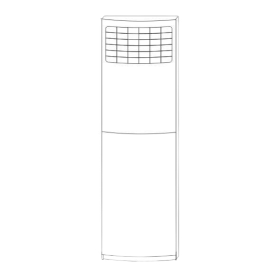
Page 6: Dimension
2. Dimension 2.1 Indoor Unit Dimension Mode (mm) (mm) (mm) 1900... -
Page 7: Outdoor Unit
2.2 Outdoor Unit Dimension Model (mm) (mm) (mm) (mm) (mm) (mm) MOI-60H-RB4W 1245 1020 MOU-60HN1-RB4W 1170 (2T0043800026) MOU-60HN1-RB4W 633.5 (2T0043800036) -
Page 8: Refrigerant Cycle Diagram
3. Refrigerant cycle diagram MOI-60H-RB4W MOU-60HN1-RB4W(2T0043800036) INDOOR OUTDOOR CHECK VALVE LIQUID SIDE (Heating Model only) 2-WAY VALVE T3 Condenser temp. sensor CAPILIARY TUBE HEAT EXCHANGE HEAT (EVAPORATOR) T1 Room temp. EXCHANGE sensor (CONDENSER) T2 Evaporator temp. sensor GAS SIDE 4-WAY VALVE High pressure switch 3-WAY VALVE Accumulator... -
Page 9: Wiring Diagram
4. Wiring diagram 4.1 MFE-60AMN1-RB4W Indoor Unit Outdoor Unit... -
Page 10: Mfe-60Arn1-Rb4W(2T0043800026)
4.2 MFE-60ARN1-RB4W(2T0043800026) Indoor Unit Outdoor Unit... -
Page 11: Mfe-60Arn1-Rb4W(2T0043800036)
4.3 MFE-60ARN1-RB4W(2T0043800036) Indoor Unit Outdoor Unit... -
Page 12: Installation Details
5. Installation details 5.1 Installation place 5.1.1 Indoor Unit a.Ensure the spaces indicated by arrows from the wall, ceiling, fence or other obstacles. b.There should not be any heat source or steam near the unit. c.There should not be any obstacles blocking the air circulation. d.A place where air circulation in the room is good. -
Page 13: Installing
it may cause trouble for air-flow shortage. 5.1.2.3 Reserve enough space for installation, maintenance and unit-functioning. Remove as many obstacles as possible nearby. Caution: Installation in the following places may cause trouble. If it is unavoidable to use in such places,please consult with the dealer. - Page 14 2. Dismounting the air-inlet grid Please take off the air-inlet grid before connecting the pipes/wires. Pull down the two knobs marked "PULL" on the grid, take off the two straps, then the air-inlet grid goes free. 3. Take the Pipe Clip off before connecting the pipes and wiring; fit it when these finished. Use accessories to connect the pipes/wires on both sides and back side.
- Page 15 5.2.2 Outdoor Unit: 1. Ship the a/c to the installation place originally packed; 2. Be careful while hanging the unit because the center of gravity of the unit is not centralized; 3. Do not make the angle of inclination more than 45 degrees while shipping;(Avoid horizontal storage) 4.
-
Page 16: Refrigerant Pipe Connection
For the value of A and B, please refer to the dimension part. 5.3 Refrigerant pipe connection 5.3.1 Pipe length and the elevation The correct refrigerant quantity filled in the 5-meter-long pipe of the outdoor unit is marked on the Product Data Plate. If you have to use longer pipe for every meter plus pipe, the refrigerant should be added according to the following calculation. - Page 17 5.3.2 Piping connection 5.3.2.1 Connecting Of Refrigerant Pipe a) Only the correctly installing of indoor and outdoor unit done, can the refrigerant pipe be connected. b) The cut-off valves are completely close before ex-work. Before connecting the refrigerant pipe, be careful to check whether the valves are completely close. c) The connecting procedure of refrigerant pipe: first, unscrew the two valves on the outdoor unit and the pipe-jointing nut on the indoor unit(please keep them carefully).
- Page 18 d. The bendable pipe may not be bent for more than 3 times. Bend the thin pipe a. While bending, expose the pipe by cutting the concave gap on the bending heat-insulation pipe(roll it with soft band after bent). b. To avoid pipe deformation, the radius is the bigger the better. c.
- Page 19 Additional Outside diameter Torque tightening torque inch N.cm N.cm Ф12.7 4950 6030 Ф19 9720 11860 5.3.3 Installation for the first time Air and moisture in the refrigerant system have undesirable effects as below: ● Pressure in the system rises. ● Operating current rises. ●...
- Page 20 1. Air purging with vacuum pump (Indoor unit) (Outdoor unit) (Liquid side) Two-way valve Close (Gas side) Three-way valve Close Manifold valve Compound meter Pressure gauge -0.1MPa Handle Lo Handle Hi Charge hose Charge hose Vacuum pump Vacuum pump 1) Completely tighten the flare nuts of the indoor and outdoor units, confirm that both the 2-way and 3-way valves are set to the closed position.
- Page 21 after the gas coming out, then tighten the flare nut again. Make sure the pressure display in the pressure indicator is a little higher than the atmosphere pressure. Then remove the charge hose from the 3 way valve. 8) Fully open the 2 way valve and 3 way valve and securely tighten the cap of the 3 way valve.
- Page 22 the flare nut on the 2-way valve approximately 45’ until the gauge indicates 0.3 to 0.5 Mpa. 6). Disconnect the charge set and the charging cylinder, and set the 2-way and 3-way valves to the open position. Be sure to use a hexagonal wrench to operate the valve stems. 7).
- Page 23 3) Put the charging cylinder onto the electronic scale and record the weight. 4) Operate the air conditioner at the cooling mode. 5) Open the valves (Low side) on the charge set and charge the system with liquid refrigerant. 6).When the electronic scale displays the proper weight (refer to the table), disconnect the charge hose from the 3-way valve’s service port immediately and turn off the air conditioner before disconnecting the hose.
- Page 24 2). Purge the air from the charge hose. Open the valve at the bottom of the cylinder and press the check valve on the charge set to purge the air (be careful of the liquid refrigerant). 3) Put the charging cylinder onto the electronic scale and record the weight. 4) Operate the air conditioner at the cooling mode.
- Page 25 1). Confirm that both the 2-way and 3-way valves are set to the opened position Remove the valve stem caps and confirm that the valve stems are in the opened position. Be sure to use a hexagonal wrench to operate the valve stems. 2).
- Page 26 2). Connect the charge set and a charging cylinder to the service port of the 3-way valve Leave the valve on the charging cylinder closed. 3). Air purging. Open the valves on the charging cylinder and the charge set. Purge the air by loosening the flare nut on the 2-way valve approximately 45’...
- Page 27 Procedure: 1). Confirm that both the 2-way and 3-way valves are set to the opened position. 2). Connect the vacuum pump to 3-way valve’s service port. 3). Evacuation for approximately one hour. Confirm that the compound meter indicates -0.1Mpa. 4). Close the valve (Low side) on the charge set, turn off the vacuum pump, and confirm that the gauge needle does not move (approximately 5 minutes after turning off the vacuum pump).
- Page 28 2. Refrigerant charging Electronic scale Procedure: 1). Connect the charge hose to the charging cylinder, open the 2-way valve and the 3-way valve Connect the charge hose which you disconnected from the vacuum pump to the valve at the bottom of the cylinder. If the refrigerant is R410A, make the cylinder bottom up to ensure liquid charge.
-
Page 29: Drain Pipe Of The Indoor Unit
minute and then repeat the procedure. 5).When the electronic scale displays the proper weight, disconnect the charge hose from the 3-way valve’s service port immediately If the system has been charged with liquid refrigerant while operating the air conditioner, turn off the air conditioner before disconnecting the hose. 6). -
Page 30: Wiring
5.5 Wiring Please refer to the Wiring Diagram. Note: The power supply of the air conditioner is different according to the models. Please refer to the WIRING DIAGRAM pasted on the indoor and outdoor units befo re wire connection. 5.6 Test run 1. -
Page 31: External View And Display
6. External view and display 6.1 Parts names This unit consists of indoor unit and outdoor unit. Note: All the pictures in this manual are for explanation purpose only. They may be slightl y different from the air conditioner you purchased(depend on model). The actual sh ape shall prevail. -
Page 32: Control Panel
6.2 Control panel On/Off button: Power-on and power-off the A/C(Air conditioner) LED indicator :Lights when unit runs normally ,flashes one time per second when the unit is waiting for orders ,flashes two times per second when the unit is sick. Mode select button : Use this button to select among the following 5 modes : Auto :automatically adjust the temperature (17~30℃) Cool :normal cooling operation(17~30℃) -
Page 33: Led
Time adjusting button: ‘Hour’: set the hour of current time ‘Minute’: set the minute of current time Confirm/Cancel button :Push this button to confirm or cancel the timer setting Test Running button :Push this button to make the unit run for an hour of test ,this function is specially designed for maintenance technicians. -
Page 34: Operation Characteristics
7. Operation characteristics Mode Cooling Drying Heating operation Temperature operation operation Room temperature 17℃~32℃ 0℃~30℃ 17℃~32℃ 18℃~43℃ (-7℃~43℃: For the models Outdoor temperature -7℃~24℃ 18℃~ 43℃ with low temperature cooling system) CAUTION: 1. If air conditioner is used outside of the above conditions, certain safety protection features may come into operation and cause the unit to function abnormally. -
Page 35: Electronic Function
8. Electronic function 8.1 Main data introduction Ts : Set temperature, T1 : Room temperature T2: Evaporator pipe temperature T3: Condenser pipe temperature T4: Outdoor ambient temperature 8.2 Main Protection 8.2.1 Time delay for the compressor start-up At the beginning of energizing or after the stop of the compressor, certain time delay will be needed to start the compressor. -
Page 36: Operation Modes And Functions
8.3.2.1 Four-way valve opens at once and anti-cold air function opens at the same time, electric heaters starts or stops according to 8.3.2.4. 8.3.2.2 Condition for the compressor and outdoor fan action: MFE-60ARN1-RB4W(2T0043800036) Condition Compressor and outdoor fan Ts-T1≥1° C T1-Ts>0°... - Page 37 Fan speed Ts-T1≥4° C High 2° C≤Ts-T1 < 4° C Ts-T1 < 2° C 8.3.2.4 Electric heaters (only available to some modes) Electric heaters only opens in heating mode MFE-60ARN1-RB4W(2T0043800036) Condition Electric heaters T4<5℃ T4>7℃ The others modes: Condition Electric heaters Ts-T1 >...
- Page 38 calculate time again). (3) Accumulated time when temperature of outdoor heat exchanger coil T3 is below 3° C reaches to 80 minutes, then consecutive 3 minutes less than -2 degrees (Just for the AC is turn on , whether or not the heating mode the temperature was detected, start to statistical time when reach the temperature condition .
- Page 39 (1)Time of defrosting lasts 10 minutes. (2) Temperature of outdoor coil T3 is up to 20° C. 8.3.2.6 High evaporator coil temp.T2 protection: Model MFE-60AMN1-RB4W MFE-60ARN1-RB4W (2T0043800026) MFE-60ARN1-RB4W (2T0043800036) 8.3.3 Cooling mode 8.3.3.1 Conditions for the compressor and outdoor fan action...
- Page 40 When T3≤30℃, the above fan is on, the below fan is off. 8.3.3.2 Action of Indoor Fan HIGH/ MED /LOW/AUTO fan can be switched over by your comfort. Auto fan under cooling mode. MFE-60ARN1-RB4W(2T0043800036) High Medium The others modes: Condition Fan speed T1-Ts≥4°...
- Page 41 When T2≤-1℃ and lasts for 4 minutes, the indoor has no capacity demand and resume till T2≥10℃. 8.3.3.4 Condenser high temperature T3 protection When T3≥T3CoolStop_ADD℃ for 3 seconds, the compressor will shut off. When T3< T3CoolRts_ADD℃,the compressor will restart. Model T3CoolStop_ADD T3CoolRts_ADD MFE-60AMN1-RB4W MFE-60ARN1-RB4W (2T0043800026) MFE-60ARN1-RB4W...
- Page 42 8.3.4.2 Four-way valve is closed, the compressor and outdoor fan will operate the same as in cooling mode. 8.3.5 Auto Mode MFE-60ARN1-RB4W (2T0043800036): 8.3.5.1. Under auto mode, the indoor fan is set to be auto. 8.3.5.2 When entering auto mode, the heating, fan only or cooling operation will be automatically chosen according to the room temperature T1 and the set temperature Ts.
-
Page 43: Other Functions
Mode, Set temperature, fan speed, time, timer, etc. 8.4.2 Timer The machine should be provided with max. Interval of 24h. 9. Trouble shooting 9.1 Self-diagnosis MFE-60ARN1-RB4W (2T0043800036): Codes Contents Protection of temperature of indoor evaporator Protection of temperature of outdoor condenser... -
Page 44: Leds For The Indication Of Outdoor Trouble
9.2 LEDs for the indication of outdoor trouble In normal operation, LEDs emit no light and they will flash at a frequency of 2Hz w hen trouble occurs. Their codes are listed in the following table: MFE-60ARN1-RB4W (2T0043800036): LED2(green) LED3(yellow) LED4(red) Type... -
Page 45: Troubles And Solutions
Trouble Lack of phase(C) Trouble Protection of low pressure Flash Flash Trouble Overload of current Flash Trouble Communication malfunction Flash Flash Open- or short-circuit of T3 temperature sensor Trouble Flash Flash Open- or short-circuit of T4 or T5 temperature sensor or Trouble Flash rotection of high pressure... - Page 46 9.3.1 Open or short circuit of temperature sensor Open or short circuit of temperature sensor Check the connections between temperature Correct the connections. sensor and PCB. Are the connections good? Check the resistance value of the sensor via Appendix 1 Is it normal? Replace indoor or outdoor PCB.
- Page 47 9.3.3 Phase sequence error Phase sequence error Change the order of the wires to power supply. Switch on the unit again. If the problem cannot be solved, the outdoor PCB is defective 9.3.4 High temperature protection of condenser High temperature protection of condenser Check the resistance of the temp.
- Page 48 9.3.5 High pressure protection 9.3.6 Low temperature protection Low temperature protection Possible reason 1: The outdoor ambient temp. is low. 2: The wires are loose to the temp. sensor. 3: The temp. sensor is defective. 4: The evaporator or the filter is dirty. 5: System has block.
- Page 49 9.3.8 Overload of current...
- Page 50 9.3.9 Indoor / outdoor unit communication error...
- Page 51 Power off, then turn on the unit 5 seconds later(reconnect the power wire).Is the error still displaying after several minutes? Check all the wirings between indoor and outdoor, indoor PCB and outdoor PCB following the wiring diagram. Are all the wirings connected correctly? Measure Vs, is it moving alternately between positive value and negative...
- Page 52 9.3.10 Refrigerant Leakage Detection Shut off the power supply and turn it on 5 seconds later. Is it still displaying the error code? Check if T2 sensor is well Is there cool air blowing fixed. Correct the installation or replace T2 sensor. Does out from indoor air outlet? the problem remain again? Is there any leakage? Especially...
- Page 53 9.3.11 Indoor fan speed has been out of control Shut off the power supply and turn it on 5 seconds The unit operates normally. later. Is it still displaying the error code? Find out the cause and have it solved. For Shut off the power supply, example, check rotate the fan by hand.
- Page 54 Index 1: 1 DC Fan Motor(control chip is in PCB) Color Orange Grey White Pink Black Signal Color Blue Yellow Signal 1) Release the UVW connector. Measure the resistance of U-V, U-W, V-W. If the resistance is not equal to each other, the fan motor must has problems and need to be replaced.
- Page 55 9.3.12 Temperature protection of compressor discharge Temperature protection of compressor discharge Check whether the Check whether the compressor discharge temp. Stop leaking and add refrigerant refrigerant is leak is more than 115° C ? Check whether the wiring connection is right between compressor discharge temp.
- Page 56 Appendix Temp. Sensor Resistance Value Table (℃--K) ℃ ℃ ℃ ℃ K Ohm K Ohm K Ohm K Ohm 115.266 12.6431 2.35774 0.62973 108.146 12.0561 2.27249 0.61148 101.517 11.5000 2.19073 0.59386 96.3423 10.9731 2.11241 0.57683 89.5865 10.4736 2.03732 0.56038 84.2190 10.000 1.96532 0.54448...
- Page 57 Appendix 2 Unit: ℃---K Discharge temp. sensor table 542.7 68.66 13.59 3.702 511.9 65.62 13.11 3.595 62.73 12.65 3.492 455.9 59.98 12.21 3.392 430.5 57.37 11.79 3.296 406.7 54.89 11.38 3.203 384.3 52.53 10.99 3.113 363.3 50.28 10.61 3.025 343.6 48.14 10.25 2.941...