Table of Contents
Advertisement
Advertisement
Table of Contents

Related Manuals for Iridium 9522B


Summary of Contents for Iridium 9522B
- Page 1 9 5 2 2 B L -Ban d T r an s cei ve r P r o d u c t In f o rm a t io n G u id e Iridium Satellite LLC Toll Free: +1.866.947.4348 [US Only] 6701 Democracy Blvd., Suite 500...
-
Page 2: Table Of Contents
G P S F e e d T h r o u g h Specification ............. 17 4.6.3 Radio Characteristics ..................18 Instructions for the s afe Installation a nd us e of t he 9522B LB T ....19 Instructions for t he Integrator ................. 19 Instructions from the integrator to the user..............19 Modem Commands and Configuration................ -
Page 3: Revision History
Iridium Satellite LLC 9522B L-Band Transceiver Product Information Guide Revision History Revision Date Comment V0.1 First revision based on 9522A product information guide V0.2 17 April 2008 Updated mechanical drawings, mass and power. V0.3 22 May 2008 Updated Header and DC Power Input Specification V0.4... -
Page 4: Product Overview
9522B to be used in place of the 9522A. A pass thru connector is provided to allow a GPS receiver to share the same antenna as the 9522B LBT. The 9522B is regulatory approved for FCC, Canada, and CE assuming an antenna with a gain of ~3dBi. -
Page 5: Standards Compliance
2.1 FCC Compliance The 9522B is certified under 47 CFR Part 25 as FCC ID: Q639522B. It also complies with Part 15 of the FCC Regulations. Operation is subject to the condition that this device does not cause harmful interference. -
Page 6: Physical Specifications
Storage Humidity Range ≤ 93% RH The 9522B LBT may additionally be operated up to +70ºC only if it is mounted in a location that is inaccessible to the user. The unit must have adequate ventilation - if this is not done the surface of the unit may become hot enough to cause burns. -
Page 7: Dimensions
3.2 Dimensions The overall dimensions of the 9522B LBT and its weight are summarized in Table 3 below. Dimensioned views of the 9522B LBT are shown in Figures 2-5 which follow. All dimensions are in mm unless otherwise stated. Table 3: Mechanical Dimensions... - Page 8 Iridium Satellite LLC 9522B L-Band Transceiver Product Information Guide Figure 2: Bottom (connector) View Figure 3: Back (mounting) View...
-
Page 9: Interface Connectors
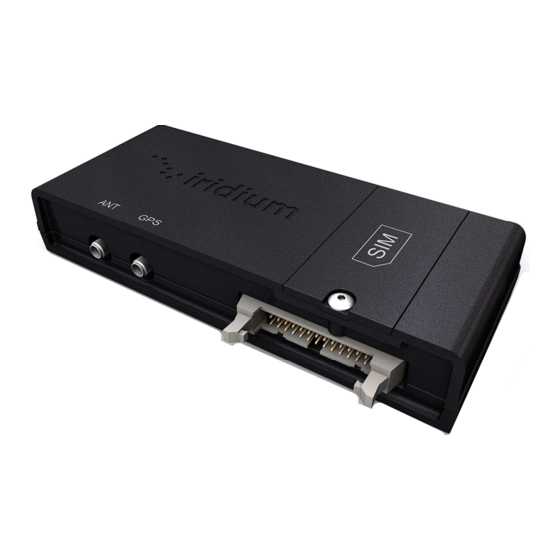
Antenna Connector (located at the left-hand end of the bottom of the 9522B LBT) • GPS Feed Through Connector (located in the middle of the bottom of the 9522B LBT) • Subscriber Identity Module (SIM) Connector (located beneath a cover plate on the front of the 9522B... -
Page 10: Multi-Interface Connector
Iridium Satellite LLC 9522B L-Band Transceiver Product Information Guide LBT) 3.3.1 Multi-Interface Connector The multi-interface connector is a standard 26-pin 0.1” pitch short latch IDC header with pins in two rows of 13. Connection to this is made using a 26-way IDC without strain relief (such as AVX/Kyocera 00 8290 026 000 0X 1 or Harting 09 18 526 7803). -
Page 11: Antenna Connector
Radiall R125.072.000 (straight) or R125.172.000 (right-angle). An adaptor is available to convert this connector to TNC to enable the 9522B to be used as a replacement for a 9522A. This port must be connected to an approved antenna, located with a clear view of the sky. If the GPS... -
Page 12: Gps Feed Through Connector
GPS receiver. Note that this signal will be de-graded during a call. 3.3.4 SIM Chip Reader An integrated SIM chip reader is provided on the 9522B LBT. This connector allows installation of the chip form of the SIM beneath a cover plate on the 9522B LBT housing. -
Page 13: Mounting
Standard NASM122238 serves as a technical reference for the recommended helical coil insert. 3.5 Mounting in Harsh Environments If the 9522B LBT is to be used in a harsh environment with exposure to high humidity, water or dust, the LBT must be installed in the correct orientation, with all connectors facing downwards. -
Page 14: Electrical Interfaces
6 below. The EXT_PWR and GND inputs are used to supply DC power to the 9522B LBT. The EXT_ON_OFF control input is pulled to a GND level to toggle the 9522B LBT on and off. Note that both pairs of pins should be connected for EXT PWR and EXT GND. -
Page 15: Control/Digital Audio Interface (Dpl Bus)
The control/digital audio interface enables peripherals such as handsets and SIM card readers to be interfaced to the 9522B LBT. The interface utilizes an Iridium Proprietary communication bus not detailed in this fact sheet. Details can be made available after appropriate Non-Disclosure and/or License Agreements are executed. -
Page 16: Analog Audio Interface
4.5 SIM Interface An integrated SIM chip reader is provided on the 9522B LBT. An external SIM card reader may also be interfaced as a peripheral to the 9522B LBT via the DPL bus (control/audio interface). A SIM card in the... -
Page 17: Rf Interface
4.6.2 G P S F e e d T h r o u g h Specification The GPS feed through connector is provided to allow an Iridium 9522B and a GPS module to share a single antenna. When used in this way, the antenna is connected to the antenna connector, described in 3.3.2 above. -
Page 18: Radio Characteristics
Iridium Satellite LLC 9522B L-Band Transceiver Product Information Guide 4.6.3 Radio Characteristics The tables within this section contain radio characteristics of the 9522B LBT. Table 10: In-Band Characteristics Parameter Value Average Power during a transmit slot (max) Average Power during a frame (typical) 0.6 W... -
Page 19: Instructions For The Safe Installation And Use Of The 9522B Lbt
As part of these instructions the installer should inform the user that they should not service the 9522B LBT. 6.0 Modem Commands and Configuration The 9522B is configured through the use of AT commands. A full listing of the supported AT commands can... -
Page 20: Installation Of The 9522B In Place Of A 9522A
7.0 Installation of the 9522B in place of a 9522A The 9522B is designed to replace the 9522A with the assistance of an optional adapter plate and cables. An adapter plate is mounted onto the 9522B and provides mounting points similar to those of the 9522A. -
Page 21: Physical Characteristics
9522B L-Band Transceiver Product Information Guide 7.1 Physical characteristics The physical design of the 9522B adapter is given in Figures 7-10 which follow. All dimensions are in mm unless otherwise stated. The TNC adapter is cable-mounted to allow flexibility in the routing of the antenna cable. -
Page 22: Power Supply
7.2 Power Supply With the adapter cables in use, the requirements for the signals to and from the 9522B are as given in section 3.3. Note that it is important to ensure that the power supply voltage measured at the 9522B multi-way connector does not fall below 4.0v.