Table of Contents
Advertisement
Quick Links
Download this manual
See also:
User Manual
Advertisement
Table of Contents

Summary of Contents for Iridium 9522A
- Page 1 P r o d uc t I nf or m a t i o n G ui de R e v i s i o n 1 . 0 1 Iridium Satellite LLC Toll Free: +1.866.947.4348 [US Only] 6701 Democracy Blvd., Suite 500 International +1.480.752.5155...
-
Page 2: Table Of Contents
Iridium Satellite LLC 9522A L-Band Transceiver Product Information Guide V1.1 032405 Contents Revision History............................2 Product Overview ..........................3 Standards Compliance ........................3 FCC Compliance ......................... 3 CE Compliance ........................... 3 Physical Specifications ........................4 Environmental ..........................4 Dimensions..........................4 Interface Connectors ........................ -
Page 3: Product Overview
Compatibility, and AC Safety in the United States, European Union and Canada. 2.1 FCC Compliance The 9522A is certified under 47 CFR Part 25 as FCC ID:Q639522A. It also complies with Part 15 of the FCC Regulations. Operation is subject to the condition that this device does not cause harmful interference. -
Page 4: Physical Specifications
≤ 93% RH Storage Humidity Range 3.2 Dimensions The overall dimensions of the 9522A LBT and its weight are summarized in Table 2 below. Dimensioned views of the 9522A LBT are shown in Figures 2-5 which follow. Table 2: Mechanical Dimensions... - Page 5 Iridium Satellite LLC 9522A L-Band Transceiver Product Information Guide V1.1 032405 Figure 3: Bottom View Figure 4: Antenna Connector End View Figure 5: Multi-Interface Connector End View...
-
Page 6: Interface Connectors
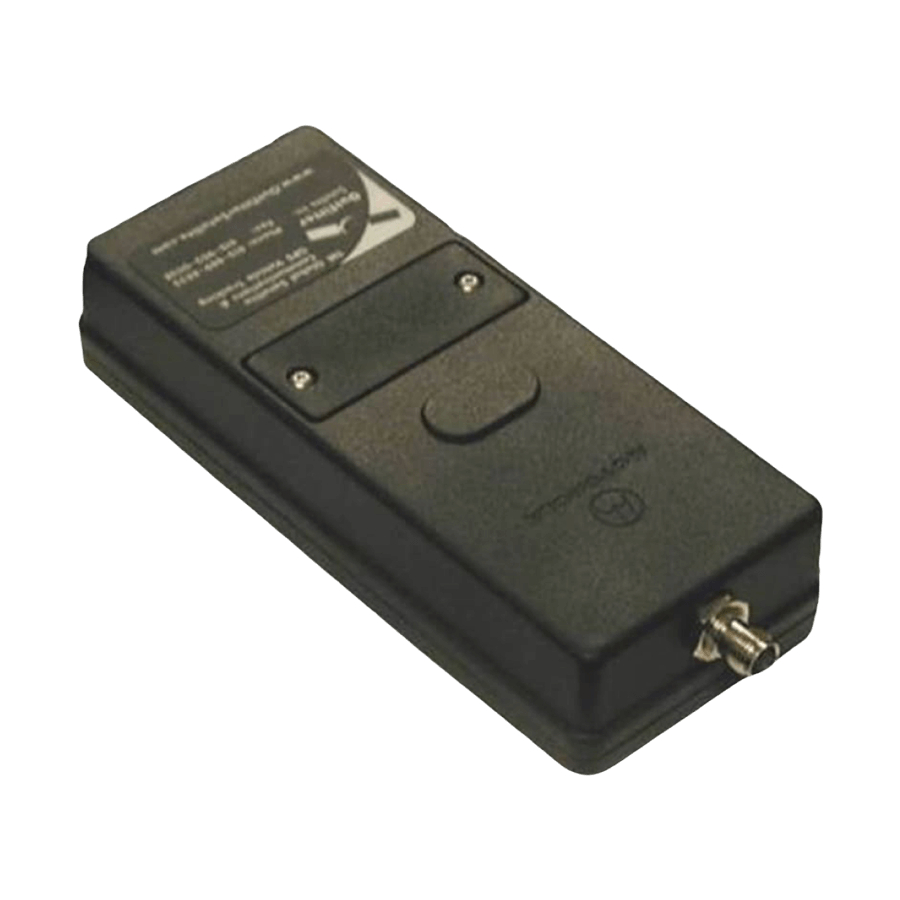
Multi-Interface Connector (located on the end of the 9522A LBT) Antenna Connector (located on the end of the 9522A LBT; opposite to the multi-interface connector) Subscriber Identity Module (SIM) Chip Connector (located beneath a cover plate atop the 9522A LBT) 3.3.1 Multi-Interface Connector... -
Page 7: Antenna Connector
3.5 Connector Sealing in Harsh Environments If the 9522A LBT is to be used in a harsh environment with exposure to high humidity or water, the mating of the multi-interface connector must be further sealed to protect from moisture entry. It is recommended t h a t a b e a d o f R T V s i l i c o n e s e a l a n t b e p l a c e d o n t h e c o n n e c t o r ma t i n g t o t h e 9 5 2 2 A L B T ’... -
Page 8: Electrical Interfaces
4 below. The EXT_PWR and GND inputs are used to supply DC power to the 9522A LBT. The EXT_ON_OFF control input is pulled to a GND level to toggle the 9522A LBT on and off. Note that both pairs of pins should be connected for EXT PWR and EXT GND. -
Page 9: Rs232 Data Interface
4.5 SIM Interface An integrated SIM chip reader is provided on the 9522A LBT. An external SIM card reader may also be interfaced as a peripheral to the 9522A LBT via the DPL bus (control/audio interface). A SIM card in the... -
Page 10: Rf Interface
Iridium Satellite LLC 9522A L-Band Transceiver Product Information Guide V1.1 032405 4.6 RF Interface 4.6.1 R F Interface Specifications The RF interface requirements for the 9522A LBT are summarized in Table 7 below. Table 7: General RF Parameters Parameter Value Frequency Range 1616 MHz to 1626.5 MHz... -
Page 11: Instructions For The Safe Installation And Use Of The 9522A Lbt
. ’ As part of these instructions the installer should inform the user that they should not service the 9522A LBT. 6.0 Modem Commands and Configuration The 9522A is configured through the use of AT commands.


