
Related Manuals for Iridium 9603


Summary of Contents for Iridium 9603
- Page 1 Iridium 9603/9603N S B D T r a n s c e i v e r Developer’s Gui de R E V I S I O N 3 . 1...
- Page 2 Revision 3.1 LEGAL DISCLAIMER AND CONDITIONS OF USE This document contains information for the Iridium 9603/9603N (“Product”) and is provided “as is.” The purpose of providing such information is to enable Value Added Resellers and Value Added Manufacturers (collectively, “Product Developer(s)”) to understand the Product and how to integrate it into a wireless solution.
- Page 3 SOFTWARE OR APPLICATIONS OR OTHER FINANCIAL LOSS CAUSED BY THE PRODUCT/SERVICE (INCLUDING HARDWARE, SOFTWARE AND/OR FIRMWARE) AND/OR THE IRIDIUM SATELLITE SERVICES, OR ARISING OUT OF OR IN CONNECTION WITH THE ABILITY OR INABILITY TO USE THE PRODUCT/SERVICE (INCLUDING HARDWARE, SOFTWARE AND/OR FIRMWARE) AND/OR THE IRIDIUM SATELLITE SERVICES TO THE FULLEST EXTENT THESE DAMAGES MAY BE DISCLAIMED BY LAW AND WHETHER ADVISED OF THE POSSIBILITIES OF SUCH DAMAGES.
-
Page 4: Revision History
Iridium 9603 SBD Transceiver Product Developers Guide Revision 3.1 Revision History Revision Date Comment 05-09-12 Iridium 9603 Initial Release 06-04-12 Iridium Commercial Release 08-06-12 Added Section 4.2.2 addressing antennae design guidance. 08-22-14 Updated to include 9603N 08-26-14 Updated FCC and IC regulatory statements based on guidance from BABT Proprietary &... -
Page 5: Table Of Contents
4.2.1 Antenna Characteristics ............................24 4.2.2 Important Design Guidance for the 9603 ......................... 24 RF Interface Specifications ............................25 Radio C h a r a c t e r i s t i c s ............................25 S-meter Performance .............................. 25 5 AT Command Set Description .................... -
Page 6: List Of Abbreviations
Abbreviation Description Conformité Européene (V.24 signal) Clear To Send. This signal is used to control the flow of data to the Iridium 9603/9603N Direct Current (V.24 signal) Data Carrier Detect Data Communications Equipment. In this Product, DCE refers to the Iridium 9603/9603N (V.24 signal) Data Set Ready. -
Page 7: Product Overview
The 9603N is a second generation version of the 9603 and is identical in form and function to the 9603. This document applies to both the 9603 and 9603N as indicated by the term ‘9603/9603N’. Where the contents of this document apply specifically to either the 9603 or 9603N then this is indicated by the use of the terms ‘9603’... -
Page 8: Transceiver Regulatory Certification
With appropriate external connections, the host system can be designed to meet full transceiver regulatory tests and sold as a Regulatory Certified product that meets CE, FCC and IC requirements. The 9603 has regulatory and technical certifications as shown in Table 1. The 9603N has regulatory and technical certifications as shown in Table 1a. -
Page 9: Software Revision
Product Developer application is designed for the Software Release loaded in the Iridium 9603/9603N SBD Transceiver. This can be read out of the module using the AT command interface. A software upgrade utility is provided with each SW release. The utility runs on a Windows compatible OS and will automatically upgrade the modem with the latest version. -
Page 10: Fcc Class B Digital Device Notice
Iridium 9603 SBD Transceiver Product Developers Guide Revision 3.1 FCC Class B Digital Device Notice This equipment has been tested and found to comply with the limits for a Class B digital device, pursuant to part 15 of the FCC Rules. -
Page 11: R&Tte Statement
Revision 3.1 1.10 R&TTE Statement Iridium Communications Inc. hereby declares that the 9603N is in compliance with the essential requirements and other relevant provisions of Directive1999/5/EC. A copy of the Declaration of Conformity is given below. Proprietary & Confidential Information... -
Page 12: Physical Specification
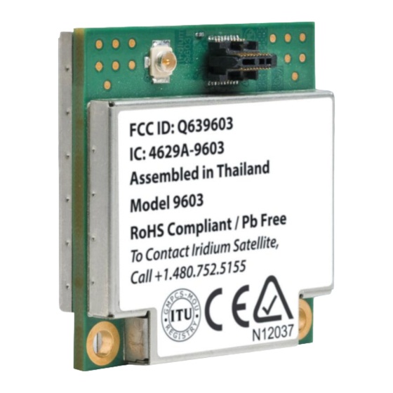
For illustrative purposes a picture of the Iridium 9603 SBD Transceiver Module* is shown in Figure 1. Figure 1. Iridium 9603 SBD Transceiver Front and Back Views *Note: The appearance of the 9603N is identical to the 9603 with the exception of the part marking on the label. Module Dimensions The overall dimensions of the Iridium 9603/9603N module and its weight are summarized in Table 2. - Page 13 Iridium 9603 SBD Transceiver Product Developers Guide Revision 3.1 Figure 2. Dimensions of the 9603/9603N Transceiver Proprietary & Confidential Information Distribution of guide restricted to product developers only • Information contained in this guide is subject to change without notice.
-
Page 14: Mechanical Dimensions - Motherboard Mounting
The Iridium 9603/9603N SBD Transceiver is provided with two mounting holes on the opposite side from the system connector. The module should be assembled onto the motherboard of the host system, by pushing the module onto matching connectors on the motherboard and then securing the two mounting holes to the motherboard using screws. - Page 15 Iridium 9603 SBD Transceiver Product Developers Guide Revision 3.1 Figure 4. Connector and Mounting Detail for the Iridium 9603/9603N Transceiver Proprietary & Confidential Information Distribution of guide restricted to product developers only • Information contained in this guide is subject to change without notice.
- Page 16 PCB layout or mechanical arrangement. The 9603/9603N is designed to be incorporated within a host system. As such, the antenna or cable distribution system that feeds the host system should be terminated in a robust RF connector that is suitable for the end-application.
-
Page 17: Environmental
Iridium 9603 SBD Transceiver Product Developers Guide Revision 3.1 Environmental 2.3.1 Environmental Specification The environmental specifications of the final Iridium 9603/9603N Transceiver Module are summarized in Table 5 below. Table 5: Environmental Specifications Parameter Value Operating Temperature Range* -30ºC to + 85ºC ≤... -
Page 18: Electrical Interfaces
Iridium 9603 SBD Transceiver Product Developers Guide Revision 3.1 3 Electrical Interfaces The following subsections contain information for the electrical interfaces of the 9603/9603N SBD Transceiver for the non-RF connections. The RF interfaces are covered in section 4 4. User Connector The user connector provides the following connections to the 9603/9603N module: ... -
Page 19: User Connector Pin Allocation
SUPPLY_OUT Output output 5mA maximum * Note: This is the supply voltage range of the 9603; the 9603N has an extended supply voltage range of +5 V +/- 0.5 V Table 8: Limits for 3.3V Digital Signals Parameter Symbol Unit... -
Page 20: Dc Power Interface
The DC power interface is comprised of the DC power inputs and a control signals as summarized in Table 7. The +5V Inputs and 0V supply returns are used to supply DC power to the 9603/9603N and ensure that enough current can be drawn across the connector without the 9603/9603N malfunctioning during transmit due to lack of current supply. - Page 21 * Note: The average power consumption will vary depending on the view of the satellite constellation from the antenna. ** Note: Includes Tx Burst droop. This is the supply voltage range of the 9603; the 9603N has an extended supply voltage range of +5 V +/- 0.5 V...
-
Page 22: Power On/Off Control
If this line is not required then it must be connected directly to the +5 V supply. Note that this on/off control is similar to the Iridium 9601 and 9602 products, but it is not the same as the 9522, 9522A or 9522B products. -
Page 23: Serial Data Interface
DC Supply Indicator Output A DC supply indicator signal is provided by the 9603/9603N which could be used directly for driving an LED to provide a visible indication that the Transceiver supply is on. Alternatively the output signal could be used in application logic to determine if the internal Transceiver power supply is on. -
Page 24: Rf Interface
Important Design Guidance for the 9603 The 9603* requires a load, i.e. antenna plus cable, to present a VSWR of less than 3:1 over the frequency range of 1.2 GHz to 2.0 GHz at the 9603 RF connector. This is the out-of-band VSWR requirement. In the event a particular antenna design does not meet the out-of-band VSWR requirement, a combination of cable loss and passive attenuation, i.e. -
Page 25: Rf Interface Specifications
AT commands and responses. Note that versions 3.2 and earlier of the ISU AT Command Reference do not mention the 9603/9603N. Subsequent versions of the reference will do so. At the time of writing of this version of this document, all information contained in the ISU AT Command Reference for the 9602 applies equally to the 9603/9603N.