Table of Contents
Advertisement
Quick Links
Iridium 9602/9602N SBD Transceiver
Iridium Satellite LLC
1750 Tysons Boulevard, Suite 1400
McLean, VA 22102 USA
www.iridium.com
Proprietary & Confidential Information
Distribution of guide restricted to product developers only. • Information contained in this guide is subject to change without notice.
Toll Free: +1.866.947.4348 [US Only]
International +1.480.752.5155
email: info@iridium.com
D e v e l o p m e n t G u i d e
M A N 0 0 1 7
Advertisement
Table of Contents

Related Manuals for Iridium 9602


Summary of Contents for Iridium 9602
- Page 1 Iridium 9602/9602N SBD Transceiver D e v e l o p m e n t G u i d e M A N 0 0 1 7 Iridium Satellite LLC 1750 Tysons Boulevard, Suite 1400 Toll Free: +1.866.947.4348 [US Only] McLean, VA 22102 USA International +1.480.752.5155...
- Page 2 ("Iridium") assume no responsibility for any typographical, technical, content or other inaccuracies in this document. Iridium reserves the right in its sole discretion and without notice to you to change this Specification and materials and/or revise this document or withdraw it at any time. The Iridium Partner assumes any and all risks of using this Specification and any information provided in this Specification.
-
Page 3: Revision History
IC warning statements (sections 1.4 and 1.5) Modified Figure 4 “Example host system motherboard footprint showing 14-Apr-12 mounting position of 9602” to show the hole size and position tolerances that should be used to make a 9602 motherboard 20-Aug-12 Updated section “Legal Disclaimer and Conditions of Use”. -
Page 4: Table Of Contents
Iridium Communications Inc. 9602 SBD Transceiver Product Developers Guide Revision 5` Contents Revision History .................. 3 Contents ..................4 List of Abbreviations ................6 Product Overview ................7 Key Features ................7 Transceiver Packaging and Regulatory Certification ....... 8 Software Revision ..............10 Unauthorised Changes .............. - Page 5 Iridium Communications Inc. 9602 SBD Transceiver Product Developers Guide Revision 5` Hardware Failure Reporting ............28 Network Available Output ............. 28 DC Supply Indicator Output ............29 RF Interface ................. 29 RF Connector Types ..............29 ANT Connector ................29 4.2.1...
-
Page 6: List Of Abbreviations
Data Communications Equipment. In this Product, DCE refers to the Iridium 9602/9602N (V.24 signal) Data Set Ready. This signal, from the Iridium 9602/9602N, indicates readiness to accept communication over the data port Data Terminal Equipment. In this Product, DTE refers to the FA (V.24 signal) Data Terminal Ready. -
Page 7: Product Overview
The 9602N is a second generation version of the 9602 and is identical in form and function to the 9602. This document applies to both the 9602 and 9602N as indicated by the term ‘9602/9602N’. Where the contents of this document apply specifically to either the 9602 or 9602N then this is indicated by the use of the terms ‘9602’... -
Page 8: Transceiver Packaging And Regulatory Certification
Regulatory Certified product that meets CE, FCC and IC requirements. The 9602 is tested to the regulatory and technical certifications shown in Table 1 (See Note below). The 9602N has regulatory and technical certifications as shown in Table 1a. - Page 9 Iridium Communications Inc. 9602 SBD Transceiver Product Developers Guide Revision 5` Table 1a: 9602N Regulatory and Technical Certifications. Electrical / Regulatory Mechanical / Radio Tests EMC Tests Approvals Operational Safety Tests ETSI EN 301 441 V1.1.1 ETSI EN 301 489-1 V1.9.2 (2011)
-
Page 10: Software Revision
Product Developer application is designed for the Software Release loaded in the 9602/9602N SBD Transceiver. This can be read out of the module using the AT command interface. A software upgrade utility is provided with each SW release. The utility runs on a Windows compatible OS and will automatically upgrade the modem with the latest version. -
Page 11: Rf Exposure
Iridium Communications Inc. 9602 SBD Transceiver Product Developers Guide Revision 5` 1.6 RF Exposure This equipment complies with FCC and IC radiation exposure limits set forth for an uncontrolled environment. The antenna should be installed and operated with minimum distance of 20 cm between the radiator and your body. -
Page 12: Labelling Requirements For The Host Device
"Contains", or similar wording expressing the same meaning, as follows: 9602 Contains FCC ID: Q639602 or Contains transmitter module FCC ID: Q639602 Contains IC: 4629A-9602 or Contains transmitter module IC: 4629A-9602 9602N Contains FCC ID: Q639603N or Contains transmitter module FCC ID: Q639603N Contains IC: 4629A-9603N or Contains transmitter module IC: 4629A-9603N L'appareil hôte doit être étiqueté... -
Page 13: R&Tte Statement
Revision 5` 1.10 R&TTE Statement Iridium Communications Inc. hereby declares that the 9602N is in compliance with the essential requirements and other relevant provisions of Directive1999/5/EC. A copy of the Declaration of Conformity is given below. Proprietary & Confidential Information... -
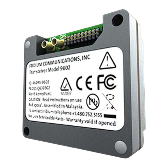
Page 14: Physical Specification
For illustrative purposes a picture of the Iridium 9602 SBD Transceiver Module is shown in Figure 1. Figure 1 Iridium 9602 SBD Transceiver Front and Back Views *Note: The appearance of the 9602N is identical to the 9602 with the exception of the part marking on the label. - Page 15 Figure 2 General Assembly and Dimensions of the 9602/9602N SBD Transceiver Module (Not to scale, dimensions in millimeters) This drawing shows some of the key dimensions within the 9602/9602N specify the mechanical position of its connectors with respect to its mounting holes.
-
Page 16: Mechanical Dimensions - Motherboard Mounting
The 9602/9602N SBD Transceiver is provided with two mounting holes, one at each diagonal corner. The module should be assembled onto the motherboard of the host system, by pushing the module onto matching connectors on the motherboard and then securing the diagonal mounting holes to the motherboard using mechanical fasteners. - Page 17 Iridium Communications Inc. 9602 SBD Transceiver Product Developers Guide Revision 5` Figure 4 Example host system motherboard footprint showing mounting position of 9602/9602N (Not to scale. Dimensions in millimeters) Proprietary & Confidential Information Distribution of guide restricted to product developers only. • Information contained in this guide is subject to change without notice.
- Page 18 PCB layout or mechanical arrangement. 2. The 9602/9602N is designed to be incorporated within a host system. As such, the antenna or cable distribution system that feeds the host system should be terminated in a robust RF connector that is suitable for the end-application.
-
Page 19: Environmental
-40ºC to + 85ºC Storage Humidity Range ≤ 93% RH 2.3.2 Environmental Tests Performed The 9602 complies with the specifications listed in Table 6. The 9602N complies with the specifications listed in Table 6a. Table 6: 9602 Environmental Tests Test Name... -
Page 20: Physical Interface Connectors
The physical characteristics of the connectors and their electrical interfaces are described in more detail in Sections 3.1.1 and 4.1 respectively. 3 Electrical Interfaces The following subsections contain information for the electrical interfaces of the 9602/9602N SBD Transceiver for the non-RF connections. The RF interfaces are covered in section 0. 3.1 User Connector The user connector provides the following connections to the 9602/9602N module: •... -
Page 21: User Connector Type
9602 SBD Transceiver Product Developers Guide Revision 5` 3.1.1 User Connector Type The connector on the 9602/9602N is a Samtec low-profile header connector, part number FTSH-110-01-L-DV. This connector provides the ability for a stackable board to board configuration, allowing connection to the host system motherboard. - Page 22 This view is for illustrative purposes only. This view designation is when looking into the user connector towards the 9602/9602N module. The numbers indicate pin designation. Additionally, on the 9602/9602N PCB, pin 1 on the user connector is indicated on the board silkscreen.
-
Page 23: Dc Power Interface
The DC power interface is comprised of the DC power inputs and a control signals as summarized in Table 7. The +5V Inputs and 0V supply returns are used to supply DC power to the 9602/9602N and ensure that enough current can be drawn across the connector without the 9602/9602N malfunctioning during transmit due to lack of current supply. -
Page 24: Power On/Off Control
3.2.1 Power On/Off Control An external on/off input is provided on a pin of the User connector. The 9602/9602N starts up when power is applied and the power on/off input is high. As long as the input voltage is applied, logic high on this line turns the transceiver on and a logic low turns it off. -
Page 25: Serial Data Interface
3.3 Serial Data Interface The Serial data interface is used to both command the 9602/9602N and transfer user data to and from the Transceiver. The 9602/9602N presents a 9-wire data port to the FA (Field Application), where the interface is at 3.3V digital signal levels. - Page 26 DCD is driven OFF at all times. Note that the Ring Indicator (RI) pin is used by the 9602/9602N SBD Transceiver to indicate that a Mobile Terminated SBD (MT-SBD) message is queued at the Gateway. The Field Application can monitor this pin and use appropriate AT Commands to command the Transceiver to retrieve the MT-SBD message.
-
Page 27: Configuration Settings
RTS input ignored and the CTS output driven ON (low). When in SBD data mode, the 9602/9602N is transferring binary or text SBD message data to or from the DTE. In SBD data mode: •... -
Page 28: Serial Port Signal Levels
3.3.4.2 Data Port Outputs The five outputs from the 9602/9602N serial port (DCD, DSR, CTS, RI and RXD) are all at 3.3V digital levels. 3.4 Hardware Failure Reporting If the 9602/9602N detects a hardware problem during initialisation, the 9602/9602N may be unable to function correctly. -
Page 29: Dc Supply Indicator Output
3.6 DC Supply Indicator Output A DC supply indicator signal is provided by the 9602/9602N which could be used directly for driving an LED to provide a visible indication that the Transceiver supply is on. Alternatively the output signal could be used in application logic to determine if the internal Transceiver power supply is on. -
Page 30: Antenna Characteristics
The GPS receive path is temporarily switched off during transmissions from the 9602/9602N. As long as the 5V supply to the 9602/9602N is connected and the DC voltage on the GPS connector is present, the GPS pass-through path is made available. The GPS path is available even when the 9602/9602N module has been turned off using its ON/OFF control signal. -
Page 31: Radio Interface Specifications
Iridium Communications Inc. 9602 SBD Transceiver Product Developers Guide Revision 5` Figure 7: Equivalent circuit for GPS connection when GPS path is active and 9602/9602N is not transmitting 4.4 Radio Interface Specifications The RF interface requirements for the 9602/9602N are summarized in Table 12 below. -
Page 32: Radio Characteristics
5. If the reading is near the decision threshold it would be easy to see a 1 bar difference 5 AT Command Set Description The 9602/9602N is configured and operated through the use of AT commands. See the “ISU AT Command Reference” for the full set of AT commands and responses. For differences in AT command support between 9602/9602N software releases, see the relevant software release notes, which are made available to authorized Iridium VARs and VAMs on the Iridium Developer Extranet.