
Related Manuals for Iridium 9523


Summary of Contents for Iridium 9523
- Page 1 Iridium 9523 Product Developer's Guide I r i d i u m C o m m u n i c a t i o n s , I n c . P r o p r i e t a r y & C o n f i d e n t i a l I n f o r m a t i o n...
- Page 2 (“Iridium”) assume no responsibility for any typographical, technical, content or other inaccuracies in this document. Iridium reserves the right in its sole discretion and without notice to you to change Product specifications and materials and/or revise this document or withdraw it at any time. This...
-
Page 3: Revision History
Iridium Communications, Inc. Information Contained in this Guide Iridium 9523 Product Developer’s Guide is Subject to Change Without Notice Revision 7.0 applicable terms and conditions of such agreement(s), including without limitation software license, warranty, conditions of use and confidentiality provisions. -
Page 4: Table Of Contents
List of Abbreviations ..........................5 Product Overview ..........................6 Key Features .......................... 6 Iridium 9523 Packaging and Regulatory Certification ............6 FCC Warning Statement ......................7 Industry Canada Warning Statement ..................7 ... -
Page 5: List Of Abbreviations
Data Communications Equipment. In this Product, DCE refers to the Iridium 9523 (V.24 signal) Data Set Ready. This signal, from the Iridium 9523, indicates readiness to accept communication over the data port Data Terminal Equipment. In this Product, DTE refers to the FA (V.24 signal) Data Terminal Ready. -
Page 6: Product Overview
The Iridium 9523 is tested to the regulatory and technical certifications shown in Table 1. The 9523 is certified as a module for non-portable applications – i.e. those that do not combine the 9523 with another radio element and have an intended separation distance of over 20 cm from a person. -
Page 7: Fcc Warning Statement
Iridium Communications, Inc. Information Contained in this Guide Iridium 9523 Product Developer’s Guide is Subject to Change Without Notice Revision 7.0 EN61000-4-2 : 1995/A2 : 2001 Part 4.2 EN61000-4-3 : 2002 Part 4.3 FCC CFR47 parts 2, 15, and 25 EN61000-4-4 : 2004 EN61000-4-6 : 1996/A1 : 2001 Part 4.6... -
Page 8: Software Revision
Product Developers should read this document in conjunction with the “Software Release Notes” relevant to the revision of the software that is loaded into their Iridium 9523. The software release notes are available on the Iridium for Partners section of the Iridium.com website. - Page 9 Iridium Communications, Inc. Information Contained in this Guide Iridium 9523 Product Developer’s Guide is Subject to Change Without Notice Revision 7.0 [11] ETS 300 515: Digital Cellular Telecommunications System (Phase 2) (GSM); Call Forwarding (CF) Supplementary Services (GSM 02.82) [12] 3GPP TS 27.007: 3...
-
Page 10: Physical Specification
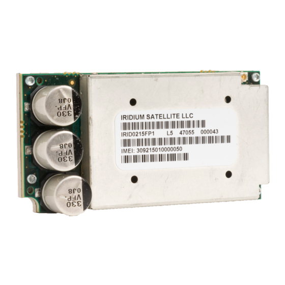
Iridium 9523 Product Developer’s Guide is Subject to Change Without Notice Revision 7.0 2 Physical Specification For illustrative purposes, pictures of the Iridium 9523, fitted with its aluminum shielding frame, are shown in Figure 1. Figure 1: Photos of Iridium 9523 Top View Bottom View Iridium Communications, Inc. -
Page 11: Dimensions And Layout
The two height values provided in Table 2 do not include the height of the compressible gasket on the bottom of the 9523 that will mate to the FA board. It is assumed that this gasket will compress to near zero thickness if screws are torqued sufficiently. -
Page 12: Field Application Board Mounting
Figure 2: Dimensions of the Iridium 9523 (Dimensions in millimeters) 2.2 Field Application Board Mounting The 9523 is designed to be mounted to an FA board as illustrated in Figure 3. Iridium Communications, Inc. Distribution of Guide Restricted Proprietary & Confidential Information... - Page 13 In Figure 4, area ‘A’ of the FA board sits under sensitive analog circuitry on the 9523’s bottom side, and it is essential that no components or tracks on the FA board appear in this area; it must be filled entirely with a solid ground plane on the top layer of the FA board.
- Page 14 Subject to Change Without Notice Revision 7.0 The FA board must provide a sufficient margin free of conductive elements around the 9523 perimeter in order to avoid electrical shorts with the 9523. This is indicated by the ‘SMT Placement Keepout Zone’.
-
Page 15: Environmental
It is expected, based on testing performed on a system that incorporates the Iridium 9523, that the Iridium 9523 would pass the tests listed in Table 4. A later revision of this document will specify which of these the Iridium 9523 has been tested to in conjunction with a test interface board that offers no protection. -
Page 16: Electrical Interfaces
Data sheets on these connectors can be found at: http://www.molex.com Pin numbering schemes for the Molex connectors on the Iridium 9523 and the host FA board are shown in Figure 5 (both pictures show the pin-out when looking down onto the boards). -
Page 17: User Connector Pin Allocation
Figure 6 provides a reference for the pin designation and shows the connector’s location and rotation with respect to the corner of the Iridium 9523 board. This view is for illustrative purposes only. This view designation is when looking into the user connector towards the Iridium 9523. - Page 18 Iridium Communications, Inc. Information Contained in this Guide Iridium 9523 Product Developer’s Guide is Subject to Change Without Notice Revision 7.0 Signal direction Signal Name Signal function Signal group (WRT modem) CODEC_PCMCLK Clock PCM audio port 1 CODEC_PCMIN Data from modem...
-
Page 19: Dc Power Supply Interface
The Iridium 9523 starts up when power is applied and the TRX_ON input is high. As long as the input voltage is applied, logic high on this line turns the Iridium 9523 on and a logic low turns it off. If this line is not required then it must be connected directly to the VBAT supply. - Page 20 The current peak in the VBOOST rail lasts for 8.3ms and repeats every 90ms (this is the period of a frame in the Iridium air interface). When not transmitting, the VBOOST current returns to zero. The VBOOST current was measured when the Iridium 9523 was connected to a 27V power source that could meet its instantaneous power requirements (around 25W).
-
Page 21: Pcm Digital Audio
3.3 PCM Digital Audio The Iridium 9523 has two PCM digital audio ports, though only one of these can be in use at any time. The active port is selected using the AT+CAR command. This setup allows the FA board to provide two parallel audio paths and switch between them through software instead of hardware. -
Page 22: Port 1
UC_DATX PCM data input UC_DARX Note: the data signal names on Port 2 are defined from the point of view of the Iridium 9523. 3.3.3 11Hz Signal for Manufacturing and Regulatory Testing An external ‘frame tick’ signal needs to be passed to the Iridium 9523 during regulatory radio testing of the host system, and possibly also during manufacturing testing. -
Page 23: Dpl Port
See the ISU AT Command Reference for further information on the data/fax interface. 3.6 SIM interface The Iridium 9523 needs an external Iridium SIM card and socket to be connected to its SIM interface. The signals operate at 3.3V logic levels, so an external SIM level converter such as the ONSemi NCN4555 must be connected between the Iridium 9523 and the SIM connector/socket to allow 3V or 1.8V SIM... -
Page 24: Transmit Power Control
External GPS Receiver Switch If the Iridium 9523 is used near a GPS receiver, it is possible that the input circuitry of the GPS receiver could be damaged by the output power of the Iridium transmitter, especially if the two devices share a single antenna. -
Page 25: Rf Interface
Additional information can be found at: http://www.i-pex.com Note that the RF connector on the Iridium 9523 is not mounted directly to the FA board along with the user interface connector. It must be attached to the FA board through a coaxial cable. -
Page 26: Radio Characteristics
RF component between the Iridium 9523 and the antenna should not exceed 3 dB. Implementation loss higher than this will affect the Iridium link performance and quality of service. Solutions with a loss higher than 3 dB will not meet the requirements of Iridium Solution Certification. -
Page 27: At Interface
Revision 7.0 5 AT Interface The 9523 is configured and operated through the use of AT commands. See the ISU AT Command Reference for the full set of AT commands and responses. For differences in AT command support between 9602 software releases, see the relevant software release notes, which are made available to authorized Iridium VARs and VAMs on the Iridium Developer Extranet.