
Related Manuals for NCR RealPOS


Summary of Contents for NCR RealPOS
- Page 1 NCR RealPOS Presentation Scanner (7893) Release 1.0 User Guide 27355 B005-0000-1917 Issue A...
- Page 2 NCR, therefore, reserves the right to change specifications without prior notice. All features, functions, and operations described herein may not be marketed by NCR in all parts of the world. In some instances, photographs are of equipment prototypes. Therefore, before using this document, consult with your NCR representative or NCR office for information that is applicable and current.
- Page 3 Preface Audience This book is written for hardware installer/service personnel, system integrators, and field engineers. Notice: This document is NCR proprietary information and is not to be disclosed or reproduced without consent.
- Page 4 References NCR RealPOS Presentation Scanner (7893)Hardware Service Guide (B005-0000-1918) NCR RealPOS Scanner Tool Suite Guide (B005-0000-1883) NCR RealPOS Scanners Safety and Regulatory Information (B005-0000-1699)
-
Page 5: Table Of Contents
Table of Contents Chapter 1: Introduction Using the Scanner......................1-1 Chapter 2: Product Information Physical Considerations ....................2-1 Environmental Considerations ..................2-2 Power Considerations....................2-2 Features and Options ....................2-3 Scanning Performance ..................2-3 Communications Protocol...................2-3 Autodiscrimination .....................2-4 USB Peripheral Port and Main (POS) Communication Port ......2-5 Operator Interface ....................2-6 Voice Messages ....................2-6 LED Status Indicator ..................2-6... - Page 6 Communications Protocol ..................3-7 IBM RS-485......................3-7 RS-232 ........................3-7 IBM USB ......................3-7 NCR (RS-232) USB....................3-7 Wedge .........................3-7 Chapter 4: Operating the Scanner Scanner Components....................4-1 Pass-by Scanning.......................4-2 Presentation Scanning ....................4-2 Hand Scanning ......................4-4 Label Orientation.......................4-4 Scan Pattern Location ..................4-4 Label Rotation ....................4-5 Distance from Scanner..................4-6 Bar Code Quality.......................4-6...
- Page 7 Enter Specific Parameters (Shortcut Method) ..........5-12 Parameter Defaults....................5-14 Programming Tips ....................5-19 Program Parameter Descriptions................5-20 Communications Protocol.................5-20 IBM Slot Scanner ..................5-20 IBM USB......................5-20 NCR (RS-232 USB) ..................5-20 RS-232......................5-21 Good Read Tone ....................5-21 Tone On/Off ....................5-21 Tone Frequency (Hertz) ................5-22 Tone Length (Milliseconds) .................5-22 Tone Volume ....................5-22 Not-On-File Volume ..................5-22...
- Page 8 900ms Lockout Timer Restart Limit ............5-24 Bar Codes–1......................5-25 UPC/EAN .....................5-25 Extend UPC–A to EAN–13................5-26 Extend UPC–E to UPC–A................5-26 Add-On Bar Codes ..................5-26 Add-On Code Length ...................5-26 Send Data .....................5-26 Set 2 Tag Label.....................5-26 Bar Codes–2......................5-27 Code 39......................5-27 Minimum Characters ..................5-28 Full ASCII ....................5-28 Check Digit Present..................5-28 Transmit Check Digit ...................5-28...
- Page 9 Bar Codes–4......................5-34 Code 128.......................5-35 Code 128 Tone .....................5-35 Tone Length ....................5-35 Tone Frequency ....................5-35 Code 128 Stitch Enable ................5-35 Scans Required .....................5-36 Overlap Characters ..................5-36 Minimum Segment Size ................5-36 Bar Codes–5......................5-36 GS1 DataBar Enable..................5-37 Scans Required on GS1 DataBar–14............5-37 Scans Required on GS1 DataBar–E .............5-37 UCC–128 Emulation Mode................5-37 GS1 DataBar Expanded Application Identifier Programming Options ..5-38 Bar Codes–6......................5-40...
- Page 10 viii RS-232 Prefix Byte...................5-49 Prefix Byte....................5-50 ASCII Code ....................5-50 RS-232 Terminator Byte...................5-50 Terminator Byte ...................5-51 ASCII Code ....................5-51 RS-232 Communications Options ..............5-51 Message Delay .....................5-51 Scanner/Scale Format...................5-52 Miscellaneous Parameters.................5-53 Host Tone Control ..................5-53 Enable/Disable Voice Messages..............5-53 IBM–485 / IBM–USB Tag Data Format............5-54 Number System Character Parameter...............5-54 Programming Worksheets ..................5-55 Communications Protocol.................5-55...
- Page 11 Code 39 Tone ....................5-71 Code 39 Quiet Zone..................5-71 Code 39 InterCharacter Gap Check..............5-71 Code 39 Halves ....................5-71 Code 39 Stitch ....................5-72 Code 39 CD Length1..................5-72 Code 39 CD Length2..................5-72 Code 39 Minimum and Maximum Length ...........5-72 Interleaved 2 of 5 Tone Length ..............5-73 Interleaved 2 of 5 Tone Frequency...............5-73 Interleaved 2 of 5 Tone.................5-73 Interleaved 2 of 5 CD Length1 ..............5-74...
- Page 12 Expand E to EAN–13 Directly ..............5-84 Scanner Power-On State................5-84 ASCII Code Chart.....................5-84 USB Programming ....................5-85 NCR USB Communications ................5-85 IBM USB ......................5-85 Chapter 6: Special Programming Changing Program Defaults to Current Parameters ..........6-1 Set Current Parameters to Default Values ............6-1 Enable Soft Defaults..................6-1...
- Page 13 Volume Levels....................6-9 Single Volume Adjust Bar Code ................6-9 Firmware Flashing.....................6-9 Obtaining the Tools and New Firmware.............6-9 Acquiring and Installing the RealPOS Scanner Flash Tool for Windows..6-10 Acquiring Firmware ..................6-11 Identifying Firmware Version ................6-11 Firmware Flashing Procedure ................6-12 Flash Utility Notes ....................6-15 Checking 7893 Scanner Firmware Level .............6-15...
- Page 14 Tag Message Format ..................A-7 Installation Details..................A-7 Appendix B: NCR Scanner Programming Tags Appendix C: Service Diagnostics Scanner Service Diagnostics ..................C-1 Appendix D: Checkpoint Operation........................D-1 Non Interlock Mode................... D-1 Appendix E: Additional Information Products Appendix F: Technical Support...
-
Page 15: Revision Record
xiii Revision Record Issue Date Remarks May 29, 2009 First issue Sept 14, 2010 Added “Scanner Cloning using Programming tags” section... -
Page 17: Chapter 1: Introduction
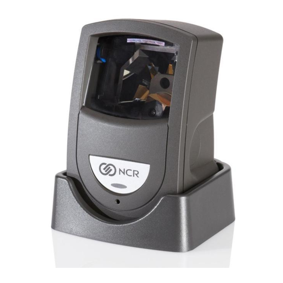
Introduction Chapter 1: The new NCR RealPOS Presentation Scanner (7893) represents the latest technology in laser scanning. It features bi-optic electronics, including dual video, flash download technology, and flash programmability. It is a small, compact unit that weighs about 14 ounces. Being a presentation scanner, it permits you to present the bar code label to the scanner or pass it by for bar code reading. -
Page 19: Chapter 2: Product Information
Product Information Chapter 2: The 7893 is designed to operate within a wide environmental range. Being a small peripheral unit, it does not require any special wiring or mounting. Normally, its requirements are within those of the host terminal or PC. Physical Considerations The 7893 is a lightweight unit with design consideration given to handling by store personnel. -
Page 20: Environmental Considerations
Chapter 2: Product Information Environmental Considerations The 7893 operates in all standard-working environments. Temperature and humidity ranges permitted are greater when the 7893 is in storage or transit. The following table gives the various environmental requirements. Temperature Temperature Change Humidity Range 10°C to 40°C 5% - 95% Operating Environment... -
Page 21: Features And Options
Scanning Performance The NCR 7893 uses laser light to create a pattern of 20 scan lines. As a bar code passes through these scan lines, the 7893 scanner uses the reflected light to identify the location of each bar in the bar code. -
Page 22: Autodiscrimination
Chapter 2: Product Information Autodiscrimination The 7893 can decode a variety of barcodes. The ability to differentiate the various barcode types is a standard feature of the 7893. The following is a list of the different barcode types: UPC–A and UPC–E ... -
Page 23: Usb Peripheral Port And Main (Pos) Communication Port
Chapter 2: Product Information USB Peripheral Port and Main (POS) Communication Port The 7893 includes a USB Peripheral ports and a Main (POS) Communication Port. This port is included to permit an easy connection for peripherals and to improve its capabilities by permitting the devices to be hot–swappable (connecting or disconnecting devices without restarting the unit). -
Page 24: Operator Interface
Chapter 2: Product Information Operator Interface Interface between the operator and the 7893 is very minimal. Messages are sent from the 7893 to the operator through LED status indicator, audio tones, and voice messages. Voice Messages If the 7893 has voice enabled, certain mode changes and error conditions are alerted by synthesized voice messages. -
Page 25: Not-On-File
Power Supply 23756 The Power Supply provides the required DC voltage of the NCR 7893 The Power Cord plugs into an electrical outlet and connects to the Power Supply. A low voltage Power Cable connects the Power Supply to the 7893. Several power cords are available depending on the country of installation. -
Page 26: Parameter Programming
Chapter 2: Product Information Parameter Programming The NCR 7893 may need to be configured to meet specific installation needs. The 7893 uses special programming tags to modify the various programming parameters (refer to Chapter 5). This can be done through the following: ... -
Page 27: Ongoing Wellness Check
Chapter 2: Product Information Ongoing Wellness Check Scan Doctor runs continuously the moment 7893 is turned on. It constantly performs on-going diagnostic tests while the unit is running. These diagnostic tests include the following: Spinner Motor Speed Test. IBM RS-485 TERMPWR Test ... -
Page 28: Service Diagnostics
2-10 Chapter 2: Product Information Error Code Sequence GREEN GREEN GREEN GREEN (PAUSE) (PAUSE) (PAUSE) (PAUSE) (PAUSE) Note: The 7893 will flash sequences of changing colors that match the Scan Advisor (5-LED light bar) color sequences used on other PXA scanners like the 7884. Except that the 7893 must flash the colors in sequence instead of displaying them all at once. -
Page 29: Chapter 3: Installation
If the scanner has been damaged due to shipping, notify the shipping carrier and the NCR representative. If other damages are found, notify NCR or the other supplier if not purchased directly from NCR. Out of Box failures are handled through the NCR customer Satisfaction Hot line. -
Page 30: Verify Correct Cables
Chapter 3: Installation Verify Correct Cables The following table identifies the most common interface cables required for the different host connections that can be made with the 7893. See your NCR representative for additional cables. Cable Number Description 1432-C899-0040 Cable – USB, Latching, 7892SA, black 1432-C679-0040 Cable –... -
Page 31: Determine Scanner Location
Chapter 3: Installation Determine Scanner Location When identifying a location for the 7893 scanner, consider the length of the connecting cables. The electrical outlet used for the Power Module can be approximately 74 in. (188 cm) from the host terminal. Depending on the Scanner Module Cable, the scanner can be approximately 9 ft. (274 cm), 6.6 feet (2 meters) or 13.1 feet (4 meters) from the host terminal or PC. -
Page 32: Installing The 7893
Chapter 3: Installation Installing the 7893 The 7893 can be connected to the host terminal through a PS/2 keyboard connector. Scan data is input into the PS/2 keyboard port. When connected in this configuration the 7893 cannot receive commands from the host terminal. Note: For the 7893 there is only a single transmit message buffer. -
Page 33: Usb Keyboard Wedge Communication
Chapter 3: Installation USB Keyboard Wedge Communication The 7893 can emulate a USB keyboard device by enumerating itself as an HID keyboard. By doing so, it passes barcodes directly to the host’s keyboard driver. This eliminates the need of installing a third party driver since the operating system’s native keyboard input driver will be used. -
Page 34: Connecting Power
Chapter 3: Installation Connecting Power 1. Verify that you have the correct Power Module for your electrical outlet. 2. Connect the power connector to the Interface Cable. Depending on the installation, this may be a connector on the cable or a box on the end of the cable. 3. -
Page 35: Modifying The Scanner Program
IBM-USB format. NCR (RS-232) USB The 7893 can communicate with the host terminal through a USB cable. This parameter enables the NCR (RS-232) format. Note: Two programming tags must be scanned to enable this parameter: Hex E followed by Hex 0. -
Page 37: Chapter 4: Operating The Scanner
Operating the Scanner Chapter 4: Scanner Components Before using the 7893, the user needs to be familiar with some of its components. The figure below shows the scanner and identifies some of the parts and features. Scan Window Status Indicator Scanner Module Cable Speaker 27475... -
Page 38: Pass-By Scanning
Chapter 4: Operating the Scanner Pass-by Scanning This type of scanning is the familiar style used at checkout stands, such as in supermarkets. The item is moved across the front of the scanner window with the barcode label oriented to face the scanner window, as shown. - Page 39 Chapter 4: Operating the Scanner 2. Position the bar code label completely within the red Laser Scan Pattern as indicated below. Normally the bar code should be three to four inches from the scanner. When the label is read the LED Status Indicator turns green. If enabled, a Good Read Tone also sounds.
-
Page 40: Hand Scanning
Chapter 4: Operating the Scanner Hand Scanning Occasionally you have merchandise that cannot be picked-up and presented to the scanner. The package may be too heavy or too awkward to hold while trying to position the bar code label. In these circumstances you can pick up the scanner and take it to the merchandise. The 7893 is designed so that you can easily pick the scanner up and hold it. -
Page 41: Label Rotation
Chapter 4: Operating the Scanner Label Rotation The 7893 can read labels that are presented in many different positions. You can present labels that are rotated left or right 30 degrees from center, up or down 30 degrees from center, and 360 degrees around center. -
Page 42: Distance From Scanner
Chapter 4: Operating the Scanner Distance from Scanner For optimum reading, the distance you must place the label from the 7893 depends on the density and height of the bar code. You can relate this to focusing a camera, where you change the focus setting based on how far away the object is. -
Page 43: Pacesetter
Chapter 4: Operating the Scanner PACESETTER NCR has continually improved its PACESETTER technology used on NCR scanner products. Starting out as PACESETTER, it progressed to PACESETTER Plus, and then to PACESETTER III. Vendors and printers regularly supply products with overprinted, underprinted, or truncated bar codes to the market. -
Page 44: Read Indicators
Chapter 4: Operating the Scanner PACESETTER III The PACESETTER III feature of the 7893 scanner performs many functions that improve the efficiency of the scanner. It determines what is wrong with a bar code and then fixes it. It also keeps track of problems found. -
Page 45: Programming Speech
Chapter 4: Operating the Scanner Programming Speech Speech on the 7893 is enabled or disabled by scanning the following programming sequence. Speech Enable/Disable toggle Programming Mode Hex 3 Hex 2 Hex D Save and Reset Scan the programming tag sequence once to enable speech. -
Page 46: Taking Care Of Your Scanner
4-10 Chapter 4: Operating the Scanner Taking Care of Your Scanner Although your 7893 is rugged, remember to treat it carefully. Keeping the Scan Window clean helps keep the read rate exceptionally high. Follow these simple instructions to keep your scanner clean and well-maintained. -
Page 47: Chapter 5: Programming
Programming Chapter 5: This overview of programming the 7893 is intended to acquaint you with the overall programming procedure. The “Scanner Programming Summary” section at the end of this chapter is most useful after you have performed the programming function. Programming Mode To program the 7893, it must be in the Programming Mode. -
Page 48: Entering Your Program
3. Save your program by scanning the Save and Reset tag. Requirements Programming Worksheets Programming Tags—Appendix B: NCR Scanner Programming Tags or BST0-2121-74 Help Refer to the “Programming Tags Chart” later in this chapter. Refer to the step-by-step procedure described in “Entering Your Program” section of this chapter. -
Page 49: Programming Considerations
However, if you need to make programming changes, the procedure is very simple. First complete a series of programming worksheets then enter the information using special Programming Tags in Appendix A: NCR Scanner Programming Tags or BST0-2121-74. Programming Tags There are 5 unique tags and 16 hexadecimal (Hex) character tags. The following chart identifies each Programming Tag, its function, and the associated indicators. -
Page 50: Using The Programming Worksheets
7893 sets the parameters to these values. The scanner also indicates via beeps the Default setting. Enter the program into your scanner by scanning the proper sequence of programming tags found in the NCR Scanner Programming Tags (BST0-2121-74). Following are the three major steps to programming your scanner. - Page 51 Chapter 5: Programming 1. Enter the Base Programming state by scanning the Programming Mode tag as the first tag after applying power to your 7893 scanner. 2. Select a Programming Worksheet and enter its parameter data by scanning the Hex tags identified in Your Program at the bottom of the Programming Worksheet.
-
Page 52: Programming Description
Programming Description The 7893 can be remotely programmed from its attached host terminal with no local intervention. To achieve this, special host terminal software (NCR RealPOS Scanner Tool Suite) must be purchased from NCR. This section describes programming a scanner with special bar code tags. -
Page 53: Programming Tags
NCR Scanner Programming Tags (BST0-2121-74) available at www.info.ncr.com. (The tags are also included in Appendix A of this document.) A large number of special programming tags are not needed. There are only five (5) unique tags and sixteen (16) hexadecimal (Hex) character tags. -
Page 54: Default
Chapter 5: Programming Function–In a Parameter Programming If this tag is scanned in a Parameter Program sequence, only the parameter sequence which was aborted is not saved. Any prior sequence that successfully ended with the scanner saying "Program Mode" is saved and the 7893 stays in Program Mode. Indication–In a Parameter Program ... -
Page 55: Hex 0-Hex F
Chapter 5: Programming HEX 0–HEX F Function These sixteen (16) tags enter the selections for each of the parameters in the Parameter Programs. They also select the Parameter Program Indication Hex 0—Scanner says “Zero” with no beeps. If voice disabled, scanner produces a short beep, different frequency from Good Read tone. -
Page 56: Speak Bar Codes Currently Enabled
5-10 Chapter 5: Programming Speak Bar Codes Currently Enabled This bar code prompts the scanner to speak a list of the bar code symbologies that the scanner has been programmed to recognize and read. Refer to Appendix B for the actual programming tag. - Page 57 Chapter 5: Programming 5-11 PROGRAM MODE Bar Codes - 2 Parameter Program Code 39 Disable Enable Minimum Characters Allowed Full ASCII Disable Enable Check Digit Present Disable Enable Transmit Check Digit Disable Enable Allow 1- or 2-Character Disable Enable Tags 11722...
-
Page 58: Enter Specific Parameters (Shortcut Method)
5-12 Chapter 5: Programming Program Entry Procedure The following example is a typical program entry procedure. 1. Disconnect scanner from the host terminal. 2. Apply power to the 7893 (or scan the Reset tag). 3. Scan the Program Mode tag. 4. - Page 59 Chapter 5: Programming 5-13 PROGRAM MODE Bar Codes - 2 Parameter Program Code 39 Disable Enable Minimum 2- F Characters Allowed Full ASCII Disable Enable Check Digit Present Disable Enable Transmit Check Digit Disable Enable Allow 1- or 2-Character Disable Enable Tags 11723...
-
Page 60: Parameter Defaults
5-14 Chapter 5: Programming Program Entry Procedure (Shortcut Method) The following example is a typical program entry procedure. 1. Disconnect scanner from the host terminal. 2. Apply power to the 7893 (or scan the Reset tag). 3. Scan the Program Mode tag. 4. - Page 61 Chapter 5: Programming 5-15 Programming Mode Program Parameters Default Setting UPC/EAN Enable Unused Disable Extend UPC–A to EAN–13 Disable Extend UPC–E to UPC–A Disable Bar Codes-1 Periodical Codes Disable Periodical Code Extension No default value Send Data Data As Decoded Set 2 Tag Label Code 39 Disable...
- Page 62 5-16 Chapter 5: Programming Programming Mode Program Parameters Default Setting Interleaved 2 of 5 Disable Bar Code Length Range Specific Value 1 Value 2 Check Digit Present Disable Transmit Check Digit Disable Interleaved 2 of 5 Tone Disable Bar Codes-3 Tone Length 75 Milliseconds Tone Frequency...
- Page 63 Chapter 5: Programming 5-17 Programming Mode Program Parameters Default Setting Codabar Decoding Disable Codabar Length Range Check 4-36 Codabar Specific Length Check 4-36 Codabar Check Digit Disable Codabar Check Digit Transmission Enable Codabar Tone Length 75 ms Codabar Tone Frequency 2232 Hertz Bar Codes-6 Codabar Tone...
- Page 64 5-18 Chapter 5: Programming Programming Mode Program Parameters Default Setting Baud Rate 9600 Parity 1 Stop Bit and 7–bit RS-232 Parameters-1 Stop Bits and Character Length Length RTS High, Wait For Hand Shake Disable—Scanner- Only models BCC Options Enable— Scanner/Scale Models Interface Control None RS-232 Parameters-2...
-
Page 65: Programming Tips
Chapter 5: Programming 5-19 Programming Tips The following are some tips to help when programming the 7893. Turn the host terminal Off or disconnect all interface cables to the 7893 before entering the program. Some host terminals can corrupt the program if they are running and are connected to the 7893 while entering the program. -
Page 66: Program Parameter Descriptions
The 7893 can communicate to the host terminal through a USB cable. This parameter enables the scanner to use IBM’s proprietary version of HID–type USB protocol. NCR (RS-232 USB) The 7893 can communicate with the host terminal through a USB cable. This parameter enables the NCR (RS-232) format. -
Page 67: Good Read Tone
Chapter 5: Programming 5-21 Note: Two programming tags must be scanned to enable this parameter: Hex E followed by Hex 0. RS-232 RS-232 is used to connect the 7893 to almost any RS-232 type of communications device. This protocol uses 7-bit ASCII by default to send tag data to the device. Good Read Tone Your Program Good Read Tone... -
Page 68: Tone Frequency (Hertz)
The Not-On-File tone goes off when the scanner receives a command from the host terminal to do so. In RS-232 protocol, there is a Not–On–File command. Refer to the NCR Scanner/Scale Interface Programmer's Guide (BD20-1074-A) for more information about the Not-On-File... -
Page 69: Timers
Disable Enable Restart Limit has no effect. NOTE: NCR suggests that you do not set the Active Time parameter to 0. Leaving the laser light on all the time reduces its life expectancy. 27550 The Timers programming mode controls the two 7893 timers: Lockout Time and Active Time. -
Page 70: Restart Lockout Timer
Hex 0 through Hex 3 tags, respectively. Note: NCR suggests that the Active Time parameter not be set to 0. When set to 0, the laser lights will be ON all the time which reduces the life expectancy of the laser diodes. -
Page 71: Bar Codes-1
Chapter 5: Programming 5-25 Bar Codes–1 Your Program Bar Codes - 1 UPC/EAN Unused Extend Extend Periodical Periodical Send Set 2 Tag UPC-A UPC-E Codes Code Data Label Extension UPC/EAN Disable Enable B Unused Disable C Extend UPC-A To EAN-13 Disable Enable D Extend UPC-E... -
Page 72: Extend Upc-A To Ean-13
5-26 Chapter 5: Programming If reading UPC/EAN bar codes is disabled, there are no other entries allowed for this parameter. However, if reading UPC/EAN bar codes is enabled, the remaining parameters can be programmed. Extend UPC–A to EAN–13 The Extend UPC–A to EAN–13 parameter determines whether to pad the tag data, changing 12-digit UPC tags to 13-Character EAN tags. -
Page 73: Bar Codes-2
Chapter 5: Programming 5-27 Bar Codes–2 Your Program Bar Codes - 2 Code 39 Minimum Full Check Digit Transmit Allow 1- Characters ASCII Present Check Digit Allowed 2-Character Tags Code 39 Disable Enable Minimum 2 - F Default Characters Allowed Full ASCII Disable Enable... -
Page 74: Code 39 Tone
5-28 Chapter 5: Programming Minimum Characters The Minimum Characters Allowed parameter defines how many characters in a bar code must be read the same by two separate scans before determining a valid read has occurred. This option should be set to the number of characters in a typical tag which ensures that the scanner reads typical tags with at least two complete good scans before sending the tag data to the host terminal. -
Page 75: Tone Frequency
Chapter 5: Programming 5-29 Tone Frequency This parameter permits you to set the frequency of the Code 39 tone. Set this parameter by scanning the appropriate Hex tag (Hex 0 to Hex 7). Hex Tag Frequency in Hertz Hex 0 3348 Hz Hex 1 2976 Hz... -
Page 76: Scans Required
5-30 Chapter 5: Programming Scans Required This parameter sets the number of scans required to read a Code 39 bar code. Increasing the number of scans can improve reading nominal bar codes. There are four settings: 1 scan, 2 scans, 3 scans, and 4 scans. The default is 1 scan. Set this parameter by scanning the appropriate Hex tag (Hex 1 to Hex 4). -
Page 77: Bar Codes-3
Chapter 5: Programming 5-31 Bar Codes–3 Your Program Interleaved Bar Code Value 1 Value 2 Check Digit Transmit Bar Codes - 3 2 of 5 Length Present Check Digit Interleaved 2 of 5 Disable Enable Bar Code Length Range Specific Check Check Character... -
Page 78: Bar Code Length
5-32 Chapter 5: Programming Bar Code Length The Bar Code Length parameter selects the method for determining if an Interleaved 2 of 5 bar code is a valid length. The Range Check method identifies a length range by specifying the minimum and maximum number of characters. -
Page 79: Tone Length
Chapter 5: Programming 5-33 Tone Length The Tone Length parameter permits you to set the length of the Interleaved 2 of 5 tone. Set this parameter by scanning the appropriate Hex tag (Hex 0 to Hex F). Each Hex tag is incremented by 15 milliseconds. -
Page 80: Scans Required
5-34 Chapter 5: Programming Scans Required This parameter sets the number of scans required to read an Interleaved 2 of 5 bar code. Increasing the number of scans can improve reading nominal bar codes. There are four settings: 1 scan, 2 scans, 3 scans, and 4 scans. The default is 2 scans. Set this parameter by scanning the appropriate Hex tag (Hex 1 to Hex 4). -
Page 81: Code 128
Chapter 5: Programming 5-35 The Bar Codes 4 programming mode contains programming parameters for Code 128 bar codes. Refer to the “Parameter Defaults“section earlier in this chapter for the factory defined default value of each programming parameter. Code 128 The Code 128 parameter contains two selections: Disable and Enable. Disable reading Code 128 bar codes by scanning the Hex 0 tag and enable reading by scanning the Hex 1 tag. -
Page 82: Scans Required
5-36 Chapter 5: Programming Scans Required This parameter sets the number of scans required to read a Code 128 bar code. Increasing the number of scans can improve reading nominal bar codes. There are four settings: 1 scan, 2 scans, 3 scans, and 4 scans. The default is 1 scan. Set this parameter by scanning the appropriate Hex tag (Hex 1 to Hex 4). -
Page 83: Scans Required On Gs1 Databar-14
Chapter 5: Programming 5-37 GS1 DataBar Enable This parameter contains 4 selections. Disable reading GS1 DataBar bar codes by scanning the Hex 0 programming tag. Reading either or both GS1 DataBar–14 and GS1 DataBar–E bar codes is enabled with this parameter. -
Page 84: Gs1 Databar Expanded Application Identifier Programming Options
5-38 Chapter 5: Programming GS1 DataBar Expanded Application Identifier Programming Options There are situations where it may be desirable to disable certain DataBar Expanded Application Identifiers (AI) while enabling others. This may be due to the system software not being capable of handling certain DataBar Expanded tag data. Following are examples of such scenarios and how the scanner can be programmed to enable or disable the scanning of specific DataBar AIs: 1. - Page 85 Chapter 5: Programming 5-39 Enables all DataBar Expanded Enable General DataBar Expanded except AIs specifically disabled Program Mode, Hex 7, Hex 1, Hex E, Save and Reset (default) Disable General DataBar Expanded Disables all DataBar Expanded except AIs specifically enabled Program Modes, Hex 7, Hex 1, Hex F, Save and Reset Specifically Enable DataBar AI 8110 Set DataBar Expanded AI 8110...
-
Page 86: Bar Codes-6
5-40 Chapter 5: Programming Bar Codes–6 Your Program Bar Codes - 6 Codabar Codabar Codabar Codabar Decoding Legth Check Digit Check Digit Transmission Codabar Decoding Disable Enable Codabar Codabar Length Range Check Length 1-36 1-36 Minimum Length Maximum Length (Default = 4) (Default = 36) Codabar Specific Length Check 1-36... -
Page 87: Codabar Tone Length
Chapter 5: Programming 5-41 Codabar Tone Length The Codabar Tone Length parameter permits you to set the length of the Codabar tone. Set this parameter by scanning the appropriate Hex tag (Hex 0 to Hex F). Each Hex tag is incremented by 15 milliseconds. -
Page 88: Bar Codes-7
5-42 Chapter 5: Programming Bar Codes–7 Your Program Bar Codes - 7 Pharmacode Disable Enable Pharmacode Check Digit Disable Enable Transmission 25516 The Bar Codes 7 programming mode contains programming parameters for Pharmacode bar codes. Refer to the “Parameter Defaults” section earlier in this chapter for the factory defined default value of each programming parameter. -
Page 89: Label Identifiers
25514 The Label Identifiers programming mode selects the parameters for adding label identifiers to communication messages. These identifiers apply to the NCR USB and RS-232 communication protocols. Label identifiers for the other modes of communication are determined by the firmware and are not programmable. -
Page 90: Common Byte 1 And Common Byte 2
5-44 Chapter 5: Programming Default Prefix Scan the Hex 0 tag to use the default prefix. The default label identifiers vary depending on the type of bar code read. Following are the default identifiers for each bar code type: Bar Code Type ASCII UPC-A UPC-E... -
Page 91: Bar Code Type
Chapter 5: Programming 5-45 Bar Code Type The Bar Code Type parameter selects the bar code type for entering its associated label identifier information. After entering a Bar Code Type, enter the Common Byte and Unique Identifier. This procedure repeats until the label identifiers are specified for each bar code type. Scan the Hex 0 through Hex 9 tag to enter the appropriate Bar Code Type. -
Page 92: Parameters 1
5-46 Chapter 5: Programming RS-232 Parameters 1 Your Program RS-232 Baud Parity Stop Bits Handshake Parameters - 1 Rate Character Length Baud Rate 1200 2400 4800 9600 19200 Parity Even None Stop Bits 1 Stop Bit 1 Stop Bit 2 Stop Bits 2 Stop Bits Character 7-Bit Character... -
Page 93: Stop Bits And Character Length
Chapter 5: Programming 5-47 Stop Bits and Character Length The Stop Bits and Character Length parameter contains four selections: 1 Stop Bit and 7-bit Character Length, 1 Stop Bit and 8-bit Character Length, 2 Stop Bits and 7-bit Character Length, and 2 Stop Bits and 8-bit Character Length. Choosing no parity and 7-bit Character Length causes the 7893 to send two (2) stop bits;... -
Page 94: Parameters 2
5-48 Chapter 5: Programming RS-232 Parameters 2 Your Program RS-232 BCC Options Interface Control Check Digit Parameters - 2 BCC Options Disable Enable Interface Control None ACK/NAK XOn/XOff ACK/NAK & XOn/XOff Check Digit Disable UPC-A Enable UPC-A Disable UPC-A Enable UPC-A Disable EAN-8 Enable EAN-8 Disable EAN-8... -
Page 95: Check Digit
Chapter 5: Programming 5-49 Interface Control The Interface Control parameter permits control of the transfer of data between the scanner and the host terminal. The options are None, enable ACK/NAK, enable XOn/XOff, and enable both ACK/NAK and XOn/XOff. If enable ACK/NAK is selected, each message sent to the host terminal must be acknowledged before sending the next message. -
Page 96: Rs-232 Terminator Byte
5-50 Chapter 5: Programming Prefix Byte The Prefix Byte parameter contains two selections: Disable and Enable. Scan the Hex 0 tag to disable the Prefix Byte, or the Hex 1 tag to enable it. ASCII Code The ASCII Code parameter permits the specification of what ASCII code to use for the Prefix Byte. -
Page 97: Rs-232 Communications Options
Chapter 5: Programming 5-51 Terminator Byte There are two RS-232 Terminator Bytes available–the second Terminator Byte being a direct entry only. Therefore after programming the First Terminator Byte Hex 2, Hex 3 and Hex C must be scanned to be able to program the Second Terminator Byte. ASCII Code The ASCII Code parameter for RS-232 Terminator Byte and Prefix Byte has the same function. -
Page 98: Scanner/Scale Format
The difference between the scanner only and the scanner/scale format is that the scanner/scale format has an address and a function code following the optional Prefix Byte. For more detailed information on message formats refer to the NCR Scanner/Scale Interface Programmer's Guide (BD20-1074-A). -
Page 99: Miscellaneous Parameters
Chapter 5: Programming 5-53 Miscellaneous Parameters Your Program Miscellaneous Host Tone IBM Retransmit Speech IBM-485 / IBM-USB Parameters Control Control Tag Data Format Host Tone Control Disable Enable IBM Retransmit Control 3 Times Forever Speech Toggle Between Enable and Disable Speech IBM-485 / IBM-USB Tag Data Format ASCII... -
Page 100: Number System Character Parameter
ASCII characters. Therefore, when selecting Communications Protocol choice 4 or B, NCR recommends that the tag format be set to ASCII. For handheld bar code readers, refer to the “Communications Protocol” section earlier in this chapter. -
Page 101: Programming Worksheets
Chapter 5: Programming 5-55 Hex 1—UPC–A and UPC–E Number System Character Sent Hex 4—UPC–E Number System Character Not Sent Hex 5—UPC–E Number System Character Sent Hex 6—UPC–A Number System Character Not Sent Hex 7—UPC–A Number System Character Sent Programming Worksheets The programming worksheets provide a convenient method of defining the 7893 program before loading it into the unit. -
Page 102: Good Read Tone
5-56 Chapter 5: Programming Good Read Tone Your Program Good Read Tone Protocol Tone On/Off Tone When entering Tone Frequency, the adjustment can be incremented upward by scanning the Hex B tag. Each time Frequency you scan the Hex B , the tone frequency increases one unit. (Hertz) Scan the End tag or a valid Hex tag to end this mode. -
Page 103: Timers
900 ms Lockout Timer Restart Limit [F] Disable Enable Restart Limit has no effect. NOTE: NCR suggests that you do not set the Active Time parameter to 0. Leaving the laser light on all the time reduces its life expectancy. 27550... -
Page 104: Bar Codes-1
5-58 Chapter 5: Programming Bar Codes–1 Your Program Bar Codes - 1 UPC/EAN Unused Extend Extend Periodical Periodical Send Set 2 Tag UPC-A UPC-E Codes Code Data Label Extension UPC/EAN Disable Enable B Unused Disable C Extend UPC-A To EAN-13 Disable Enable D Extend UPC-E... -
Page 105: Bar Codes-2
Chapter 5: Programming 5-59 Bar Codes–2 Your Program Bar Codes - 2 Code 39 Minimum Full Check Digit Transmit Allow 1- Characters ASCII Present Check Digit Allowed 2-Character Tags Code 39 Disable Enable Minimum 2 - F Default Characters Allowed Full ASCII Disable Enable... -
Page 106: Bar Codes-3
5-60 Chapter 5: Programming Bar Codes–3 Your Program Interleaved Bar Code Value 1 Value 2 Check Digit Transmit Bar Codes - 3 2 of 5 Length Present Check Digit Interleaved 2 of 5 Disable Enable Bar Code Length Range Specific Check Check Character... -
Page 107: Bar Codes-4
Chapter 5: Programming 5-61 Bar Codes–4 Your Program Bar Codes - 4 Code 128 Minimum UCC 128 Data Characters Allowed Bar Codes - 4 Partial Decoding Code 128 Disable Enable Minimum Data Characters Allowed EAN/UCC 128 Disable Enable NOTE: Direct Entry Only. Partial Decoding Disable... -
Page 108: Bar Codes-5
5-62 Chapter 5: Programming Bar Codes–5 Your Program Bar Codes - 5 GS1 DataBar Scans Required Scans Required UCC-128 Enable On GS1 DataBar 14 On GS1 DataBar E Emulation Mode GS1 DataBar Enable Disable Enable Enable Enable GS1 DataBar 14 GS1 DataBar E GS1 DataBar 14 Only... -
Page 109: Bar Codes-6
Chapter 5: Programming 5-63 Bar Codes–6 Your Program Bar Codes - 6 Codabar Codabar Codabar Codabar Decoding Legth Check Digit Check Digit Transmission Codabar Decoding Disable Enable Codabar Codabar Length Range Check Length 1-36 1-36 Minimum Length Maximum Length (Default = 4) (Default = 36) Codabar Specific Length Check 1-36... -
Page 110: Label Identifiers
5-64 Chapter 5: Programming Label Identifiers Your Program Label Identifier Common Common Bar Code Common Unique Identifier Identifiers Type Byte 1 Byte 2 Type Byte Identifier Type Default Prefix None Unique Prefix Common Byte 1 0 - 7 0 - F Default Hex Character Hex Character... -
Page 111: Number System Character
Chapter 5: Programming 5-65 Number System Character Your Program Number System UPC-A & UPC-E UPC-A UPC-E Character Number System Number Number System System UPC-A & UPC-E Number System Not Sent Sent UPC-E Number System Not Sent Sent UPC-A Number System Not Sent Sent 24040... -
Page 112: Parameters 2
5-66 Chapter 5: Programming RS-232 Parameters 2 Your Program RS-232 BCC Options Interface Control Check Digit Parameters - 2 BCC Options Disable Enable Interface Control None ACK/NAK XOn/XOff ACK/NAK & XOn/XOff Check Digit Disable UPC-A Enable UPC-A Disable UPC-A Enable UPC-A Disable EAN-8 Enable EAN-8 Disable EAN-8... -
Page 113: Rs-232 Prefix Byte
Chapter 5: Programming 5-67 RS-232 Prefix Byte Your Program RS-232 Prefix Byte ASCII Code Prefix Byte Prefix Byte Disable Enable ASCII Code 0 - 7 0 - F Default Hex Character Hex Character (ASCII Code Chart) (ASCII Code Chart) 22774 RS-232 Terminator Byte Your Program RS-232... -
Page 114: Rs-232 Communications Options
5-68 Chapter 5: Programming RS-232 Communications Options Your Program RS-232 Communication Scanner or Good Options Delay Scanner / Weigh Scale Format Tone RS-232 Delay 1 0 1 0 1 0 1 0 1 2 No Delay 10 Milliseconds 50 Milliseconds Scanner or Scanner / Scanner Only... -
Page 115: Code 128 Tone Length
Chapter 5: Programming 5-69 Code 128 Tone Length Selection Programming Tag Sequence 0 ms Programming Mode, Hex 7, Hex 0, Hex 0, Hex 0, Save and Reset 15 ms Programming Mode, Hex 7, Hex 0, Hex 0, Hex 1, Save and Reset 30 ms Programming Mode, Hex 7, Hex 0, Hex 0, Hex 2, Save and Reset 45 ms... -
Page 116: Code 128 Minimum And Maximum Tag Length
5-70 Chapter 5: Programming Code 128 Minimum and Maximum Tag Length Selection Programming Tag Sequence Length Programming Mode, Hex 7, Hex 2, a, v, w, x, y, Save and Reset where a = Ø (Range of lengths) or 1 (Specific Length) v = 1-3 (default is 3) w = 1-9 (default is 9) x = 1-3 (default is 3) -
Page 117: Code 39 Tone Frequency
Chapter 5: Programming 5-71 Code 39 Tone Frequency Setting Programming Tag Sequence Selection 3348 Hz Programming Mode, Hex 7, Hex 0, Hex 4, Hex 0, Save and Reset Programming Mode, Hex 7, Hex 0, Hex 4, Hex 1, Save and Reset 2976 Hz 2679 Hz Programming Mode, Hex 7, Hex 0, Hex 4, Hex 2, Save and Reset... -
Page 118: Code 39 Stitch
5-72 Chapter 5: Programming Code 39 Stitch Selection Programming Tag Sequence Disable Programming Mode, Hex 7, Hex 0, Hex 9, Hex 2, Save and Reset Enable Programming Mode, Hex 7, Hex 0, Hex 9, Hex 3, Save and Reset 24452 Code 39 CD Length1 24454 Code 39 CD Length2... -
Page 119: Interleaved 2 Of 5 Tone Length
Chapter 5: Programming 5-73 Interleaved 2 of 5 Tone Length Selection Programming Tag Sequence 0 ms Programming Mode, Hex 7, Hex 0, Hex 6, Hex 0, Save and Reset 15 ms Programming Mode, Hex 7, Hex 0, Hex 6, Hex 1, Save and Reset 30 ms Programming Mode, Hex 7, Hex 0, Hex 6, Hex 2, Save and Reset 45 ms... -
Page 120: Interleaved 2 Of 5 Cd Length1
4 scans Programming Mode, Hex 6, Hex B, Hex 5, Hex 4, Save and Reset Note: This is an Advanced Programming Feature and should only be done under the recommendation and direction of NCR; otherwise, unexpected results may occur. 25645... -
Page 121: Interleaved 2 Of 5 Overlap
Programming Mode, Hex 6, Hex B, Hex E, Hex 9, Save and Reset Note: This is an Advanced Programming Feature and should only be done under the recommendation and direction of NCR; otherwise, unexpected results may occur. 25647 Enable/Disable Interleaved 2 of 5 Partials... -
Page 122: Gs1 Databar Tone Length
5-76 Chapter 5: Programming GS1 DataBar Tone Length Setting Selection Programming Tag Sequence 0 ms Programming Mode, Hex 7, Hex 4, Hex 0, Hex 0, Save and Reset 15 ms Programming Mode, Hex 7, Hex 4, Hex 0, Hex 1, Save and Reset 30 ms Programming Mode, Hex 7, Hex 4, Hex 0, Hex 2, Save and Reset 45 ms... -
Page 123: Gs1 Databar-E Ai 93 To Code 39 Tag Data Conversion
Chapter 5: Programming 5-77 GS1 DataBar–E AI 93 to Code 39 Tag Data Conversion Setting Selection Programming Tag Sequence Disable Programming Mode, Hex 7, Hex 0, Hex A, Hex 2, Save and Reset Default Enable Programming Mode, Hex 7, Hex 0, Hex A, Hex 3, Save and Reset 24955 GS1 DataBar–E AI 94 to UCC–128 Tag Data Conversion Selection... -
Page 124: Codabar Tone Length
5-78 Chapter 5: Programming Codabar Tone Length Selection Programming Tag Sequence Setting 0 ms Programming Mode, Hex 7, Hex 4, Hex 3, Hex 0, Save and Reset 15 ms Save and Reset Programming Mode, Hex 7, Hex 4, Hex 3, Hex 1, 30 ms Programming Mode, Hex 7, Hex 4, Hex 3, Hex 2, Save and Reset... -
Page 125: Codabar Halves
Chapter 5: Programming 5-79 Codabar Halves Selection Programming Tag Sequence Setting Disable Programming Mode, Hex 7, Hex 4, Hex 5, Hex 2, Save and Reset Default Enable Programming Mode, Hex 7, Hex 4, Hex 5, Hex 3, Save and Reset 25325 Codabar Stitch Selection... -
Page 126: Codabar Hard Correlation
5-80 Chapter 5: Programming Codabar Hard Correlation Selection Programming Tag Sequence Setting Disable Programming Mode, Hex 6, Hex B, Hex 2, Hex 6, Save and Reset Default Enable Programming Mode, Hex 6, Hex B, Hex 2, Hex 7, Save and Reset 25323 Number of Codabar Overlaps Required Selection... -
Page 127: Number Of Upc/Ean Scans Required
Chapter 5: Programming 5-81 Number of UPC/EAN Scans Required Selection Programming Tag Sequence 1 scan Programming Mode, Hex 6, Hex B, Hex 3, Hex 1, Save and Reset 2 scans Programming Mode, Hex 6, Hex B, Hex 3, Hex 2, Save and Reset 3 scans Programming Mode, Hex 6, Hex B, Hex 3, Hex 3, Save and Reset 4 scans... -
Page 128: Number Of Minimum Code 39 Characters In Code 39 Partial
5-82 Chapter 5: Programming Number of Minimum Code 39 Characters in Code 39 Partial Selection Programming Tag Sequence 2 characters Programming Mode, Hex 6, Hex B, Hex C, Hex 2, Save and Reset 3 characters Programming Mode, Hex 6, Hex B, Hex C, Hex 3, Save and Reset 4 characters Programming Mode, Hex 6, Hex B, Hex C, Hex 4, Save and Reset 5 characters... -
Page 129: Command-Type Disable
Chapter 5: Programming 5-83 Command–type Disable Selection Programming Tag Sequence Setting Disable Programming Mode, Hex 6, Hex 7, Hex 8, Save and Reset Default Enable Programming Mode, Hex 6, Hex 7, Hex 9, Save and Reset 24959 Ignore RS-232 Commands from Host Terminal Selection Programming Tag Sequence Setting... -
Page 130: Ean-13 99 Coupons
5-84 Chapter 5: Programming EAN–13 99 coupons Selection Programming Tag Sequence Setting Enable Programming Mode, Hex 7, Hex 1, Hex A, Save and Reset Default Disable Programming Mode, Hex 7, Hex 1, Hex B, Save and Reset 24968 Expand E to EAN–13 Directly 25336 Scanner Power-On State Selection... -
Page 131: Usb Programming
1. Programming Mode tag—puts scanner in base programming state. 2. Hex 1, Hex 0, Hex E, Hex 0—sets the scanner to NCR USB communications protocol. 3. Save and Reset—saves the program just entered and resets the 7893. -
Page 133: Chapter 6: Special Programming
Special Programming Chapter 6: Some of the 7893 features require programming that is somewhat different than the normal programming. Changing Program Defaults to Current Parameters Set Current Parameters to Default Values The 7893 comes from the factory with specific default values already determined for the various programming parameters. -
Page 134: Convert Upc-E Tags To Ean-13 Tags
Chapter 6: Special Programming Convert UPC–E Tags to EAN–13 Tags UPC–E tags can be converted directly to EAN–13 tags. This function is only needed if UPC–A tags are not to be converted to EAN–13 tags. The default is to disable this function. ... -
Page 135: Enable/Disable Code 128 Partials
Chapter 6: Special Programming Enable/Disable Code 128 Partials When decoding Code 128 using partial scans, sometimes a Decode error is generated. However, several conditions must occur to cause the misread. If having problems reading Code 128 bar codes, try disabling partials. ... -
Page 136: Transmitting Label Data
Chapter 6: Special Programming Transmitting Label Data Transmission of a multi-symbol label consists of a separate message for each of the symbols. The symbol with the lower numbered flag digits is transmitted first. For example, for the 3- symbol combination of JAN-13 flag 21, JAN-13 flag 29, and JAN-13 flag 96, the symbol with flag digits 21 is transmitted first, the symbol with flag digits 29 is transmitted second, and the symbol with flag digits 96 is transmitted third. -
Page 137: Scanning Upc/Ean/Jan Tags Without A Center Band
Chapter 6: Special Programming Scanning UPC/EAN/JAN Tags without a Center Band Some applications require reading UPC/EAN/JAN bar codes without a center band. This function can be enabled or disabled. The default is to disable reading tags without a center band. ... -
Page 138: Gs1 Databar
Chapter 6: Special Programming GS1 DataBar GS1 DataBar, formerly Reduced Space Symbology (RSS), permits more data to be recorded in a smaller physical space. This is accomplished by encoding the data in large symbol characters rather than encoding each data character separately. Also, no quiet zone is required around the symbols. -
Page 139: Gs1 Databar Expanded Stacked
Chapter 6: Special Programming GS1 DataBar Expanded Stacked GS1 DataBar Expanded Stacked is similar too GS1 DataBar-14 Stacked except it uses the GS1 DataBar Expanded format for creating the symbol. 0192 1234 5698 7457 3202 0000 9939 0200 296 19257 Send GS1 DataBar14 as EAN13 Tag Data When enabled, the scanner sends the last 13 digits of the GS1 DataBar14 data to the host terminal. -
Page 140: Terminal Coupon Select 2 Parameters
Chapter 6: Special Programming 5. Repeat steps 1 through 4 to set the second Coupon Select 1 parameter. Suggested Programming Sequence Programming Mode Hex 3 and Hex 8 Hex 1 Save and Reset Programming Mode ... -
Page 141: Voice Volume
RS-232 Obtaining the Tools and New Firmware If you will be reflashing a number of scanners of varying ages, you should install the NCR RealPOS Scanner Flash tool for Windows. All tools and firmware for the 7893 are available on... -
Page 142: Acquiring And Installing The Realpos Scanner Flash Tool For Windows
6-10 Chapter 6: Special Programming Acquiring and Installing the RealPOS Scanner Flash Tool for Windows 1. Go to NCR website (www.ncr.com), and click on Support in the topics banner at the top of the page. Select Drivers and PatchesRetail Support Files (Drivers, Firmware, Operating Systems, Platform Software, BIOS, etc.)... -
Page 143: Acquiring Firmware
The following is an example. Download the desired firmware version into the C:\Program Files\NCR\RealScan\NCRRSFlash directory and extract the file to the same directory. Note: The file extracted will be the actual firmware file with a .bin extension. This is the file that is flashed into the scanner. -
Page 144: Firmware Flashing Procedure
4. Connect the above-mentioned RS-232 Cable in the interface connector of the 7893 and to the COM port of the host terminal. 5. Apply power to the 7893. 6. Run Flash Tool by double-clicking on the NCR Flash Tool icon on the desktop. - Page 145 Chapter 6: Special Programming 6-13 7. Port settings must be configured first before flashing firmware to the scanner. Select Port Settings in the main window and select the Modify INI button. 8. Select one of the radio buttons under the Communications Protocol Group within the Port Settings tab. For RS‐232 communication protocol, you can configure more settings under the RS‐232 Settings group. Right‐click on one of the cells in the table to either change the parameter value or restore it to its default value. ...
- Page 146 6-14 Chapter 6: Special Programming 9. Select Save after making changes to the settings. 10. Select Use Defaults if default settings are preferred. A message box will display informing that all settings will be set to default. Select Yes to confirm. 11. After configuring the necessary port settings, choose the scanner you want to flash the firmware to. 12. Select Modify INI after a scanner model has been chosen. Select the Update Firmware checkbox and choose the firmware BIN file you want to flash to the scanner. For your preference you may enable Flash Override and Section Override by selecting their checkboxes. Select Save to save and apply these settings. 13. Select Run Flash from the main toolbar to start flashing the firmware to the scanner. ...
-
Page 147: Flash Utility Notes
14. The application will initialize communication with the scanner in the port you have specified in the settings. When initialization is successful, the following window will display and show the progress of the flashing process. 15. Exit the NCR Flash Tool application and disconnect the scanner from the host terminal once firmware flashing is finished. Flash Utility Notes If you are unsure exactly what firmware is in your scanner, or are unsure which of the Scanner Tool Suite to use, use this procedure to determine the firmware version inside your scanner. - Page 148 6-16 Chapter 6: Special Programming 3. Scan the HEX 4 Tag. Hex 4 24986 4. Scan the HEX A Tag. Hex A 24987 The scanner will speak the firmware level. It will say: “PXA scanner 4 9 7 …”. Make sure to write down the numbers being spoken after “4 9 7”. This will be used to determine the next step.
-
Page 149: Ncr Realpos Scanner Flash Drive Support
The scanner flash drive support files includes an INI file (created by the NCR RealPOS Scanner Flash Drive Prep Tool) that informs the scanner what tasks are to be performed, a firmware flash file for upgrading a scanner to a particular version, and a configuration file to configure a scanner for a particular end-user. -
Page 150: Ncr Realpos Scanner Flash Drive Prep Tool
NCR RealPOS Scanner Flash Drive Prep Tool In order to minimize the need for a PC at the scanner site, The NCR RealPOS Scanner Flash Drive Prep Tool preps a flash drive so that the scanner could understand its contents and performs the tasks defined inside the device prepared by the host terminal software. - Page 151 7884: 497-0460386 7878: 497-0461765 7874: 497-0459952 7893: any For more information on how to use the NCR RealPOS Scanner Flash Drive Prep Tool, please refer to the NCR RealPOS Scanner Tool Suite Guide (B005-0000-1883) documentation.
-
Page 153: Chapter 7: Troubleshooting
Troubleshooting Chapter 7: Scanner Operation Summary This summary identifies the correct barcode scanning procedure. Refer to this summary if there is a problem reading a barcode. Scan the Bar Code Label Pass-by Scanning Slide the merchandise across the window of the scanner with the barcode facing the scanner window. -
Page 154: Tones And Status Indicators
Chapter 7: Troubleshooting Tones and Status Indicators Your 7893 uses tones and LED Status Indicator light to identify problems. It performs diagnostics that check various scanner functions at different times. Diagnostic checks are made each time power is applied to the scanner and while the scanner is operating. If your 7893 does not work properly, you might be able to determine the problem and correct it without having to send the scanner in for repair. -
Page 155: Scanner Replacement
If the scanner has been damaged due to shipping, notify the shipping carrier and the NCR representative. If other damages are found, notify NCR or the other supplier if not purchased directly from NCR. Out of Box failures are handled through the NCR customer Satisfaction Hot line. -
Page 157: Appendix A: Ps/2 Keyboard Wedge
PS/2 Keyboard Wedge Appendix A: Operational Overview A PS/2 Keyboard Wedge functions by interposing itself on the PS/2 conforming keyboard clock and keyboard data lines that would typically connect just the keyboard to the host terminal. The wedge has the ability to monitor the PS/2 keyboard clock and data lines without affecting standard operations between PS/2 keyboard and host terminal. -
Page 158: Ps/2 Keyboard Emulation
Appendix A: PS/2 Keyboard Wedge PS/2 Keyboard Emulation The wedge uses the existing PS/2 keyboard interface to send data to the host terminal. The standard PS/2 keyboard - host terminal interaction is bidirectional, meaning that the host terminal can send commands and data to the PS/2 keyboard and the PS/2 keyboard can send data to the host terminal. -
Page 159: Programmables
Appendix A: PS/2 Keyboard Wedge Programmables 1. Enable Wedge Communications Interface Programming Mode + 1 + 0 + E + 2 2. Country Code Option United States: Programming Mode + 2 + 8 + A + 0 International: Programming Mode + 2 + 8 + A + 1 3. -
Page 160: Tag Translation Scan Code Table
Appendix A: PS/2 Keyboard Wedge Tag Translation Scan Code Table ASCII ASCII US PS/2 Keyboard Scan Num Lock System Scan Shifted Codes International Scan Codes Option On Characters Characters Codes Space Applicable Eliminate ‘ and “ “ Eliminate < < Eliminate –... -
Page 161: Start/Stop Sentinel Table
Appendix A: PS/2 Keyboard Wedge ASCII ASCII US PS/2 Keyboard Scan Num Lock Shifted System Scan Codes International Scan Codes Option On Characters Characters Codes Start/Stop Sentinel Table The table below can be used to construct the start and stop sentinels. In most cases, the make and break codes will be used to represent a PS/2 keyboard keystroke. - Page 162 Appendix A: PS/2 Keyboard Wedge Make Make Break Make Break Code Break Code Code Code Code Code F0, 16 F0, 2C Insert E0, 70 E0, F0, F0, 1E F0, 3C Home E0, 6C E0, F0, F0, 26 F0, 2A Page Up E0, 7D E0, F0, F0, 25 F0, 1D...
-
Page 163: Tag Message Format
Tag Identifier – 1 byte Tag Data – Variable, depending on the scanned tag Stop Sentinel – 0 to 9 bytes Installation Details The scanner can be connected to a PC with or without using a PS/2 keyboard, using a NCR cable. -
Page 165: Appendix B: Ncr Scanner Programming Tags
NCR Scanner Programming Tags Appendix B: Scanner Programming Tags BST0-2121-74 Release O 27064... - Page 166 Appendix B: NCR Scanner Programming Tags Volume Adjustment 11817 Reset 11818...
- Page 167 Appendix B: NCR Scanner Programming Tags Default R0046 Programming Mode R0042 R0043...
- Page 168 Appendix B: NCR Scanner Programming Tags Save and Reset R0044 Abort R0045 Diagnostic Mode R0041...
- Page 169 Appendix B: NCR Scanner Programming Tags Speak Scanner Serial Number Available with firmware version 497-0433606 or later. 22786 Speak Barcodes Currently Enabled Available with firmware version 497-0433606 or later. 22785 Mode 1 Slot Scanner (PACESETTER Plus) 11500...
- Page 170 Appendix B: NCR Scanner Programming Tags Mode 2 Slot Scanner (PACESETTER Plus) 11501 Reset Tallies Slot Scanner (PACESETTER Plus) 11502 Firmware Flashing Super ASIC and PXA Models 27581...
- Page 171 Appendix B: NCR Scanner Programming Tags Hex 0 R0048 Hex 1 R0049...
- Page 172 Appendix B: NCR Scanner Programming Tags Hex 2 R0050 Hex 3 R0051 Hex 4 R0052...
- Page 173 Appendix B: NCR Scanner Programming Tags Hex 5 R0053 Hex 6 R0054 Hex 7 R0055...
- Page 174 B-10 Appendix B: NCR Scanner Programming Tags Hex 8 R0056 Hex 9 R0057 Hex A R0058...
- Page 175 Appendix B: NCR Scanner Programming Tags B-11 Hex B R0059 Hex C R0060 Hex D R0061...
- Page 176 B-12 Appendix B: NCR Scanner Programming Tags Hex E R0062 Hex F R0063 ASCII Code Chart NULL " & < > R0040...
-
Page 177: Appendix C: Service Diagnostics
IBM host terminal and scanner once the correct communication type has been set in the scanner. If possible, program the scanner first using a power brick supplied by NCR. The following table identifies the Service Diagnostic tests. - Page 178 Appendix C: Service Diagnostics 1. Scan the Diagnostic Mode tag to enter the Base Diagnostic state—this must be the first tag scanned after applying power to the 7893. 2. Scan the Hex 4 tag, then the Hex A tag to read the firmware version level. 3.
-
Page 179: Appendix D: Checkpoint
Checkpoint Appendix D: Operation The Checkpoint system of the 7893 operates in Non Interlocked mode. Note: Any interlock mode of operation will be supported through the POS Terminal. Non Interlock Mode The non interlock mode is the simplest and requires no scanner programming. In this mode the Checkpoint antenna is connected to the Checkpoint controller hardware and the system is enabled all the time. -
Page 181: Appendix E: Additional Information Products
Information Products are available through several different channels. An order form is needed if using fax, e-mail, or mail order. Order forms are available to NCR personnel through QuickLook. In QuickLook, click on QuickLook Services, Forms & Templates, and then select Information Products Order Form. -
Page 183: Technical Support
Technical Support Appendix F: Sometimes situations arise that require more information than what is provided in this NCR 7893 User Guide. Technical support is available as follows. In the United States: 1-800-262-7782 In other countries: call the local NCR office... - Page 185 Appendix G: Please print this page, answer the questions, and fax it to us at 404-479-1175. Information Product: NCR RealPOS Presentation Scanner (7893) User Guide Order Number: B005-0000-1917 Issue Level: A Please enter your rating by circling the appropriate number.
- Page 186 Appendix G: User Feedback Please enter any additional comments. Please enter the following so we can contact you concerning your comments. Name: Address: Phone Fax: Email:...