NCR RealPOS 70 User Manual
Hide thumbs
Also See for RealPOS 70:
- User manual (14 pages) ,
- User manual (195 pages) ,
- User manual (160 pages)
Table of Contents
Advertisement
Quick Links
Advertisement
Table of Contents

Related Manuals for NCR RealPOS 70


Summary of Contents for NCR RealPOS 70
- Page 1 NCR RealPOS 70 (7402) Release 1.4 User Guide B005‐0000‐1463 Issue N ...
- Page 2 The product described in this book is a licensed product of NCR Corporation. NCR is a registered trademark of NCR Corporation. NCR RealPOS is a trademark of NCR Corporation in the United States and/or other countries. It is the policy of NCR Corporation (NCR) to improve products as new technology, components, software, and firmware become available. NCR, therefore, reserves the right to change specifications without prior notice. All features, functions, and operations described herein may not be marketed by NCR in all parts of the world. In some instances, photographs are of equipment prototypes. Therefore, before using this document, consult with your NCR representative or NCR office for information that is applicable and current. To maintain the quality of our publications, we need your comments on the accuracy, clarity, organization, and value of this book. Address correspondence to: Manager, Information Products NCR Corporation 2651 Satellite Blvd. Duluth, GA 30096 Copyright © 2004 By NCR Corporation Dayton, Ohio U.S.A. All Rights Reserved ...
-
Page 3: Safety And Regulatory Information
Preface Audience This book is written for hardware installer/service personnel, system integrators, and field engineers. Notice: This document is NCR proprietary information and is not to be disclosed or reproduced without consent. Safety and Regulatory Information The NCR RealPOS 7402 conforms to all applicable legal requirements. To view the compliance statements see the NCR RealPOS Terminals Safety and Regulatory Statements (B005‐0000‐1589). AC Power Cord The attached power cord should only be used with this device. It must not be used with any other device. ... - Page 4 References • NCR RealPOS 70 Hardware Service Guide (B005‐0000‐1465) • NCR RealPOS 70 Site Preparation Guide (B005‐0000‐1464) • NCR RealPOS 70/EasyPoint 42 Parts Identification Manual (B005‐0000‐1466) • NCR Retail Systems Manager Software Userʹs Guide (B005‐0000‐1518) • NCR RealPOS 70/EasyPoint 42 Migration Guide (B005‐0000‐1500) ...
-
Page 5: Table Of Contents
Table of Contents Chapter 1: Product Overview Introduction ................... 1‐1 Optional Configurations ..............1‐2 Model and Serial Numbers..............1‐3 Terminal Dimensions and Weights ............ 1‐5 Hinged LCD................... 1‐5 Integrated Hardware ................1‐6 Operating Systems ................. 1‐7 Key Service Advantages ..............1‐8 Removable Motherboard Sled ............1‐8 Removable Power Supply ............. 1‐8 Removable Hard Disk..............1‐8 Hardware Module Descriptions ............1‐9 Motherboard ................... 1‐9 Processor/Chip Set .............. - Page 6 Cash Drawer Support.............. 1‐17 MSR .................... 1‐17 Retail Daughter Card ..............1‐18 PCI Boards ..................1‐18 PCI Riser Board ................ 1‐18 PCMCIA Adapter Board............1‐18 Dual RS‐232 Adapter ............... 1‐18 Storage Media ................1‐19 HARD DISK DRIVE..............1‐19 Compact Flash ................1‐19 Operator Display ................1‐20 LCD Panel ................. 1‐20 LVDS ..................1‐20 Inverter ..................1‐21 Touch Screen................1‐21 Adjusting the Display Angle ..........
- Page 7 Compatibility..................1‐29 LAN Communications..............1‐29 Application Programmability............. 1‐29 Operating System Information........... 1‐29 System Configuration Diagram ............1‐30 Chapter 2: Installing the Terminal Introduction ................... 2‐1 Installation Summary..............2‐1 Installation Restrictions................ 2‐2 Peripheral Cable Routing..............2‐3 Installing Peripherals................2‐4 Accessing the Cable Connectors........... 2‐5 Cable Connector Identification............. 2‐6 PS/2 Keyboard/Mouse Cable Connections ......... 2‐7 Mouse Installation Restriction..........2‐7 Opening the Display Cabinet ............2‐8 12.1” and 15” Models..............2‐9 17” Models ................2‐10 Powering Up the Terminal ..............
- Page 8 Hiding the Cursor ................3‐4 Other Serial Devices Do Not Function ........3‐7 Touch Calibration Procedures............3‐12 Calibration Flow Chart ..............3‐13 3‐Point Calibration ............... 3‐14 Linearization ................. 3‐18 Other Controls..................3‐23 Main Tab ..................3‐23 Controller ID................3‐23 Controller Type ................ 3‐23 Firmware Version ..............3‐23 Touch Settings Tab ............... 3‐24 Touch Modes ................3‐25 Right‐Click Tool ............... 3‐26 Touch Sound ................3‐26 Double‐Click Speed ..............
- Page 9 Touch Calibration Procedures............. 4‐2 Installing the Touch Driver ............4‐2 Calibration Flow Chart ..............4‐8 2‐Point Calibration Procedure ............4‐9 Cursor Stabilization Procedure ..........4‐13 25‐Point Linearization Procedure..........4‐16 Restore Defaults Procedure............4‐20 Changing From 4‐Point to 2‐Point Calibration....... 4‐22 Touch Performance................4‐25 Chapter 5: Touch Screen Calibration – Windows (MT 5.64, SR6) General Guidelines ................5‐1 Considerations When Replacing or Re‐Imaging the Hard Drive....................5‐1 Installing the Touch Driver ..............5‐2 Touch Calibration Procedures............. 5‐7 Calibration Flow Chart ..............5‐8 2‐Point Calibration Procedure ............5‐9 Cursor Stabilization Procedure ..........
- Page 10 Printers ....................8‐1 NCR 7167 Printer................8‐1 NCR 7197 Printer................8‐2 Installing the Transaction Printer ..........8‐3 Remote Displays ................... 8‐5 5964 12.1‐Inch Touch Screen ............8‐5 Features ..................8‐6 Installing an NCR 5964 12.1‐inch Touch LCD ....... 8‐8 5964 15‐Inch Touch Screen ............8‐11 Installing an NCR 5964 15‐inch Touch LCD ......8‐12 5966 15‐Inch Touch Screen ............8‐15 Installing an NCR 5966 Monitor ..........8‐16 5942 12.1‐INCH Color LCD............8‐19 NCR 5942 12.1‐Inch LCD Monitor Cable Connections ... 8‐20 NCR 5942 15‐Inch LCD Monitor Cable Connections ....8‐21...
- Page 11 Installing an NCR 5954 USB DynaKey ......... 8‐23 7452‐K419 15‐Inch Color CRT............. 8‐25 NCR 5932 Keyboards ................. 8‐26 109‐Key USB Keyboard ............... 8‐26 Features ..................8‐27 115‐Key PS/2 Big Ticket Keyboard..........8‐29 68‐Key PS/2 POS Keyboard............8‐29 Features ..................8‐30 Remote Customer Displays ............... 8‐33 NCR 5972 2x20 Customer Display ..........8‐33 Tall Post Models ............... 8‐33 Desktop Models................ 8‐34 Features ..................8‐34 NCR 5973 2x20 International VFD Customer Display.... 8‐35 Features ..................8‐35 Installing an NCR 5972 Remote Customer Display ....
- Page 12 Chapter 10: 2x20 Customer Display Interface Introduction ..................10‐1 General Specifications ................ 10‐1 Serial Communication Interface ............10‐1 Command Codes................. 10‐2 User Defined Character Definition (08h, CODE, Byte1…Byte5)................10‐2 Character Table Select (09h, TABLE CODE) ......10‐3 Clear Display (12h)............... 10‐3 Luminance Control (11h, LUMINANCE)......... 10‐3 Cursor Position (10h, POSITION) ..........10‐4 Reset (13h) ..................10‐4 Character Tables and Codes ............10‐4 CP437 ..................10‐5 CP858 ..................10‐6 CP866 ..................10‐7 CP932 ..................
- Page 13 Reset (00h) ..................11‐7 Set Luminance (01h, LUMINANCE) ......... 11‐7 Set Y Address Register (02h, YAR) ..........11‐7 Set X Address Register (03h, XAR) ..........11‐8 Set Display Control Bits (04h, DCB) .......... 11‐8 Write Data Byte (05H, DATA) ............ 11‐8 Write Data Page (06h, BYTE1, BUTE2,... BYTE1024)....11‐8 Write Data w/Shift (07h, DIRECTION, ROW, BYTE1, BYTE2,... BYTE32)................. 11‐9 Data Write Mode (08h, MODE)..........11‐10 Character Write Mode (09h, MODE) ........11‐10 Invert Screen (0Ah) ..............11‐11 Reserved (0Bh ‐ 0Fh) ..............11‐11 Character Codes (10h ‐ FFh) ............11‐11 5X7 Character Table ..............11‐12 10x14 Character Table..............
- Page 14 Header file: DarlingtonCDSample.h......... 12‐26 Chapter 13: Wedge to USB MSR Software Migration Overview....................13‐1 Software Requirements ..............13‐2 Potential Operational Differences............. 13‐4 Deployment Considerations.............. 13‐5 Local Update ................. 13‐5 Remote Deployment ..............13‐5 Chapter 14: Maintenance Cabinet and Touch Screen Cleaning Procedures ......14‐1 Cleaners/Solvents to Use ............. 14‐1 Cleaners/Solvents to NOT Use ........... 14‐2 Cooling Vent Cleaning ............... 14‐3 MSR Cleaning Procedures ..............14‐4 Chapter 15: Operating System Recovery Introduction ..................15‐1 Prerequisites .................. 15‐1 OS Recovery Procedures..............
- Page 15 xiii Appendix A: Cables Printer Cables ..................A‐1 Scanner Cables..................A‐3 7872 or 7875 Scanner/Scale (RS‐232) ...........A‐3 7892 Scanner (Powered RS‐232) ..........A‐3 7882 Scanner (Powered RS‐232) ..........A‐3 7837 Scanner (Powered RS‐232) ..........A‐4 7837 Scanner (RS‐232, External Power) ........A‐4 Display Cables..................A‐5 VGA Display, Mono..............A‐5 VGA Display, Color ..............A‐5 CRT AC Power Extension ............A‐5 5972 VFD Customer Display (Powered RS‐232) .......A‐6 DVI to DVI..................A‐6 PS/2 ‐ RS‐232 & Power ..............A‐6 LCD Power Cable ................A‐7 Cash Drawer Cables ................A‐8 Dual Cash Drawer, Y‐Cable............A‐8 Cash Drawer, Extension Cable ............A‐8 Communications Cable ...............A‐8 Ethernet, 10/100BaseT ..............A‐8 Keyboard Cables ..................A‐9 PS/2 Keyboard Extension .............A‐9 Signature Capture/Electronic Payment Terminal Cable ....A‐9 5945/5992 EPT (RS‐232 w/Power)..........A‐9 Power Cables (AC)................A‐10...
- Page 16 Appendix B: Feature Kits Appendix C: Memory Map DOS Considerations..............C‐2 Appendix D: IRQ Settings Interrupts ..................D‐1 Default Settings .................D‐1 Optional Settings...............D‐2 ...
-
Page 17: Revision Record
Revision Record Issue Date Remarks A Nov 2003 First Issue B Mar 2004 Release 1.1; 15” Models C Dec 2004 Release 1.2; 17” Models D Feb 2005 Updated Calibration Chapter; Added Appendix D, Changing from 4‐Point to 2‐Point Calibration E May 2005 Release 1.3 F Apr 2006 Release 1.4 G Sept 2006 Removed IRDA feature H July 2007 Added USB MSR Software Migration chapter J Jan 2008 Updated Windows Calibration chapter. New version of touch software (MT‐7). K Feb 2008 Reorganized book M May 2008 Added Integrated 7402 Installation chapter N ... - Page 18 ...
-
Page 19: Introduction
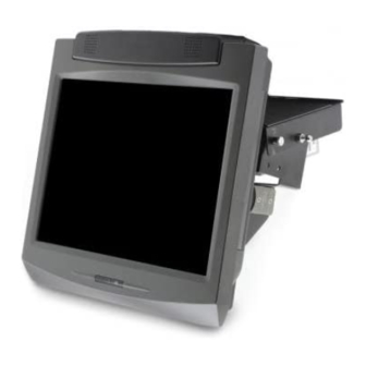
Product Overview Chapter 1: Introduction NCR’s RealPOS 70 (also referred to as NCR 7402) is a scalable, retail‐ hardened Point‐of‐Sale Solution with an intuitive touch screen interface designed for extended life cycles, stability, and superior availability. Engineered to thrive in the most demanding environments, the RealPOS 70 offers leading retailers in Hospitality, Convenience Stores and General Merchandise a POS platform that offers the greatest value for their POS investment. Unlike other POS solutions, the RealPOS 70 sets a new standard by offering an unprecedented combination of standard features including new embedded technology, ease of serviceability, and maximum configuration flexibility. The RealPOS 70 is available with a 12.1”, 15”, or 17” LCD display. 17" Model 15" Model 12" Model 21243... -
Page 20: Optional Configurations
Chapter 1: Product Overview Optional Configurations The NCR RealPOS 70 can be a free standing desktop, wall mounted, or it can be integrated with a peripheral tray to add further value and save valuable counter space. The integration tray supports a variety of NCR’s most popular peripheral options. Desktop Wall Mount Integration Tray 25415 ... -
Page 21: Model And Serial Numbers
The model/serial numbers can be found on two labels located behind the cable cover. A third label is located on the back of the Display Assembly. If the terminal came with an Operating System pre‐installed then there is also a Certificate of Authenticity label. Model Number Class:7402-1142 S/N:36309845 Date:21 November 2003 Serial Number Model Number NCR Corp Class:7402-1142 Unit Serial:36309845 Serial Number Model Number Serial Number NCR Corporation Atlanta, GA 30096 Made in Singapore Class 7402 This device complies with Part 15 of the FCC rules. - Page 22 Chapter 1: Product Overview The following table identifies the RealPOS 70 models. Model Description 7402‐1142 Intel 2.5 GHz Celeron, 12.1” Capacitive Touch Screen, 256MB Memory, 40GB Hard Disk, Integrated Stereo Speakers, US Power Cord, MSR 7402‐1151 Intel 2.5 GHz Celeron, 15” Capacitive Touch Screen, 256MB Memory, 40GB Hard Disk, Integrated Stereo Speakers, US Power Cord, MSR 7402‐1155 Pentium 4 2.4GHz processor, 15” Resistive Touch Screen, 512MB Memory, 80GB Hard Disk, Integrated Stereo Speakers, US Power Cord, No MSR Pentium 4 2.4GHz processor, 15” Capacitive Touch Screen, 7402‐1254 512MB Memory, 80GB Hard Disk, Integrated Stereo Speakers, US Power Cord, No MSR 7402‐1262 Intel 2.5 GHz Celeron, 17” Capacitive Touch Screen, 512MB Memory, 80GB Hard Disk, Integrated Stereo Speakers, US Power Cord, MSR ...
-
Page 23: Terminal Dimensions And Weights
Chapter 1: Product Overview Terminal Dimensions and Weights See the NCR RealPOS 70 Site Preparation Guide, B005‐0000‐1464. Hinged LCD The RealPOS 70 utilizes a top‐hinged LCD which allows extremely quick and easy motherboard access. The LCD can be completely removed if necessary for upgrades or repair. Functioning much like the hood of a car to gain access to the engine, the LCD has a security mechanism permitting it to be locked into place if desired. For procedures about how to open the cabinet, see the Installing Peripherals section in the Hardware Installation chapter. 20932 ... -
Page 24: Integrated Hardware
Chapter 1: Product Overview Integrated Hardware • Integrated 3‐Track ISO MSR (Optional) • Integrated Stereo Speaker Module • Integrated Infrared Sensor • PCMCIA (for wireless LAN) (Optional) • 128 MB, 256 MB, 512 MB, 1 GB non‐ECC Memory DIMMs • Hard Drive • Internal Compact Flash • 3M Touch Systems resistive or capacitive touch sensor • MSR (Optional) − ISO − JIS • Integrated Customer Displays (Optional) − Integrated 2 x 20 VFD − Integrated International APA (All Points Addressable) • Low‐Profile ATX Power Supply – 300 Watts (Optional) • LVDS TFT Display (Choice) • 12‐Inch – dual bulb enhanced brightness •... -
Page 25: Operating Systems
Chapter 1: Product Overview Operating Systems • DOS 6.22 • Windows NT Workstation • Windows 2000 Professional • Windows XPe • Windows XP (certified) • Linux (certified) ... -
Page 26: Key Service Advantages
Chapter 1: Product Overview Key Service Advantages Removable Motherboard Sled Complementing the hinged LCD is a motherboard tray mounting mechanism which allows the component to be easily removed without the use of tools. Removable Power Supply The 7402 utilizes an intuitive removable rear cover allowing easy access to the power supply. The Power Supply is mounted on a sled which permits removal or tool free service. Removable Hard Disk Removal of the back cover permits easy removal of the front cover, which permits tool‐free removal of the hard disk. ... -
Page 27: Hardware Module Descriptions
Chapter 1: Product Overview Hardware Module Descriptions Motherboard Processor/Chip Set The terminal uses an Intel architecture processor, which permits it to leverage existing software drivers and applications, as well as provide the greatest flexibility in choosing an operating system. This provides several other advantages: • Intel 2.5 GHz Celeron Processor, 128kB L2 Cache, 400 MHz front side bus • Intel 2.4 GHz P4 Processor, 512kB L2 Cache, 533 MHz front side bus • Capable of SW MPEG‐1 or MPEG‐2 playback at 30 frames per second with 22 kHz stereo audio (may be limited by OS constraints). • ® SoundBlaster ‐compatible audio • Expansion capabilities for optional features and future requirements (PCI bus and USB) System Memory The memory used is 266MHz DDR‐SDRAM on standard desktop 184 pin DIMMs at 2.5 volts. The board has two DIMM sockets. Release 1.0 supports 1GB maximum memory, which is the limit of the 852GM chipset. Larger memory configuration up to 2GB is supported with the 852GME chipset. Memory sizes include 128 MB, 256 MB, 512 MB, & 1 GB non‐ECC DIMMS. The 128MB DIMM used with release 1.0 contains 256Mb memory chips with 16Mx16 configuration. The other DIMMs used ... -
Page 28: 852Gme Graphics & Memory Controller Hub
1-10 Chapter 1: Product Overview 852GME Graphics & Memory Controller Hub • Supports CPU with 400 MHz FSB • Supports Desktop Intel Celeron or Pentium 4 processor with Northwood Core • Memory: DDR‐DRAM 200 or 266MHz, up to 2 double sided DIMMs, No ECC Support, 1GB maximum • Integrated graphics with VGA, LVDS LCD, and 1 digital video (DVO) port • Dual independent display with Windows multi‐monitor support • Shared memory architecture – 8‐64 MB video memory dynamically allocated from system memory • Hub interface to ICH4 south bridge at 266 Mb/s • IOQD (In order Queue Depth) = 12 North Bridge Features Release 1.0 includes the Intel 852GM GMCH (Graphics & Memory Controller Hub), which provides the following functions: • Supports CPU with 400 MHz FSB only • Supports Desktop CPU: P4 or Celeron •... -
Page 29: South Bridge Features
Chapter 1: Product Overview 1-11 Release 1.1 includes the 852GME board version, which adds support for: • CPU with 533 MHz FSB • DDR‐SDRAM up to 333MHz, up to 2GB maximum, ECC or non‐ ECC • Second digital video (DVO) port South Bridge Features The 7402 Motherboard uses the Intel ICH4 South Bridge, which provides the following functions: • Integrated Intel Audio (requires external codec) • Integrated 10/100 Ethernet controller (requires external 82562 PHY transceiver chip) • IDE controller with Primary & Secondary channels, each supporting master & slave drives; ATA‐100 support with automatic detection of 80‐conductor cable • USB Host controller – Four USB host controllers, six physical USB ports, USB 2.0 supported • PCI Bus Host Controller – up to 6 bus masters supported • LPC Bus Bridge Controller – interface to SuperIO & Trusted Platform Module • Hub Interface to North Bridge at 266Mb/sec • SMBUS (I2C) Controller – Interface Hardware monitor •... -
Page 30: Video Memory
1-12 Chapter 1: Product Overview Video Memory Shared memory architecture uses 8‐64 MB video memory, with Dynamic video memory allocation (DVMT). BIOS Memory The 7402 includes 512KB of Flash BIOS and supports up to 1MB Flash parts. A DMI area in the BIOS ROM stores system information about the 7402, such as serial number and model number. Platform software detects board version via device ID of key components on the board. There is no board ID EEPROM. Video The 7402 uses integrated graphics in the 852GM and 852GME chip. Graphics Controller Architecture • Shared memory architecture uses 8‐64MB video memory, with Dynamic video memory allocation (DVMT) • Motion compensation for MPEG‐2 support • Software DVD playback at 30 frames/second full screen • Video overlay support • 2D Graphics engine includes 128 bit BLT engine and color space conversion • 3D Graphics engine includes DirectX support, 16/24 bit Z‐buffering, Enhanced texture functions, Double and triple render buffer support, 16 & 32 bit color, maximum 3D resolution of 1600x1200 @ 85Hz • Dual independent display pipelines – appear as independent display devices to the OS ... - Page 31 Chapter 1: Product Overview 1-13 Graphics Output Devices Video outputs: VGA CRT (15 pin DB‐9 connector), DVI‐I external monitor, and LVDS LCD (internal) • VGA CRT support up to 1600x1200x24 bit @ 85Hz • Integrated LVDS transmitter: Supports up to 1400x1050@ 60Hz single or dual channel dual channel LVDS flat panel, with LVDS frequency up to 112MHz. • Generates LCD power sequencing and backlight inverter control signals • Bi‐Linear panel fitting (stretching) • Digital video (DVO) port used to drive DVI transmitter component • Second DVO port (852GME only), which is used for display options on other NCR platforms • DVI external monitor support up to 1600x1200 @ 60Hz, Compliant with DVI Specification 1.0 • Dual independent display support with Windows multi‐monitor support (Extended Desktop and Simultaneous modes) VGA+DVI, VGA+LVDS, LVDS+DVI Extended Desktop mode only) supported, any device can be selected as primary. Analog Monitor DVI‐I is provided as a convenience for users with analog monitors having a DVI connector. DVI‐I means an analog VGA signal is present on the DVI connector, along with the digital DVI signals. On the 7402, the analog DVI‐I signal is the same as that sent to the VGA 15 pin connector. A VGA monitor may be connected to either the VGA 15 pin connector or the DVI‐I connector, but not both at the same time. ...
-
Page 32: Usb Port Functionality
1-14 Chapter 1: Product Overview LCD Support Intel generated a specification for integrated LCD support in PC systems, called Common Panel Interface Specification (CPIS). The 852GM/GME graphics controller uses the LCD interfaces. LVDS signals are brought out to a 50 pin header on the motherboard. Although CPIS specifies an LCD connector the 7402 does not use it because it does not support 24‐bit color LCD. DVI Interface The DVI supports NCR display peripherals such as the 5964 as well as standard PC digital monitors. USB Port Functionality The motherboard supports six USB ports with the following characteristics: • USB v.2.0 (EHCI) and Intel Universal HCI v.1.1 (UHCI) compatible • Three independent UHCI host controllers plus the EHCI , all can map to any physical port • Each Host Controller has its own root hub • Integrated physical layer transceivers with over‐current detection status on USB inputs • Legacy PS/2 keyboard and PS/2 mouse support so that legacy software can run transparently in a non‐USB‐aware operating system environment. • Permits hot plug and play and isochronous peripherals to be inserted into the system with universal driver support. Two standard Type A USB ports, and two 12V Powered USB ports ... -
Page 33: Ethernet Lan
Chapter 1: Product Overview 1-15 Ethernet LAN The 7402 uses the Intel 82562EX Platform LAN component (10/100 PHY/transceiver used with ICH4 integrated LAN controller), which features: • Compliance with Advanced Configuration and Power Interface and PCI Power Management standards • Support for wake‐up on interesting packets and link status change • Support for remote power‐up using Wake on LAN (WOL) technology • Support of Wired for Management (WfM) Rev 2.0 • Transmit and Receive FIFOs 3kB each • Backward compatible software with 82557, 82558 and 82559 (used on previous NCR products) • TCP/UDP checksum off load capabilities • Support for Intel’s Adaptive Technology (robust operation at 100Mb/s) • Intel PXE (network boot) support incorporated into system BIOS • RJ‐45 LAN connector with speed and link LED, and integrated magnetics for better cost/performance Integrated Audio The digital audio link in the ICH4 supports the Audio Codec ’97, Revision 2.3 specification, which includes support for three codecs with independent PCI functions for audio and modem. Note: The integrated Modem is not supported. Microphone input and left and right audio channels are supported for a high quality, two‐speaker audio solution. ... -
Page 34: Fan Connectors
1-16 Chapter 1: Product Overview The ICH4 supports up to six channels of PCM audio output (full AC3 decode). Six‐channel audio consists of Front Left, Front Right, Back Left, Back Right, Center, and Subwoofer, for a complete surround‐ sound effect. ICH4 has expanded support for three audio codecs on the AC‐link. The 7402 motherboard provides a single codec for Left and Right stereo sound. Surround sound is not supported. An amplifier integrated on the motherboard allows direct drive of stereo speakers, up to 3 Watts/channel. Intel provides Windows and Linux drivers for the integrated audio. Under DOS there is SoundBlaster compatibility. Audio Outputs: • A triple stack audio connector on the rear I/O with Line in (top), Speaker out (middle), and Mic in (bottom) on 3.5mm stereo jacks. • An internal 14 pin header as defined by Embedded ATX, implementing Line out (amplified), Speaker out, and Mic in. Plugging a cable into the Speaker out or Mic in ports on the rear I/O disables that functionality on the internal header. A piezo transducer on the motherboard provides basic PC beep functionality under DOS, and also for other OS when there are no speakers connected. The PC beep signal is connected to the audio codec to allow PC beep sounds to play through the speakers when these are present. Fan Connectors The motherboard has three fan connectors. One is reserved for the CPU fan. The power supply fan speed output is connected to a second fan connector, which is used to monitor power supply fan health. All fan connectors are +12Vand are intended for fans with 300mA typical current draw. ... -
Page 35: Cash Drawer Support
Chapter 1: Product Overview 1-17 The motherboard has hardware support for variable speed CPU fan, using the LM85 monitor. Variable speed fan can lower system noise levels, reduce dust ingress, and improve fan life. Fan speed control is via PWM signals generated by the LM85. Cash Drawer Support The 7402 Terminal controls the cash drawer through a cash drawer Kickout connector on the back of the terminal (Retail Daughter Card), or through the cash drawer Kickout connector on the transaction printer. The terminal can be configured with 0, 1, or 2 cash drawers. The first drawer is attached to the terminal through a cable with an RJ‐ 45 connector. A second drawer can be connected using a ‘Y’ cable. Note: A single Open/Close status signal is shared with both drawers. Therefore, it is not possible to determine which cash drawer is open. 21366 The MSR interface supports a maximum of 3 tracks of magnetic stripe information for support of ISO format cards. ... -
Page 36: Retail Daughter Card
1-18 Chapter 1: Product Overview Retail Daughter Card • Cash Drawer Port (supports two drawers via a Y‐cable) • Touch Controller (3M EXII) for Resistive & Capacitive Touch Sensors • NCR 2 Generation Trigantor MSR Controller with Wedge I/F • 24 V Powered USB Port • Motion Sensor I/F PCI Boards PCI Riser Board The PCI Riser Board is a single‐slot board, which supports the custom 7402 PCI boards. PCMCIA Adapter Board This PCI board supports one Type 2 PCMCIA card. The PCMCIA socket supports 12V, 5V and 3.3V cards and is switched automatically by the Texas Instrument TPS2226A power switch. All cards are internally buffered to allow hot insertion and removal. The PCI card has an internal data path, which allows the host to access 8‐, 16‐, and 32‐bit cards using full 32‐bit PCI cycles for maximum performance. Pipeline architecture provides an unsurpassed performance level with sustained bursting. This card is register compatible with the Intel 82365SL‐DF and 82356SL. Dual RS-232 Adapter This PCI board has two 16C550 compatible serial ports, which are ... -
Page 37: Storage Media
Chapter 1: Product Overview 1-19 Storage Media HARD DISK DRIVE The 7402 supports one 3.5 inch, Ultra DMA 100 IDE hard disk drive. The drive is located in the front of the base. It has the following performance characteristics: • RPM: 7200 • Size: 40/80 GB • 2 MB SDRAM Cache Buffer Compact Flash The 7402 supports Compact Flash through the IDE interface. The adapter board is located on the Retail Daughter Card Bracket. The compact flash must be set for Master Mode. ... -
Page 38: Operator Display
1-20 Chapter 1: Product Overview Operator Display The motherboard, through the LVDS Adapter Board, supports an integrated Display Head with an LVDS TFT LCD panel. LCD Panel The 7402 provides three operator display options. • 12.1” Dual bulb LVDS TFT display (Sharp LQ121S1DG41) • 15” Dual bulb LVDS TFT display (Sharp LQ150X1LGN2H). • 17” Quad bulb LVDS TFT display (Sharp LM170E01‐A4). The display head has the following characteristics: • LVDS interface used to control the LCD • RS‐232 interface used to communicate with the touch screen controller (located on Retail Daughter Card) • The display head draws a maximum of 1.5A from the powered RS‐ 232 interface LVDS LVDS (Low Voltage Differential Signaling) is an improvement over the traditional parallel interface. LCD image data is sent on 4 pairs of wires rather than on 20 individual data lines. The Intel chipset drives LVDS directly with no additional logic required. Advantages of LVDS include: • Reduces LCD Cable complexity • Dramatically reduces radiated emissions • Improves robustness of display signal timing • Supports longer cable length up to several feet if required ... -
Page 39: Inverter
Chapter 1: Product Overview 1-21 Inverter An inverter is used to drive the CCFL (cold cathode fluorescent) backlights of the LCD. Since the inverter is matched to the LCD, the 12.1”, 15”, and 17” displays have different inverters. Inverter output power is approximately 9 watts for the 12.1” display, 13 watts for the 15”, and 15 watts for the 17”. The inverter mounts to the back of the LCD bracket near the PCI slot. A cover protects personnel and surrounding circuitry from the high voltage required to drive the backlight tubes. The 17 inch inverter mounts directly behind the LCD panel, under the rear bezel. Touch Screen The 7402 supports either a five‐wire resistive Touchscreen or a Capacitive Touchscreen. A hardware jumper on the Retail Daughter Card selects resistive or capacitive mode. All applications and diagnostics use the touch interface for user interaction. The touch screen glass completely covers the LCD display and is mounted directly in front of the LCD, behind the front plastic bezel. The MicroTouch EX II chipset is used to control the Touchscreen, which is connected to the Retail Daughter Card through an internal RS232 cable and interface. The Touchscreen is designed to be easily replaced in case of damage or failure. ... -
Page 40: Adjusting The Display Angle
1-22 Chapter 1: Product Overview Adjusting the Display Angle The display can be adjusted from 15 – 90 . 1. Unlock the Hinge. 2. Tilt the Display Module to the desired position. 3. Lock the Hinge. CAUTION: Do not force the display past the maximum rotation positions. This can result in damage to the aluminum casting. Turn Counter-clockwise to Unlock Turn Clockwise to Lock 21893 ... -
Page 41: Integrated Customer Display
Chapter 1: Product Overview 1-23 Integrated Customer Display The 7402 supports an integrated Customer Display, which is located on the top of the display head, facing the back of the unit. There are two types: • 2 x 20 VFD • All Points Addressable Display 2 x 20 VFD The 2 x 20 VFD Customer Display module consists of a VFD with 2 rows of 20 5x8 dot matrix characters, RS‐232 interface, driver circuitry, DC to DC/AC converter, and character generator. All Points Addressable Display The All Points Addressable Customer Display module consists of a 128 x 64 dot matrix graphic VFD, RS232 interface, DC to DC/AC converter, and a character generator. The module is capable of displaying 64 luminance levels and 4 grayscale levels. ... -
Page 42: Motion Sensor
1-24 Chapter 1: Product Overview Motion Sensor The 7402 supports a motion sensor for system wakeup based on nearby activity. This is a photodiode sensor which detects changes in ambient light levels. The hardware generates an input signal to the motherboard which can be polled or used to generate interrupts depending on software architecture (NCR‐supplied software and operating system software can both use this interface if configured correctly). The 7402 does not support wakeup from soft off via the motion sensor. However, wake from standby or screen saver are possible, and NCR driver software allows customer applications to directly use the motion sensor. The photodiode mounts behind a clear plastic lens below the LCD panel. The circuitry is optimized for normal room lighting conditions. Excessive bright light or darkness can reduce its effective range. Typically motion within 2‐4 feet of the system causes a wakeup. Power Indicator A green LED power indicator is located below the LCD near the motion sensor. The LED illuminates whenever the system power supply is active. Thus the power indicator shows that the unit is On or in Standby. Speakers The 7402 has stereo speakers integrated into the top of the display head above the LCD panel. These connect to the motherboard internal audio header. Nominal audio power is 3W per channel, which provides full PC audio capability. For higher‐fidelity sound, external speakers can be connected to the external audio jack on the I/O bracket. The integrated speakers are muted in hardware whenever a cable is plugged into the external audio jack. There is only enough power available to drive one set of speakers. ... -
Page 43: Biometrics Module
Chapter 1: Product Overview 1-25 Biometrics Module This feature adds an integrated Biometrics module for the 7402 terminal, which provides fingerprint recognition capabilities. Biometrics Module 23616... -
Page 44: Power Management
1-26 Chapter 1: Product Overview Power Management The BIOS supports the supports the Advanced Configuration and Power Management Interface (ACPI) 1.1 specification. The 7402 supports the system power states defined by ACPI: G3 Mechanical Off A computer state that is entered and left by a mechanical means Example: Turning off the system’s power through the movement of a large red switch. Various government agencies and countries require this operating mode. It is implied by the entry of this off state through a mechanical means that no electrical current is running through the circuitry and that it can be worked on without damaging the hardware or endangering service personnel. The OS must be restarted to return to the Working state. No hardware context is retained. Except for the real‐ time clock, power consumption is zero. G2/S5 Soft Off A computer state where the computer consumes a minimal amount of power. No user mode or system mode code is run. This state requires a large latency in order to return to the Working state. The system’s context will not be preserved by the hardware. The system must be restarted to return to the Working state. It is not safe to disassemble the machine in this state. ... -
Page 45: G1 Sleeping
Chapter 1: Product Overview 1-27 G1 Sleeping A computer state where the computer consumes a small amount of power, user mode threads are not being executed, and the system appears to be off (from an end user’s perspective, the display is off, and so on). Latency for returning to the Working state varies on the wake environment selected prior to entry of this state (for example, whether the system should answer phone calls). Work can be resumed without rebooting the OS because large elements of system context are saved by the hardware and the rest by system software. It is not safe to disassemble the machine in this state. G0 Working A computer state where the system dispatches user mode (application) threads and they execute. In this state, peripheral devices (peripherals) are having their power state changed dynamically. The user can select, through some UI, various performance/power characteristics of the system to have the software optimize for performance or battery life. The system responds to external events in real time. It is not safe to disassemble the machine in this state. Under the G1 sleeping state ACPI defines levels of system sleep state support. The 7402 supports the following sleeping states: • S0: Normal Powered‐On state • S1 (Standby): The S1 sleeping state is a low wake latency sleeping state. In this state, no system context is lost (CPU or chip set) and hardware maintains all system context. The 7402 does not support the S2, S3 (Suspend to RAM), or S4 (Suspend to Disk) sleeping states. Reference the ACPI Specification for details. Peripherals: ACPI defines power states for peripherals which are separate from the system power state. The device power states range from D0 (fully‐on) to D3 (off) It is the responsibility of the driver developer for each peripheral to define and support the available power states. ... -
Page 46: Wake On Lan
• The driver is set to Wake on LAN via Magic Packet (i.e. specific MAC address). • The 7402 must not be powered down or shut down, but rather be put into Standby. • The NCR Retail prescribed method for waking a terminal is to use FitClient. • There are third party or freeware programs that can send a Magic Packet. If you are not using the NCR Gold Drive: The LAN Driver Advanced Settings must be modified in order for Wake on LAN to work. The required modifications are: 1. Execute the Intel Proset Utility from the Control Panel. 2. Choose the Advanced tab. Choose the item Enable PME and change the setting from No Action to Hardware Default. Choose the item Wake On Settings and change the setting from OS Controlled to Wake on Magic Packet. 5. The 7402 must not be powered down or shut down, but rather be put into Standby. 6. The NCR Retail prescribed method for waking a terminal is to use FitClient. 7. There are third party or freeware programs that can send a Magic Packet. ... -
Page 47: Compatibility
Chapter 1: Product Overview 1-29 Compatibility LAN Communications The software associated with the terminal systems conform to the following standards: • Network Driver Interface Specification (NDIS 4) • IEEE 802.3 & 802.3u CSMA/CD (10/100 MB/s Ethernet) • IEEE 802.2 Link Level Control (LLC) • TCP/IP Application Programmability The software associated with the terminal systems conform to the following standards: • OLE for Retail POS 1.4 • JavaPOS for Retail 1.4 • HTML 4.0 • ECMA Script • Java Development Kit 1.1.3 Operating System Information The software associated with the terminal systems conform to the following standards: • Microsoft Windows NT • Microsoft Windows 2000 ... -
Page 48: System Configuration Diagram
1-30 Chapter 1: Product Overview System Configuration Diagram 5964 Touch Screen 5942 RS-232 RS-232 (Powered) (24 V) 7167 7197 Retail Daughter Card 5932 USB 7402 Motherboard Cash 2nd Drawer (Y-Cable) Drawer Parallel 2189/2183 PS/2 5932 Big Ticket Mouse RS-232 PS/2 RS-232 (12 V) USB (Powered) -
Page 49: Chapter 2: Installing The Terminal
Installing the Terminal Chapter 2: Introduction The 7402 is fully assembled at the factory. This chapter discusses how to install a standalone terminal. If you are installing the 7402 in an integrated configuration see the Installing the Terminal in an Integrated Configuration chapter. Installation Summary • Remove the terminal from the shipping packaging and verify the hardware configuration. Connect the peripheral and communication cables. • Connect the peripheral and communication cables. • Attach the Power Cord to the system and to an AC power source. • Connect a USB keyboard to the terminal. This is needed to accept the license agreement during system boot because the touch screen is not available at that time. • After power is applied to the terminal the Power‐up self‐tests run to verify basic functionality. • ROM‐based setup should be used to configure network options. Full configuration depends upon the system server and the management web site. ... -
Page 50: Installation Restrictions
Chapter 2: Installing the Terminal Installation Restrictions • Before installing the terminal, read and follow the guidelines in the NCR RealPOS 72 Site Preparation Guide (B005‐0000‐1464) and the NCR Workstation and Peripheral AC Wiring Guide (BST0‐2115‐53). • Install the terminal near an electrical outlet that is easily accessible. Use the power cord as a power‐disconnect device. • Do not permit any object to rest on the power cord. Do not locate the terminal where the power cord can be walked on. • Use a grounding strap or touch a grounded metal object to discharge any static electricity from your body before servicing the terminal. • If the power cord is replaced, it must be replaced with the same type of cord with the protective shroud. • Do not route the power cord through openings with sharp edges. Warning: This unit contains hazardous voltages and should only be serviced by qualified service personnel. Warning: DO NOT connect or disconnect the transaction printer while the terminal is connected to AC power. This can result in system or printer damage. Warning: DO NOT connect or disconnect any serial peripherals while the terminal is connected to AC power. This can result in system or printer damage. Warning: The NCR 742 terminals must be mounted securely to prevent a hazard. They must be installed in accordance with local building codes. The post or wall on which the unit is mounted should be able to withstand four times the weight of the unit. ... -
Page 51: Peripheral Cable Routing
Chapter 2: Installing the Terminal Peripheral Cable Routing The peripheral cables are routed down through the base and out the rear of the unit. They are secured internally with a Cable Clamp. Cable Clamp 21025... -
Page 52: Installing Peripherals
Chapter 2: Installing the Terminal Installing Peripherals Caution: Disconnect the AC power cord before disassembling the terminal. The ON/OFF switch does NOT remove power to the unit. Use appropriate Electro Static Discharge procedures during this modification. The AC Power Cord can be disconnected from the wall or from the bottom of the terminal. Power Cord 21047 ... -
Page 53: Accessing The Cable Connectors
Chapter 2: Installing the Terminal Accessing the Cable Connectors This section describes how to install transaction printers and other peripherals supported by the 7402. The cable connectors are located behind the Cable Cover. 1. Unlock the Hinge and tilt the Display Module to the back. 2. Remove the Cable Cover. a. Remove the screw from the Cable Cover. b. Press down on the two plastic Cable Cover Release Tabs and slide the cover forward. Front Cover Latches Screw 20931 ... -
Page 54: Cable Connector Identification
Chapter 2: Installing the Terminal Cable Connector Identification 1. Connect the peripheral and LAN cables. The illustration identifies the peripheral connectors on the terminal. See the sections that follow for specific installation instructions for each of the peripherals. 24V USB Cash Drawer RS232/D Line In RS232/E RS232/F Mouse Line Out RS232/B Parallel Kybd RS232/A 12V USB 12V USB 20917 Note: RS232/1, RS232/2, and RS232/4 can be powered ports. They are enabled via hardware straps on the Motherboard. RS232/3 is an internal port that is dedicated to the Touch feature. 2. After installing the peripheral and LAN cables replace the cable cover. ... -
Page 55: Ps/2 Keyboard/Mouse Cable Connections
Chapter 2: Installing the Terminal PS/2 Keyboard/Mouse Cable Connections The 7402 has dedicated PS/2 connectors to support both a keyboard and mouse. 24V USB Cash Drawer RS232/D Line In RS232/E RS232/F Mouse Line Out RS232/B Parallel Kybd RS232/A 12V USB 12V USB PS/2 Mouse (Green) PS/2 Keyboard (Purple) 21028a Mouse Installation Restriction If you are running Windows NT you must make the following Registry ... -
Page 56: Opening The Display Cabinet
Chapter 2: Installing the Terminal Opening the Display Cabinet 1. Remove the screw that locks the Display Assembly firmly closed. Screw 21024 ... -
Page 57: 12.1" And 15" Models
Chapter 2: Installing the Terminal 2. Open the Display Cabinet. There are two styles of latches that are used to secure the Display Cabinet. 12.1” and 15” Models Press the Display Latch as shown and then open the Display Assembly. Diaplay Latch 21026... -
Page 58: 17" Models
2-10 Chapter 2: Installing the Terminal 17” Models Rotate the latches as shown and then open the Display Assembly. Diaplay Latches 22025... -
Page 59: Powering Up The Terminal
Chapter 2: Installing the Terminal 2-11 Powering Up the Terminal Terminal On/Off Switch The Terminal On/Off Switch is located behind the Cable Cover. There is a hole in the Cable Cover that you can insert a small object to access the switch, or you can remove the Cable Cover to gain access to the switch. This is a logic switch only, which has two states. • Last State – the terminal resumes the last power state when power is restored. • Power On – the terminal powers on when power is restored. Power Switch 20989 ... - Page 60 2-12 Chapter 2: Installing the Terminal The power state can be set to user preference in the BIOS Setup. Change the After Power Failure parameter in the Boot Menu. By default the Terminal Power Switch is set to Last State. Note: There is also a On/Off Power Switch located on the Power Supply Power. Power Supply AC On/Off Switch 21347 After power is applied to the terminal the Power‐up self‐tests run to verify basic functionality. ROM‐based setup should be used to configure network options. Full configuration depends upon the system server and the management web site. ...
-
Page 61: Calibrating The Touch Screen
Chapter 2: Installing the Terminal 2-13 Attach the Power Cord to the system and to an AC power source. Power Cord 21047 Calibrating the Touch Screen See the Touch Screen Calibration chapters. ... -
Page 62: Out-Of-Box Failures
2-14 Chapter 2: Installing the Terminal Out-of-Box Failures During installation if there is an Out of Box failure, the defective component will be replaced. The defective part number must be identified by trained service personnel. If required, contact your Equipment Provider, NCR Customer Service or your Service Provider to diagnose the failure to the component level. A replacement component can be acquired by contacting the NCR Customer Satisfaction Hotline between the hours of 8AM and 5PM EST, Monday – Friday: • 1‐800‐528‐8658 (USA) • 770‐623‐7400 (Internationally) or E‐mail: CustomerSat.Retail@NCR.com Please have the following information available: 1. NCR Order Number (Order # on label of box) 2. Product Model Number 3. Unit Serial Number 4. NCR part number of defective/missing/wrong component 5. Number of Units Staged/Installed 6. Organization Code 7. Shipping Address with Contact Name & Phone Number ... -
Page 63: Chapter 3: Touch Screen Calibration - Windows (Mt 7.12)
Chapter 3: (MT 7.12) Note: This chapter discusses calibration procedures using MicroTouch, Version 7.12. General Guidelines Observe for the following Touch Screen calibration guidelines: • Calibrate the touch screen as part of the initial installation. • Recalibrate whenever the terminal is moved to a new location. • Recalibrate after replacing any component in the terminal. • Recalibrate whenever a customer reports a touch screen problem. • Recalibrate if you switch to a new screen resolution Use the TouchWare utilities to perform the following procedures: • 2‐Point Calibration • Cursor Stabilization • 25‐Point Linearization • Restore Defaults Procedure The TouchWare utilities are available on the NCR Gold Drives for WinNT, Win2K, WinXP Pro and WinXPe. Application software can possibly generate a dialog box from the Touch Driver, with the message that the touch screen needs to be recalibrated. If the screen appears to be working normally, then this message can be ignored. There will be a check box labeled Do not show this message again. Make sure this box is checked. ... -
Page 64: Considerations When Replacing Or Re-Imaging The Hard Drive
Do you want to use the internal linearity data? You should ALWAYS answer this question with Yes and then perform the 2‐Point Calibration procedure. If still have a calibration problem, see the Windows or DOS Calibration Flowchart to resolve it. Installing the Touch Software This software is available on the NCR Web Site. http://www.ncr.com 1. At this site, select the Support tab. Select Drivers and Patches → Retail Support Files → NCR RealPOS and SelfServ Peripherals → Displays → 5964. Download the 5964 15” Touch Software Note: This driver is backward compatible. If you have an earlier version installed then first uninstall it using the Add/Remove Programs applet in Windows and then install the new software. 4. Extract the installation files into to a working directory on the host ... - Page 65 Chapter 3: Touch Screen Calibration – Windows (MT 7.12) 7. When prompted to choose the installation type choose Typical. Note: If you do not want the cursor to display choose Custom (see the Hiding the Cursor section). 8. After completing the software installation, perform a calibration procedure (see Touch Calibration Procedures section in this chapter). ...
-
Page 66: Hiding The Cursor
Chapter 3: Touch Screen Calibration – Windows (MT 7.12) Hiding the Cursor In some applications, it is desirable to hide the cursor. The MT 7.12 driver provides a blank cursor file to hide the cursor. 1. During installation, select either the Full or Custom installation option. If you select Custom, select to the Utilities and Tools option box, which contains the Blank Cursor option. This puts a file, BLANK.CUR, into the C:\Program Files\MT7 directory. Select Next. ... - Page 67 Chapter 3: Touch Screen Calibration – Windows (MT 7.12) 3. Copy the BLANK.CUR file into your Windows Cursors directory at C:\Windows\Cursors. Select Start → Control Panel → Mouse. 5. Select the Pointers tab. 6. Select the Browse button. ...
- Page 68 Chapter 3: Touch Screen Calibration – Windows (MT 7.12) 7. Browse to the C:\Windows\Cursors directory (if you are not already there) and select the BLANK.CUR file. Select Open. 8. Select OK to set the hidden cursor. 9. After completing the software installation, perform a calibration procedure (see Touch Calibration Procedures section in this chapter). ...
-
Page 69: Other Serial Devices Do Not Function
Chapter 3: Touch Screen Calibration – Windows (MT 7.12) Other Serial Devices Do Not Function The touch controller does not support plug and play functionality. The MT 7.12 driver must search for this device. This search process can interfere with other serial devices on the system. To disable the serial search function perform the following. Caution: Editing registry values may alter the performance of your system or render in inoperable. Create a backup of your Windows system registry file before making any changes to it. Refer to Microsoft Windows Help for instructions on handling registry files. 1. Stop the MT Serial Search service. Select Start → Control Panel → Administration Tools → Services. Right‐click on the MT7 Serial Search service and select Stop. ... - Page 70 Chapter 3: Touch Screen Calibration – Windows (MT 7.12) 2. Stop the TwMonitor.exe process. Press Ctrl-Alt-Del and select Task Manager. b. Select the Processes tab. Select TwMonitor and then select the End Process button. d. Select Yes at the warning message. ...
- Page 71 Chapter 3: Touch Screen Calibration – Windows (MT 7.12) 3. Add serialportsearch Key to the registry. a. Select Start → Run. b. Enter regedit and select OK. c. Browse to: hkey_local_machine/system/currentcontrolset/services/ twtouch/parameters Select Parameters → New → String Value. ...
- Page 72 3-10 Chapter 3: Touch Screen Calibration – Windows (MT 7.12) e. Enter the new String Value name – serialportsearch. f. Right‐mouse click serialportsearch and then select Modify. ...
- Page 73 Chapter 3: Touch Screen Calibration – Windows (MT 7.12) 3-11 g. Assign the new String Value – COM3 and select OK. 4. Close the registry editor and reboot the system. ...
-
Page 74: Touch Calibration Procedures
3-12 Chapter 3: Touch Screen Calibration – Windows (MT 7.12) Touch Calibration Procedures Use the TouchWare utilities to perform the following procedures: • 3‐Point Calibration • 25‐Point Linearization • Restore Defaults The TouchWare utilities are available on the NCR Gold Drives for WinXP Pro, WinXPe, and WePOS. Note: Customers who are running a Windows application should always use TouchWare to calibrate. Do not boot into DOS and run Microcal. Application software can possibly generate a dialog box from the Touch Driver, with the message that the touch screen needs to be recalibrated. If the screen appears to be working normally, then this message can be ignored. There will be a check box labeled Do not show this message again. Make sure this box is checked. ... -
Page 75: Calibration Flow Chart
Chapter 3: Touch Screen Calibration – Windows (MT 7.12) 3-13 Calibration Flow Chart The following flow chart shows the proper sequence to perform the various calibration procedures. Perform 3-Point Calibration Note: When you re-image the hard drive, you may get the following error message: Is Calibration Correct? Controller's internal linearity data differs from its (Test by touching all 4 corners last saved linearity data. -
Page 76: 3-Point Calibration
3-14 Chapter 3: Touch Screen Calibration – Windows (MT 7.12) 3-Point Calibration Note: The Linearization procedure should be performed before calibration if either the Touch Screen Sensor or the Controller Board is replaced. → → → Select Start Programs MicroTouch MT 7.12 Control Panel 2. Select the Main tab. 3. Select the Calibrate button. ... - Page 77 Chapter 3: Touch Screen Calibration – Windows (MT 7.12) 3-15 4. Three targets are displayed, one at a time. Touch the center of the green target in the lower left‐hand corner of the screen. Hold down for a couple of seconds and then liftoff. This position calculates at liftoff, at which time the target turns red. 25408 For best results: • Face the monitor directly. • Perform the calibration in the position (sitting or standing) that you normally expect to use the touch screen. • Touch the calibration target firmly and precisely with your fingertip. During calibration, be careful to keep your fingernails and other fingers away from the touch screen as you touch each target. 5. Repeat this procedure for the second target. 6. Touch the third target to complete the calibration. This point registers immediately when you touch the screen. ...
- Page 78 3-16 Chapter 3: Touch Screen Calibration – Windows (MT 7.12) 7. A dialog box asks if you want to Test, Accept, or Cancel this calibration. Select Test. (Optional at this time) Calibration completed successfully. Do you want to test the calibration? Cancel Test Accept 25250 8. Test the calibration on the draw screen. • Touch random locations on the screen and verify the results. • Drag your finger across the screen and check that the line follows your movements. • Touch each corner and along the edges of the screen. Verify that you can reach the full image area of the screen. • Recalibrate the touch screen if you are not satisfied with the ...
- Page 79 Chapter 3: Touch Screen Calibration – Windows (MT 7.12) 3-17 10. If you are satisfied with the calibration results, select Yes. It is recommended that you calibrate again if vertical and horizontal lines (except around the outer bezel) are more than 6mm from the touch point. Are you satisfied with the results? 25406 ...
-
Page 80: Linearization
3-18 Chapter 3: Touch Screen Calibration – Windows (MT 7.12) Linearization The Linearization procedure should be performed if either the Touch Screen Sensor or the Controller Board is replaced. Note: On new terminals the display is linearized at the factory and performing the linearization procedure can result in loss of the factory settings and reduced performance Under the Tools tab select the Advanced Options button. ... - Page 81 Chapter 3: Touch Screen Calibration – Windows (MT 7.12) 3-19 Select the Enable manual linearization option box and then OK. ...
- Page 82 3-20 Chapter 3: Touch Screen Calibration – Windows (MT 7.12) 3. Select the Controller tab. 4. Select the Linearize button to begin the linearization process. Note: If you press Escape or do not touch the screen within 20 seconds, the system automatically cancels the linearization process with no changes to the current settings. ...
- Page 83 Chapter 3: Touch Screen Calibration – Windows (MT 7.12) 3-21 11. A series of 25 targets are displayed, one at a time. Touch the center of the first green target and hold it until the target turns red. Repeat this procedure with each successive target. The image below shows the screen after 13 targets have been touched. For best results: • Face the monitor directly. • Perform the calibration in the position (sitting or standing) that you normally expect to use the touch screen. • Touch the calibration target firmly and precisely with your fingertip. During calibration, be careful to keep your fingernails and other fingers away from the touch screen as you touch each target. ...
- Page 84 3-22 Chapter 3: Touch Screen Calibration – Windows (MT 7.12) 12. A dialog box asks if you want to Test, Accept, or Cancel this calibration. Select Test. You can test the linearization by touching the 16 verification targets. Do you want to proceed? 25409 5. Select Yes to continue. 6. Touch the center of the yellow target. 25410 7. If you successfully touch the target, it turns green. If your touch misses the target, the target turns red and returns a percentage error number. If the linearization is not within acceptable tolerances ...
-
Page 85: Other Controls
Chapter 3: Touch Screen Calibration – Windows (MT 7.12) 3-23 Other Controls This section discusses other controls and information fields that are available in the Software Control Panel besides Calibration and Linearization. Main Tab Controller ID This field identifies the controller on your system. Controller Type This field displays the type of controller on your system. This data may be useful for Technical Support issues. Firmware Version These digits represent the version number and revision level of the touch screen controller firmware. ... -
Page 86: Touch Settings Tab
3-24 Chapter 3: Touch Screen Calibration – Windows (MT 7.12) Touch Settings Tab The controls in this tab enable you to customize the responses of your touch screen. You can change the way the system responds to your touch, add a right‐click tool to your desktop, tell your system to beep on touch, and define the double‐click speed and screen area of your touch. ... -
Page 87: Touch Modes
Chapter 3: Touch Screen Calibration – Windows (MT 7.12) 3-25 Touch Modes The available Touch Mode options are Drawing, Touchdown, and Liftoff. Drawing Mode (Default) Drawing Mode is most useful for draw, paint, illustration, and graphics applications. Touching the screen is equivalent to pressing and holding down the mouse button. Lifting off is equivalent to releasing the mouse button. To Click Touch the object, lift off the screen. To Double-Click Touch the object twice quickly To Drag Touch the object, slide your finger to the new location and then lift it off the screen. Touchdown Mode Touchdown Mode enables you to create an immediate button action when you touch the screen. You can leave your finger on the screen but only a single touch is registered. Touching the screen is equivalent to pressing and releasing the mouse button. This mode is best for button‐based applications, such as a calculator. Drawing or dragging is not supported in this mode. Liftoff Mode Liftoff Mode enables you to position the cursor where you want before ... -
Page 88: Right-Click Tool
3-26 Chapter 3: Touch Screen Calibration – Windows (MT 7.12) Right-Click Tool This option places an icon on the desktop (always on top of your application) that permits you to select which mouse button to activate on touch. This works for the next click action only. Control returns to the left mouse button after that. You can position the icon anywhere on your desktop by selecting and holding it until the 4‐pointed arrow appears, and then dragging it to wherever you desire. Left button is typically used for normal select and normal drag. Right button is typically used for applet properties, such as context menu and special drag. Touch Sound This is used to select audible beep on touchdown, liftoff, or no beep at all. Click on the Beep button to select the appropriate option for your application. The default setting is no beep on touch (Beep off). Double-Click Speed Note: Not available on Windows® CE Double‐click defines how quickly you must touch the screen for the system to interpret your actions as a double‐click. Set the double‐click speed in the slow to medium range for optimum performance with a touch screen. Touch the globe twice to test the Double‐Click Speed setting. If the globe begins to spin, the touch screen recognized your touch as a double‐click. Note: Changing this setting also affects the double‐click setting of the mouse. ... -
Page 89: Double-Click Area
Chapter 3: Touch Screen Calibration – Windows (MT 7.12) 3-27 Double-Click Area Note: Not available on Windows® CE Double‐Click Area defines the space in which you must touch the screen for the system interpret your actions a s double‐click. Set the Double‐Click Area in the medium to high range for optimum performance with a touch screen. Touch the globe twice to test the Double‐Click Area settings. If the globe begins to spin, the touch screen recognized your touch as a double‐click. Note: Changing this setting also affects the Double‐Click Area setting of the mouse. ... -
Page 90: Edge Adjustment Tab
3-28 Chapter 3: Touch Screen Calibration – Windows (MT 7.12) Edge Adjustment Tab Once you calibrate the touch screen, the cursor should be located directly beneath your finger when you touch the screen. However, this may make it difficult to touch items at the very edges of the screen. The Edge Adjustment tab enables you to define an offset area in which the cursor moves closer to the edges of the screen so you can easily and more precisely select small items, such as single words, the Windows Start button, check boxes, or radio buttons. Example: If you have a row of buttons along the left edge of your touch screen, you may want to set an Edge Adjustment to make it easy for users to activate these buttons. Because each edge is independent of the other, you only need to adjust the left margin to accommodate this row of buttons. To set the Edge Adjustment, move the sliders inward to define the offset area. These changes take effect immediately. ... - Page 91 Chapter 3: Touch Screen Calibration – Windows (MT 7.12) 3-29 Click Test to preview your choices. The area you have defined appears as a green area. Within this colored area, the cursor will automatically move ahead of your finger so you can more easily touch items closer to the edge. Determine if the area you have defined is sufficient for your particular needs. Can you touch into the corners and along the edges of the screen? Click Escape, End Test, or Return to go back to the Edge Adjustment tab. If you are satisfied with your selections, then you are done. If not, adjust the sliders to better accommodate your needs. ...
-
Page 92: Tools Tab
3-30 Chapter 3: Touch Screen Calibration – Windows (MT 7.12) Tools Tab The Tools tab enables you to perform a variety of diagnostics to optimize the performance of your touch screen. It is also the gateway to Advanced Options. ... -
Page 93: Component Versions
Chapter 3: Touch Screen Calibration – Windows (MT 7.12) 3-31 Component Versions This is an informational screen for diagnostic purposes that detail the building blocks of the software and its version numbers. ... -
Page 94: Draw Test
3-32 Chapter 3: Touch Screen Calibration – Windows (MT 7.12) Draw Test Note: You must be in Draw Mode for this to work properly. The Draw program lets you test the operation of the touch screen by checking the accuracy and speed with which the system responds to your touch. To draw, simply touch the screen and drag your finger. It is recommended that you calibrate again if vertical and horizontal lines (except around the outer bezel) are more than 6mm from the touch point. The following options will help you use the draw program more effectively: • Press B (blank) to clear the screen and display a blank drawing canvas. • Press G (grid) to clear the screen and display a grid that you can use as a drawing guide (default). • Press L (line) to draw solid lines on the screen (default). • Press D (dots) to draw dotted lines on the screen, where each dot represents a point reported by the touch screen. • Press the Space Bar to clear the screen. ... -
Page 95: Restore Factory Settings
Chapter 3: Touch Screen Calibration – Windows (MT 7.12) 3-33 Restore Factory Settings Software The Reset Software option is useful if you have reconfigured the software and need to get back to a working state. This option restores the original factory defaults. Controller The Restore Controller option is useful if you have reconfigured the controller and need to get back to a working state. Pressing this button restores the original factory defaults. If after restoring controller factory defaults you lose the touch functionality, reboot the system. Note: You must perform a calibration after restoring controller defaults. Reset Controller Use this only at the direction of Technical Support. This command initializes the hardware and the firmware, causes the controller to stop sending data, and recalculates the environmental conditions (i.e. stray and offset values). The Reset Controller command also cancels existing commands and returns the controller to normal operation. Advanced Touch Screen Options The only advanced option is the Linearization procedure. See the Linearization section. ... - Page 96 3-34 Chapter 3: Touch Screen Calibration – Windows (MT 7.12) ...
-
Page 97: Chapter 4: Touch Screen Calibration - Windows (Mt 5.64, Sr4)
Touch Screen Calibration – Windows Chapter 4: (MT 5.64, SR4) Note: This chapter discusses calibration procedures using TouchWare, Version 5.64, SR4. General Guidelines Observe the following Touch Screen calibration guidelines: • Calibrate the touch screen as part of the initial installation. • Recalibrate whenever the terminal is moved to a new location. • Recalibrate after replacing any component in the terminal. • Recalibrate whenever a customer reports a touch screen problem. • Recalibrate if you switch to a new screen resolution • If the Touch Screen or the Retail Daughter Card is replaced, the 25‐Point Linearization procedure must be performed (Windows only). • If the calibration is off then follow the Calibration flow chart. Considerations When Replacing or Re-Imaging the Hard Drive When you re‐image the hard drive, you may get the following error ... -
Page 98: Touch Calibration Procedures
Chapter 4: Touch Screen Calibration – Windows (MT 5.64, SR4) Touch Calibration Procedures Use the TouchWare utilities to perform the following procedures: • 2‐Point Calibration • Cursor Stabilization • 25‐Point Linearization • Restore Defaults Procedure The TouchWare utilities are available on the NCR Gold Drives for WinNT, Win2K, WinXP Pro and WinXPe. Note: Customers who are running a Windows application should always use TouchWare to calibrate. Do not boot into DOS and run Microcal. Application software can possibly generate a dialog box from the Touch Driver, with the message that the touch screen needs to be recalibrated. If the screen appears to be working normally, then this message can be ignored. There will be a check box labeled Do not show this message again. Make sure this box is checked. Installing the Touch Driver The Touch driver is included on the Gold Image from NCR. However, ... - Page 99 Chapter 4: Touch Screen Calibration – Windows (MT 5.64, SR4) 1. Install the Touch driver software on your C: drive at a location of your choice. 2. Run Setup.exe. 3. Select Next at the Welcome screen. ...
- Page 100 Chapter 4: Touch Screen Calibration – Windows (MT 5.64, SR4) 4. Select the Accept bullet for the license agreement and select Next. 5. Select the default serial controller and then Select Next. ...
- Page 101 Chapter 4: Touch Screen Calibration – Windows (MT 5.64, SR4) Select 2-Point Calibration and then select Next. Caution: Do NOT use 4‐Point calibration. ...
- Page 102 Chapter 4: Touch Screen Calibration – Windows (MT 5.64, SR4) Select Express Install and then select Next. The software performs a COM port scan of the system. ...
- Page 103 Chapter 4: Touch Screen Calibration – Windows (MT 5.64, SR4) 8. Select Finish. 9. Select Calibrate. ...
-
Page 104: Calibration Flow Chart
Chapter 4: Touch Screen Calibration – Windows (MT 5.64, SR4) Calibration Flow Chart The following flow chart shows the proper sequence to perform the various Windows calibration procedures. Perform 2-Point Calibration Note: When you re-image the hard drive, you may get the following error message: Is Calibration Correct? Controller's internal linearity data differs from its (Test by touching all 4 corners last saved linearity data. -
Page 105: 2-Point Calibration Procedure
Chapter 4: Touch Screen Calibration – Windows (MT 5.64, SR4) 2-Point Calibration Procedure → From the Windows Start button, select Settings Control → TouchWare. Panel Caution: There are 2‐Point or 4‐Point Calibration methods available. ALWAYS use the 2‐Point method. If you inadvertently run the 4‐Point method then you must perform the following to return to the 2‐Point method. a. Change the setting back to the 2‐Point calibration method. See the Changing From 4‐Point to 2‐Point Calibration at the end of this chapter. b. Delete the c:\sensors directory. c. Run the 25‐Point Linearization. d. Perform a 2‐Point Calibration and test the screen as described in the flow chart. e. If screen is still out of calibration follow the flow chart on the previous page, starting at Restore Defaults. ... - Page 106 4-10 Chapter 4: Touch Screen Calibration – Windows (MT 5.64, SR4) 14. From the MicroTouch Touchscreen Properties screen, select Calibrate to begin calibration. ...
- Page 107 Chapter 4: Touch Screen Calibration – Windows (MT 5.64, SR4) 4-11 15. Place your finger on the target that has a finger icon pointing towards it and hold it until Touch Enable is displayed beside the finger icon. For best results, press the target as accurately as possible. Hold your finger in place until notified by the target and then lift your finger off the target. 16. Repeat this procedure for the other target. ...
- Page 108 4-12 Chapter 4: Touch Screen Calibration – Windows (MT 5.64, SR4) 17. A Warning dialog box is displayed while the data is saved. Do not touch the screen until this dialog box is no longer displayed. 18. Test the calibration by moving your finger around on the screen and verifying that the cursor follows your finger. It is also suggested that you Touch all 4 Corners and verify that the cursor moves deeply into the corners. 19. Select Done. 20. If you are satisfied with the calibration results you can select Close to exit the TouchWare program. If the system is still out of calibration after performing the 2‐Point Calibration then perform the Cursor Stabilization procedure (follow the flow chart beginning at Cursor Stabilization). ...
-
Page 109: Cursor Stabilization Procedure
Chapter 4: Touch Screen Calibration – Windows (MT 5.64, SR4) 4-13 Cursor Stabilization Procedure This procedure adjusts the touch screen frequency so the cursor is steady when you touch the screen. 1. From the MicroTouch Touchscreen Properties screen, go to the Cursor tab and select the Stabilize Cursor button. ... - Page 110 4-14 Chapter 4: Touch Screen Calibration – Windows (MT 5.64, SR4) 2. Select Yes to continue. 3. Do not touch the screen during the test. ...
- Page 111 Chapter 4: Touch Screen Calibration – Windows (MT 5.64, SR4) 4-15 4. Select the recommended frequency and then select Apply. 5. Test the cursor stability by touching the screen in several places. Move your finger around the screen. The cursor should hold steady and the cursor movement should be smooth. If you still see erratic or jittery cursor movement then choose the next best frequency and select Apply again. When you are satisfied with stabilization select OK. 6. Perform the 2‐Point Calibration procedure. If you are still having calibration problems then perform the 25‐Point Linearization procedure (follow the flow chart beginning at 25‐Point Linearization). ...
-
Page 112: 25-Point Linearization Procedure
4-16 Chapter 4: Touch Screen Calibration – Windows (MT 5.64, SR4) 25-Point Linearization Procedure The 25‐Point Linearization procedure should be performed if: • The Touch Screen is replaced • Retail Daughter Card is replaced • Persistent calibration issues not resolved by the 2‐point Calibration or Cursor Stabilization procedures. 1. In TouchWare, go to the Tools tab and Select the Linearize button. Perform the 25‐Point Linearization and 16‐Point Accuracy Test. If the Linearize button is grayed out (not accessible) you have to enable the feature. Enabling the Linearization Function a. Select the Options button ... - Page 113 Chapter 4: Touch Screen Calibration – Windows (MT 5.64, SR4) 4-17 b. Select the Advanced button. In the list of Advanced Features. Check the box for Enable Linearization. None of the other items should be checked. d. Select the Close Close to return to the Tools tab. You can now select the Linearize button. ...
- Page 114 4-18 Chapter 4: Touch Screen Calibration – Windows (MT 5.64, SR4) 2. Perform the 25‐Point Linearization. Use the same method for touching the targets as you used in the 2‐Point Calibration procedure. 3. After touching all 25 points select the Continue button to perform the 16‐Point Accuracy Test or select Done to save the Linearization Data. If neither is selected the program will time out and the Original Linearization Data will be restored. ...
- Page 115 Chapter 4: Touch Screen Calibration – Windows (MT 5.64, SR4) 4-19 16-Point Accuracy Test 4. Perform the 16‐Point Accuracy Test. Touch each of the targets to check the accuracy of the calibration. As each target is touched the vertical/horizontal Error Range is displayed. The acceptable margin of error is less than 1.5%. 5. Perform the 2‐Point Calibration procedure. If the calibration is still unsatisfactory, or the error range >1.5%, then perform the Restore Defaults procedure (follow the flow chart beginning at Restore Defaults). ...
-
Page 116: Restore Defaults Procedure
4-20 Chapter 4: Touch Screen Calibration – Windows (MT 5.64, SR4) Restore Defaults Procedure This procedure returns the touch firmware to the factory default values and is performed to correct severe touch calibration problems. Note: A keyboard is required for this procedure. 1. In TouchWare, go to the Tools tab and Select the Terminal button. ... - Page 117 Chapter 4: Touch Screen Calibration – Windows (MT 5.64, SR4) 4-21 2. At the Terminal screen press the CONTROL and A keys at the same time [CTRL‐A]. A smiley face is displayed. 3. Enter RD (in CAPS) and then press the [Enter] key. A smiley face followed by a zero [0] is displayed indicating successful restore. 4. Enter [Alt X] to exit the program. 5. Restart the system. 6. Perform the Cursor Stabilization procedure (follow the flow chart beginning at Cursor Stabilization) ...
-
Page 118: Changing From 4-Point To 2-Point Calibration
4-22 Chapter 4: Touch Screen Calibration – Windows (MT 5.64, SR4) Changing From 4-Point to 2-Point Calibration This section explains how to change from the 4‐Point calibration setting to the 2‐Point setting. Only perform this procedure if a 4‐Point Calibration was performed previously. 1. From the MicroTouch Touchscreen Properties screen, go to the Tools tab and then the Options button. ... - Page 119 Chapter 4: Touch Screen Calibration – Windows (MT 5.64, SR4) 4-23 2. Select the Advanced button. ...
- Page 120 4-24 Chapter 4: Touch Screen Calibration – Windows (MT 5.64, SR4) 3. Select the 2-Point bullet. Select Close Close. Go to the Touch Screen Calibration (Windows) chapter and perform a 2‐ Point Calibration. Follow the Calibration Flow Chart (Windows). ...
-
Page 121: Touch Performance
Chapter 4: Touch Screen Calibration – Windows (MT 5.64, SR4) 4-25 Touch Performance The default setting for touch activation is on finger liftoff. This can be perceived by the user as slow performance. Follow the directions below to change the touch activation to touchdown, which appears to the user to be more responsive. → From the Windows Start button, select Settings Control → TouchWare. Panel 2. Under the Tools tab select the Options button. ... - Page 122 4-26 Chapter 4: Touch Screen Calibration – Windows (MT 5.64, SR4) 3. Select the Touchdown option. 4. Select Close. ...
- Page 123 Chapter 4: Touch Screen Calibration – Windows (MT 5.64, SR4) 4-27 From the Properties screen select the Touch Settings tab. Set the Touch Mode to Custom. 7. Select Close. 8. Restart the application and test the touch function. ...
-
Page 125: Chapter 5: Touch Screen Calibration - Windows (Mt 5.64, Sr6)
Touch Screen Calibration – Windows Chapter 5: (MT 5.64, SR6) Note: This chapter discusses calibration procedures using TouchWare, Version 5.64, SR6. General Guidelines Observe the following Touch Screen calibration guidelines: • Calibrate the touch screen as part of the initial installation. • Recalibrate whenever the terminal is moved to a new location. • Recalibrate after replacing any component in the terminal. • Recalibrate whenever a customer reports a touch screen problem. • Recalibrate if you switch to a new screen resolution • If the Touch Screen or the Retail Daughter Card is replaced, the 25‐Point Linearization procedure must be performed (Windows only). • If the calibration is off then follow the Calibration flow chart. Considerations When Replacing or Re-Imaging the Hard Drive When you re‐image the hard drive, you may get the following error ... -
Page 126: Installing The Touch Driver
Note: If a Windows driver (printer) is already installed on Com 1 or Com 2 prior to installing the TouchWare driver on Com 3, the Uninstall the Windows driver installation will encounter problems. prior to installing the TouchWare driver. The printer can be re‐ installed after TouchWare is installed. This software is available on the NCR Web Site. http://www.ncr.com 1. At this site, select the Support tab. Select Drivers and Patches → Retail Support Files → NCR RealPOS and SelfServ Terminal and Operating Systems → NCR EasyPoint 42 (7402) → Windows→ Windows2000. 3. Download the Touch Software: TW564SR6.zip. Note: If you currently have the MT 7.12 driver installed first uninstall it. a. Remove the driver using the Add/Remove Programs applet in Windows b. Manually remove the following Registry entries using Regedit. \HKEY_LOCAL_MACHINE\SYSTEM\CurrentControlSet\Services\TwBUS \HKEY_LOCAL_MACHINE\SYSTEM\CurrentControlSet\Services\TwTouch c. - Page 127 Chapter 5: Touch Screen Calibration – Windows (MT 5.64, SR6) 6. Select Next at the Welcome screen. ...
- Page 128 Chapter 5: Touch Screen Calibration – Windows (MT 5.64, SR6) 7. Select the Accept bullet for the license agreement and select Next. 8. Select the default serial controller and then select Next. ...
- Page 129 Chapter 5: Touch Screen Calibration – Windows (MT 5.64, SR6) Select Express Install and then select Next. The software performs a COM port scan of the system. ...
- Page 130 Chapter 5: Touch Screen Calibration – Windows (MT 5.64, SR6) 10. Select Finish. 11. Select Calibrate. ...
-
Page 131: Touch Calibration Procedures
Chapter 5: Touch Screen Calibration – Windows (MT 5.64, SR6) Touch Calibration Procedures Use the TouchWare utilities to perform the following procedures: • 2‐Point Calibration • Cursor Stabilization • 25‐Point Linearization • Restore Defaults Procedure The TouchWare utilities are available on the NCR Gold Drives for WinNT, Win2K, WinXP Pro and WinXPe. Note: Customers who are running a Windows application should always use TouchWare to calibrate. Do not boot into DOS and run Microcal. Application software can possibly generate a dialog box from the Touch Driver, with the message that the touch screen needs to be recalibrated. If the screen appears to be working normally, then this message can be ignored. There will be a check box labeled Do not show this message again. Make sure this box is checked. ... -
Page 132: Calibration Flow Chart
Chapter 5: Touch Screen Calibration – Windows (MT 5.64, SR6) Calibration Flow Chart The following flow chart shows the proper sequence to perform the various Windows calibration procedures. Perform 2-Point Calibration Note: When you re-image the hard drive, you may get the following error message: Is Calibration Correct? Controller's internal linearity data differs from its last saved linearity data. -
Page 133: 2-Point Calibration Procedure
Chapter 5: Touch Screen Calibration – Windows (MT 5.64, SR6) 2-Point Calibration Procedure → From the Windows Start button, select Settings Control → TouchWare. Panel 2. From the MicroTouch Touchscreen Properties screen, select Calibrate to begin calibration. ... - Page 134 5-10 Chapter 5: Touch Screen Calibration – Windows (MT 5.64, SR6) 21. Place your finger on the target that has a finger icon pointing towards it and hold it until Touch Enable is displayed beside the finger icon. For best results, press the target as accurately as possible. Hold your finger in place until notified by the target and then lift your finger off the target. 25408 22. Repeat this procedure for the other target. 23. Test the calibration by moving your finger around on the screen and verifying that the cursor follows your finger. It is also suggested that you Touch all 4 Corners and verify that the cursor moves deeply into the corners. ...
- Page 135 Chapter 5: Touch Screen Calibration – Windows (MT 5.64, SR6) 5-11 24. Select Done. 25. If you are satisfied with the calibration results you can select Close to exit the TouchWare program. If the system is still out of calibration after performing the 2‐Point Calibration then perform the Cursor Stabilization procedure (follow the flow chart beginning at Cursor Stabilization). ...
-
Page 136: Cursor Stabilization Procedure
5-12 Chapter 5: Touch Screen Calibration – Windows (MT 5.64, SR6) Cursor Stabilization Procedure This procedure adjusts the touch screen frequency so the cursor is steady when you touch the screen. 7. From the MicroTouch Touchscreen Properties screen, go to the Cursor tab and select the Stabilize Cursor button. ... - Page 137 Chapter 5: Touch Screen Calibration – Windows (MT 5.64, SR6) 5-13 8. Select Yes to continue. 9. Do not touch the screen during the test. ...
- Page 138 5-14 Chapter 5: Touch Screen Calibration – Windows (MT 5.64, SR6) 10. Select the recommended frequency and then select Apply. 11. Test the cursor stability by touching the screen in several places. Move your finger around the screen. The cursor should hold steady and the cursor movement should be smooth. If you still see erratic or jittery cursor movement then choose the next best frequency and select Apply again. When you are satisfied with stabilization select OK. 12. Perform the 2‐Point Calibration procedure. If you are still having calibration problems then perform the 25‐Point Linearization procedure (follow the flow chart beginning at 25‐Point Linearization). ...
-
Page 139: 25-Point Linearization Procedure
Chapter 5: Touch Screen Calibration – Windows (MT 5.64, SR6) 5-15 25-Point Linearization Procedure The 25‐Point Linearization procedure should be performed if: • The Touch Screen is replaced • Retail Daughter Card is replaced • Persistent calibration issues not resolved by the 2‐point Calibration or Cursor Stabilization procedures. 6. In TouchWare, go to the Tools tab and Select the Linearize button. Perform the 25‐Point Linearization and 16‐Point Accuracy Test. If the Linearize button is grayed out (not accessible) you have to enable the feature. Enabling the Linearization Function e. Select the Options button ... - Page 140 5-16 Chapter 5: Touch Screen Calibration – Windows (MT 5.64, SR6) Select the Advanced button. In the list of Advanced Features. Check the box for Enable Linearization. None of the other items should be checked. h. Select the Close Close to return to the Tools tab. You can now select the Linearize button. ...
- Page 141 Chapter 5: Touch Screen Calibration – Windows (MT 5.64, SR6) 5-17 7. Perform the 25‐Point Linearization. Use the same method for touching the targets as you used in the 2‐Point Calibration procedure. 8. After touching all 25 points select the Continue button to perform the 16‐Point Accuracy Test or select Done to save the Linearization Data. If neither is selected the program will time out and the Original Linearization Data will be restored. ...
- Page 142 5-18 Chapter 5: Touch Screen Calibration – Windows (MT 5.64, SR6) 16-Point Accuracy Test 9. Perform the 16‐Point Accuracy Test. Touch each of the targets to check the accuracy of the calibration. As each target is touched the vertical/horizontal Error Range is displayed. The acceptable margin of error is less than 1.5%. 10. Perform the 2‐Point Calibration procedure. If the calibration is still unsatisfactory, or the error range >1.5%, then perform the Restore Defaults procedure (follow the flow chart beginning at Restore Defaults). ...
-
Page 143: Restore Defaults Procedure
Chapter 5: Touch Screen Calibration – Windows (MT 5.64, SR6) 5-19 Restore Defaults Procedure This procedure returns the touch firmware to the factory default values and is performed to correct severe touch calibration problems. A keyboard is required for this procedure. 7. In TouchWare, go to the Tools tab and Select the Terminal button. ... - Page 144 5-20 Chapter 5: Touch Screen Calibration – Windows (MT 5.64, SR6) 8. At the Terminal screen press the CONTROL and A keys at the same time [CTRL‐A]. A smiley face is displayed. 9. Enter RD (in CAPS) and then press the [Enter] key. A smiley face followed by a zero [0] is displayed indicating successful restore. 10. Enter [Alt X] to exit the program. 11. Restart the system. 12. Perform the Cursor Stabilization procedure (follow the flow chart beginning at Cursor Stabilization) ...
-
Page 145: Touch Performance
Chapter 5: Touch Screen Calibration – Windows (MT 5.64, SR6) 5-21 Touch Performance The default setting for touch activation is on finger liftoff. This can be perceived by the user as slow performance. Follow the directions below to change the touch activation to touchdown, which appears to the user to be more responsive. → From the Windows Start button, select Settings Control → TouchWare. Panel 10. Under the Tools tab select the Options button. ... - Page 146 5-22 Chapter 5: Touch Screen Calibration – Windows (MT 5.64, SR6) 11. Select the Touchdown option. 12. Select Close. ...
- Page 147 Chapter 5: Touch Screen Calibration – Windows (MT 5.64, SR6) 5-23 From the Properties screen select the Touch Settings tab. Set the Touch Mode to Custom. 15. Select Close. 16. Restart the application and test the touch function. ...
- Page 148 5-24 Chapter 5: Touch Screen Calibration – Windows (MT 5.64, SR6) ...
-
Page 149: Chapter 6: Touch Screen Calibration - Dos
Touch Screen Calibration – DOS Chapter 6: Calibration Flow Chart The following flow chart shows the proper sequence to perform the various DOS calibration procedures. Perform 2-Point Calibration Is Calibration Correct? (Test by touching all 4 corners and the edges of the screen.) Perform Noise Check Stop Perform 2-Point Calibration Is Calibration Correct? (Test by touching all 4 corners and the edges of the screen.) Stop... - Page 150 Chapter 6: Touch Screen Calibration – DOS The Microcal utility is used to calibrate the touch screen in the DOS environment. Use this utility to perform the following procedures: • 2‐Point Calibration • Noise Check • Reset Function The Microcal calibration program looks at where your finger is when you lift it off the screen, not where you touch it. Therefore, calibrate the screen as follows: 1. Connect a keyboard to the terminal. 2. Start the Microcal Utility. The DOS command is: Microcal.exe /c3 /ill Note: This is assuming that the serial port setting has not been changed from COM3. ...
-
Page 151: 2-Point Calibration
Chapter 6: Touch Screen Calibration – DOS 2-Point Calibration Select the Tools menu (Alt T). Highlight Calibrate point and press Enter. 3. Enter Yes to continue. 4. Touch the screen near the calibration target. 5. Keep your finger on the screen and slide it to the center of the target. Hold your finger firmly on the target for two seconds, then lift it off. 6. Test the calibration by moving your finger around on the screen and verifying that the cursor follows your finger. It is also suggested that you Touch all 4 Corners and verify that the cursor moves deeply into the corners. 7. Verify that the calibration was set accurately before making a service call. Perform the calibration again if necessary. Noise Check If the cursor is not stable, or false touches are suspected, run the Noise Check from the Microcal program. Choose the recommended frequency (the one with the lowest noise level). This should also be done if the Touch Screen is still not calibrated after one attempt to recalibrate it. Set the video resolution. From the Tools menu, select 800 x 600 colors (for a 12” display) or 1024x768 (for a 15” display). From the Tools menu, select Noise Check. ... - Page 152 Chapter 6: Touch Screen Calibration – DOS ...
-
Page 153: Chapter 7: Installing A Secondary (Dual) Display
Installing a Secondary (Dual) Display Chapter 7: The Motherboard uses an integrated video controller; the Intel 82852/82855 GM/GME Graphics Controller. This controller provides an LCD (DVI) port and a monitor (VGA) port on the motherboard connector row. These two ports can provide either a single display mode (DVI or VGA) or a dual display mode (DVI and VGA). Dual display mode can be a clone (same video data displayed on both displays) or an extended desktop (the desktop spans across both displays). Configuring the Graphics Controller The DVI and VGA ports are configured using the Intel 82852/82855 GM/GME Graphics Controller Properties Control Panel. Note: Only use the Intel Control Panel when setting up motherboard displays. When a PCI video card is present use the Windows Display Properties, such as the Matrox Millennium or the ATI Rage XL ... - Page 154 Chapter 7: Installing a Secondary (Dual) Display There are three ways to access the Intel Control Panel: • Right click the Desktop. Then from the menu select: Graphics Options → Graphics Properties. • Double click the Intel Extreme Graphics icon in the Task Bar. Then from the menu select: Graphics Options → Graphics Properties. • From within the Windows Control Panel, select: tab button Displays → Settings → Advanced → Intel Extreme tab button → . Graphics Graphics Properties The selections on the Intel Control Panel include: •...
-
Page 155: Single Display Mode Setup
Chapter 7: Installing a Secondary (Dual) Display Single Display Mode Setup 1. Select or . Monitor Digital Display 2. Select . Apply 3. Select . Change Device Settings per the attached display. Note: Changing physical display types between O/S boots may result in having no display in Windows. Both Windows and the BIOS remember the previously attached display type. This will occur if a DVI display is replaced with a VGA display or vice versa. In Windows, Set the Intel Control Panel to Clone mode BEFORE changing the displays (see below). ... -
Page 156: Clone Dual Display Mode Setup (Dvi And Vga)
Chapter 7: Installing a Secondary (Dual) Display Clone Dual Display Mode Setup (DVI and VGA) Select Intel Dual Display Clone. Select Primary Device: Monitor or Digital Display. Select Secondary Device: Digital Display or Monitor 4. Select . Apply 5. Select . Change Device Settings per the attached displays. ... - Page 157 Chapter 7: Installing a Secondary (Dual) Display Extended Desktop Dual Display Mode Setup (DVI and VGA) 1. Select Extended Desktop Select Primary Device: Monitor or Digital Display. (This display has the Start button and Taskbar) Select Secondary Device: Digital Display or Monitor. (This display is the desktop extension) 4. Select . Apply 5. Select . Change Device Settings per the attached displays. ...
-
Page 158: Dvi)
Chapter 7: Installing a Secondary (Dual) Display Extended Desktop Dual Display Mode Setup (DVI and DVI) This mode is accomplished using a PCI DVI video card, such as the Matrox Millennium. Note: The BIOS video settings should be changed before installing the PCI card into the terminal. 1. Verify that the Primary DVI display is connected to the Motherboard and set up properly in Windows (see Single Display Setup above). 2. Apply power to the terminal. 3. When you see the NCR logo displayed press [Del] to enter the BIOS Setup Utility. Select Chipset Intel Montara-GML NorthBridge. → Change Primary Video Device from Auto to Internal. c. Press [F10] to Save and Exit, then [Enter] to confirm. d. Press the power button as the terminal boots (booting into ... -
Page 159: Extended Desktop Dual Display Mode Setup (Vga And Vga)
Chapter 7: Installing a Secondary (Dual) Display Extended Desktop Dual Display Mode Setup (VGA and VGA) This mode is accomplished using a PCI VGA video card, such as the ATI Rage XL. Note: The BIOS video settings should be changed before installing the PCI card into the terminal. 1. Verify that the Primary VGA display is connected to the Motherboard and set up properly in Windows (see Single Display Setup above). 2. Apply power to the terminal. 3. When you see the NCR logo displayed press [Del] to enter the BIOS Setup Utility. Select Chipset Intel Montara-GML NorthBridge. → Change Primary Video Device from Auto to Internal. c. Press [F10] to Save and Exit, then [Enter] to confirm. d. Press the power button as the terminal boots (booting into ... -
Page 160: Intel 82852/82855 Gm/Gme Graphics Controller Hot Keys
Chapter 7: Installing a Secondary (Dual) Display Intel 82852/82855 GM/GME Graphics Controller Hot Keys Hot Keys provide the same functionality as the Intel Graphics Control Panel with specific keystrokes on the keyboard. These hotkeys are listed in the Intel Control Panel under the Hot Keys tab. The most useful Hot Keys are: [CTRL][ALT][F1] ‐ Monitor in single display mode [CTRL][ALT][F4] ‐ Digital Display in single display mode The Hot Keys can be used to recover from a blank display in Windows. This is true only if Windows Desktop loads completely; meaning, if Windows is waiting for a login/password entry or if Plug and Play is waiting for operator input, the Hotkeys are not yet active. ... -
Page 161: Chapter 8: Installing Peripheral Options
Installing Peripheral Options Chapter 8: Printers NCR 7167 Printer The NCR 7167 Printer is a fast, quiet, relatively small and very reliable multi‐function printer. It prints receipts, validates and prints checks, and prints on a variety of single or multiple part forms. There is not journal as it is kept electronically by the host terminal. The printer can connect through a USB port or a serial port. It can receive power from a power supply or through a USB+ power cable. Power Supply AC Adapter Cable 19711c ... -
Page 162: Ncr 7197 Printer
Chapter 8: Installing Peripheral Options NCR 7197 Printer The NCR 7197 Printer is a fast, quiet, relatively small and very reliable multi‐function printer. It prints receipts and two‐color printing. The printer can connect through a USB port or a serial port. It can receive power from a power supply or through a USB+ power cable. Power Supply AC Adapter Cable 19712b... -
Page 163: Installing The Transaction Printer
Chapter 8: Installing Peripheral Options Installing the Transaction Printer The printers can connect through a USB connector or an RS‐232 connector. It receives power through a Powered USB power cable. USB Installation Connect the Powered USB Printer Interface Cable to the USB Connector and Power Connector on the printer and to the 24 V Powered USB Connector on the terminal. 24V USB Cash Drawer RS232/D Line In RS232/E RS232/F Mouse Line Out RS232/B Parallel Kybd RS232/A 12V USB 12V USB 24V USB Power 497-0441177 - 1 m (1432-C088-0010) 497-0441178 - 4 m 21032... - Page 164 Chapter 8: Installing Peripheral Options RS-232 Installation w/Power from Powered USB 1. Connect the RS‐232 Printer Interface Cable to the RS‐232 Connector on the printer and to an RS‐232 Connector on the terminal. 2. Connect the Printer Power Cable to the Power Connector on the printer and to the 24 V Powered USB Connector on the terminal. 24V USB Cash Drawer RS232/D Line In RS232/E RS232/F Mouse Line Out RS232/B Parallel Kybd RS232/A 12V USB 12V USB Power RS-232 497-0441156 - 1m (1432-C092-0010) RS-232 497-0441157 - 4 m...
-
Page 165: Remote Displays
Chapter 8: Installing Peripheral Options Remote Displays 5964 12.1-Inch Touch Screen 19429a The 5964 is designed for touch‐based applications and features a high‐ brightness 12.1‐Inch Active Matrix Color LCD with SVGA resolution. The 5964 features a 5‐wire Resistive Touch Screen, integrated MSR, Digital Video Interface (DVI), table top mount with tilt and swivel (or can be integrated on the terminal), and convenient connections for an external keyboard and hand held scanner. Note: If Simultaneous Mode is used (same display on both the integrated LCD and the 5964) then Extended desktop (concurrent mode) is recommended. ... -
Page 166: Features
12.1-Inch Active Matrix Dual backlight color LCD display offers exceptional brightness (300 nits max.) and viewability. Brightness Control The LCD is factory set to run at full brightness. Users can select reduced brightness through a user adjustable hardware switch below the right front bezel (high/low brightness). Wide Viewing Angle Horizontal viewing angle of –60° to +60° (right to left), vertical –50° to +50° (bottom to top) SVGA Resolution High resolution (800 x 600) supports the latest graphical and multimedia applications PS/2 Keyboard A convenient PS/2 connector supports a non‐wedge Connector PC‐style keyboard for alpha entry and diagnostics Scanner Connector RJ‐45 interface provides 5 V power and communication for the NCR RS‐232 hand‐held scanner Tone Speaker Sounds error tones & audible feedback during operator input ‐ controlled by TAPS/OPOS commands DVI Video Interface Industry standard DVI (Digital Video Interface) for connection to DVI‐I connector on 7402 ... - Page 167 Chapter 8: Installing Peripheral Options RS-232 Touch Interface 7402 Powered RS‐232 connector provides power and touch interface for NCR 5964 display Wedge Controller Passes data (MSR, scanner, keyboard) to host terminal through PS/2 data stream via Y‐cable Terminal Powered No additional power cord or power supply is required simplifying cable management MSR Option Integrated 3‐track ISO MSR Tilt / Swivel The remote table top pedestal mount supports tilt and swivel to adjust display to optimum angle ...
-
Page 168: Installing An Ncr 5964 12.1-Inch Touch Lcd
Chapter 8: Installing Peripheral Options Installing an NCR 5964 12.1-inch Touch LCD The NCR 5964‐6xxx can be connected as a remote device. Note: A PC keyboard is required to configure a 5964 12.1‐inch Touch LCD. The following illustrations show the cable connections for the 5964 and the 7402. There are two cables required. • DVI Cable – provides the video interface to the 5964 • RS‐232 Y‐Cable – provides a serial interface and power to the 5964. It also connects the 5964 PS/2 keyboard connector to the terminal, which provides an interface for the wedge controller (MSR, PS/2 Keyboard, Scanner, and Tone Speaker). ... - Page 169 Chapter 8: Installing Peripheral Options DVI Cable Connections Connect the cable to the DVI Connectors on the 5964 display and 7402 terminal. 24V USB Cash Drawer RS232/D Line In RS232/E RS232/F Mouse Line Out RS232/B Parallel Kybd RS232/A 12V USB 12V USB 497-0422831 - 1.0 m (1416-C723-0010) 497-0422832 - 4.0 m (1416-C723-0040) 24845...
- Page 170 Cash Drawer RS232/D Line In RS232/E RS232/F Mouse Line Out RS232/B Parallel Kybd RS232/A 12V USB 12V USB Powered RS-232 Ports (A, B, or D if available) RS-232 PS/2 497-0422833 - 1m (1416-C725-0010) 497-04228324 - 4m (1416-C725-0040) 24846 For more information refer to the NCR 5964 12.1‐Inch Touch LCD Userʹs Guide (B005‐0000‐1324) ...
-
Page 171: 5964 15-Inch Touch Screen
Chapter 8: Installing Peripheral Options 8-11 5964 15-Inch Touch Screen 22041 The NCR 5964‐7xxx is a 15‐inch XGA (1024x768) Liquid Crystal Display with either a resistive or capacitive Touch Screen for operator input. It is available in two color schemes: • Beige (G11) • Charcoal (CG1) Features • 15’ LCD XGA (1024x768) native resolution, 350 nit typical brightness (also supports VGA, SVGA, SXGA) • Dual Bulb, adjustable brightness • Capacitive or 5‐wire resistive touch options, USB interface. • Video ‐ VGA, standard 15 pin female. • Integrated stereo speakers‐volume controlled via the OSD. • One standard USB port in addition to the powered USB port. • Optional MSR‐ field installable, USB interface. • ACPI and VESA DPM compliance • Choice of integrated or remote mounts ... -
Page 172: Installing An Ncr 5964 15-Inch Touch Lcd
8-12 Chapter 8: Installing Peripheral Options Installing an NCR 5964 15-inch Touch LCD The NCR 5964‐7xxx can be connected as a remote device. Note: A PC keyboard is required to configure a 5964 15‐inch Touch LCD. The following illustrations show the cable connections for the 5964 and the 7402. There are two cables required. • VGA cable for video • Powered Universal Serial Bus (USB) for data and power ... - Page 173 Chapter 8: Installing Peripheral Options 8-13 VGA Connections Connect the LCD Cable to the VGA connectors on both the 5964 monitor and 7402 terminal. 24V USB Cash Drawer RS232/D Line In RS232/E RS232/F Mouse Line Out RS232/B Parallel Kybd RS232/A 12V USB 12V USB 497-0435044 - 1m (1416-C972-0009) 497-0435045 - 4m (1416-C972-0040) 24819...
- Page 174 Powered USB Cable Connections Connect the Powered USB Cable to the 5964 and to one of the 12V Powered USB connectors on the terminal. 24V USB Cash Drawer RS232/D Line In RS232/E RS232/F Mouse Line Out RS232/B Parallel Kybd RS232/A 12V USB 12V USB USB/Power 12V USB 497-0445076 - 1 m (1432-C156-0010) 497-0445077 - 4 m (1432-C156-0040) 24820 For more information refer to the NCR 5964 15‐Inch Touch LCD Userʹs Guide (B005‐0000‐1570) ...
-
Page 175: 5966 15-Inch Touch Screen
Chapter 8: Installing Peripheral Options 8-15 5966 15-Inch Touch Screen 24810 The NCR 5966‐1xxx is a 15‐inch XGA (1024x768) Liquid Crystal Display with a resistive Touch Screen for operator input. It is available in two color schemes: • Beige (G11) • Charcoal (CG1) Features • 15’ LCD XGA (1024x768) native resolution, 160 nit typical brightness (also supports VGA, SVGA) • Dual Bulb • 5‐Wire resistive touch options, USB interface. • Video ‐ VGA, standard 15 pin female. • Optional MSR‐ field installable, USB interface. ... -
Page 176: Installing An Ncr 5966 Monitor
8-16 Chapter 8: Installing Peripheral Options Installing an NCR 5966 Monitor The NCR 5966 can be connected as a remote device. The 5966 connects to the terminal via three cables. • VGA cable for video • Universal Serial Bus (USB) for touch screen • Power Cable: Power can be via an AC cable directly to an AC outlet or you can use a power brick. VGA Connections Connect the VGA Cable to the VGA connectors on both the 5966 monitor and 7402 terminal. 24V USB Cash Drawer RS232/D Line In RS232/E RS232/F Mouse Line Out RS232/B Parallel Kybd RS232/A... - Page 177 Chapter 8: Installing Peripheral Options 8-17 USB Cable Connections Connect the USB Cable to the 5966 and to one of the USB connectors on the 7402 terminal. 24V USB Cash Drawer RS232/D Line In RS232/E RS232/F Mouse Line Out RS232/B Parallel Kybd RS232/A 12V USB 12V USB USB/Power 497-0444644 - 1.0 m 12V USB (1432-C962-0010) 497-0444645 - 4.0 m (1432-C962-0040) 24843...
- Page 178 8-18 Chapter 8: Installing Peripheral Options Power Cable Connections Power can be via an AC cable directly to an AC outlet or you can use a power brick. DC In AC Power Power Brick AC Cord 24844 ...
-
Page 179: 5942 12.1-Inch Color Lcd
Chapter 8: Installing Peripheral Options 8-19 5942 12.1-INCH Color LCD 19809a The 5942 12.1‐Inch LCD is designed for customers who desire a color display and prefer the small footprint and ergonomic packaging of LCD technology versus traditional CRT’s. Depending on the customer’s requirements, this LCD display can be used either as an operator display or a customer information display (CID). The 5942 Display features a 12.1‐Inch Active Matrix Color LCD with support for SVGA and XGA resolution. The 5942 can be integrated on the terminal or installed on a remote mount. ... -
Page 180: Ncr 5942 12.1-Inch Lcd Monitor Cable Connections
8-20 Chapter 8: Installing Peripheral Options NCR 5942 12.1-Inch LCD Monitor Cable Connections The 12.1” 5942 receives video through the VGA interface. It receives power from a DC power source. 24V USB Cash Drawer RS232/D Line In RS232/E RS232/F Mouse Line Out RS232/B Parallel Kybd RS232/A 12V USB 12V USB 12V USB Power 497-0428512 - 4 m Black... -
Page 181: Ncr 5942 15-Inch Lcd Monitor Cable Connections
Chapter 8: Installing Peripheral Options 8-21 NCR 5942 15-Inch LCD Monitor Cable Connections The 15” 5942 receives video through the VGA interface. It receives power from an AC power source. 24V USB Cash Drawer RS232/D Line In RS232/E RS232/F Mouse Line Out RS232/B Parallel Kybd RS232/A 12V USB 12V USB AC Power Cord (Country Specific) 25417 1. -
Page 182: Ncr 5954 15-Inch Dynakey
8-22 Chapter 8: Installing Peripheral Options NCR 5954 15-Inch DynaKey 23815 The NCR RealPOS 5954 USB DynaKey™ is a Point‐of‐Sale (POS) keypad with a built‐in 15‐inch flat panel Liquid Crystal Display (LCD). Unique to the DynaKey is a set of ATM‐style keys (DynaKeys), which are located beside the display. The functions of these keys change depending on the software application appearing on the LCD. Note: USB DynaKey requires Windows XP/XPe. The combined display and keypad is designed to reduce operator training time, simplify complex POS transactions and improve associate/cashier productivity. Combined with the appropriate applications software, the DynaKey can virtually eliminate the need for an operator to memorize function key locations and sequence. The USB DynaKey interfaces with the host terminal via two cables. • Digital Video Interface (DVI) cable for video • Powered Universal Serial Bus (USB) for data and power The DynaKey is available in two color schemes. • Light Gray (G11) • Charcoal Gray (CG1) ... -
Page 183: Installing An Ncr 5954 Usb Dynakey
Chapter 8: Installing Peripheral Options 8-23 Installing an NCR 5954 USB DynaKey The NCR 5954 can be connected as a remote device. The DynaKey connects to the terminal via two cables. • Digital Video Interface (DVI) cable for video • Powered Universal Serial Bus (USB) for data and power DVI Cable Connections Connect the cable to the DVI connectors on both the DynaKey and the 7402 terminal. 24V USB Cash Drawer RS232/D Line In RS232/E RS232/F Mouse Line Out RS232/B Parallel Kybd RS232/A 12V USB 12V USB 497-0443935 - 1.0 m... - Page 184 8-24 Chapter 8: Installing Peripheral Options Powered USB Cable Connections Connect the Powered USB Cable to the DynaKey and to one of the Powered USB connectors on the 7402 terminal. 24V USB Cash Drawer RS232/D Line In RS232/E RS232/F Mouse Line Out RS232/B Parallel Kybd RS232/A 12V USB 12V USB USB/Power 497-0444644 - 1.0 m 12V USB (1432-C962-0010) 497-0444645 - 4.0 m (1432-C962-0040) 24822...
-
Page 185: 7452-K419 15-Inch Color Crt
Chapter 8: Installing Peripheral Options 8-25 7452-K419 15-Inch Color CRT The 15‐Inch CRT can be integrated on the terminal or installed on a remote mount. Note: The 15‐Inch display is too large for the Swivel Arm. For integrated configurations it is placed on the Large Peripheral Extension Deck, which is included in the Integration Tray Accessories Kit (7402‐K310/K315). 19743... -
Page 186: Ncr 5932 Keyboards
8-26 Chapter 8: Installing Peripheral Options NCR 5932 Keyboards There are three models of the 5932 Keyboard: • 109‐Key USB Keyboard • 115‐Key Big Ticket Keyboard (PS/2 interface) • 68‐Key POS Keyboard (PS/2 interface) 109-Key USB Keyboard Keylock 19586a The 109‐key USB keyboard is a multifunction keyboard that is two keyboards built into one. The keyboard consists of two major sections: • 38‐key POS keyboard • Industry‐standard alphanumeric PC keyboard The keyboard contains the key matrix and other POS‐specific functions such as Keylock, speaker, system status indicator, and magnetic stripe reader (MSR). This 5932 keyboard also has a USB port to connect a Scanner or other USB device. ... -
Page 187: Features
Chapter 8: Installing Peripheral Options 8-27 Features The NCR 5932 USB Keyboard supports the following features: • Keylock • Speaker • Magnetic Stripe Reader (MSR) • Keyboard Status LEDs Keylock The USB keyboard has a four‐position Keylock. You can rotate the Keylock between specific positions by use of three keys. The positions are explained in the following table. Abbreviation Position Description Ex Exception Used by the customer or service representative to perform low level programming such as workstation diagnostics, configuring the workstation, or loading the workstation. L Locked Used to lock keyboard input to prohibit use of normal functions. R Register Used when performing normal retail mode functions. S Supervisor Used by the supervisor to provide highest ... - Page 188 8-28 Chapter 8: Installing Peripheral Options The MSR is an optional feature that provides support for reading magnetically coded data cards. The keyboards support two different types of MSR: • ISO Tracks 1, 2, and 3 • JIS‐II and ISO Track 2 Keyboard Status LEDs The keyboard has three status LEDs: • Num Lock • Caps Lock • Scroll Lock These features are used to provide the present state of the keyboard. The indicators are single color (Green) LED’s. When the system is off, no LED’s are illuminated. ...
-
Page 189: 115-Key Ps/2 Big Ticket Keyboard
Chapter 8: Installing Peripheral Options 8-29 115-Key PS/2 Big Ticket Keyboard Keylock Status Indicator 19745a 68-Key PS/2 POS Keyboard Keylock Status Indicator 19746 ... -
Page 190: Features
8-30 Chapter 8: Installing Peripheral Options Features The 5932 PS/2 Keyboards include the following features: • Keylock • Speaker • System Status Indicator LED • Magnetic Stripe Reader (MSR) • External Decoded Scanner Connector • Special PC Setup mode on the 68‐key keyboard The operations of the user‐programmable speaker, Magnetic Stripe Reader (MSR), keylock, and scanner connector are handled by the Wedge controller. Please refer to the Wedge Software Userʹs Guide (BD20‐1368‐B) for detailed information about interfacing and configuring these devices. Keylock The Big Ticket and 68‐key keyboards have a four‐position keylock switch. The positions are explained in the following table. Abréviation Position Description Ex Exception Used by the customer or service representative to perform low‐level programming such as terminal diagnostics, configuring the terminal, or loading the terminal. L Locked Used to lock keyboard input to prohibit use of normal functions. ... - Page 191 Chapter 8: Installing Peripheral Options 8-31 Speaker A programmable speaker generates key clicks and error tones. Buzzer The buzzer is an internal on board Buzzer. System Status Indicator LED The system status indicator is a two‐color LED. The green color indicates the keyboard is powered. Red indicates an error condition. When the system is off, the LED is extinguished. When the 68‐key keyboard is in the special ʺPC setupʺ mode, the LED flashes red/green. The status and condition indicated by the LED are shown as follows: Status Condition Green Power on Red Wedge controller reporting an error condition Flashing red/green Keypad of 68‐key keyboard in ʺPC Setupʺ mode (See special keypad mode on next page) Off System off Note: For more information about the Wedge controller, refer to Wedge Software Userʹs Guide (BST0‐1368‐B). ...
- Page 192 8-32 Chapter 8: Installing Peripheral Options MSR (Magnetic Stripe Reader) The MSR is an optional feature that provides support for reading magnetically coded data cards. The keyboards support two different types of MSR: • ISO Tracks 1, 2, and 3 • JIS‐II and ISO Track 2 (Big Ticket and full‐featured 68‐key keyboards only) Note: MSR signals are routed to the Wedge controller and passed into the system keyboard data stream. For more information about the Wedge controller, refer to Wedge Software Userʹs Guide (BD20‐1368‐B) External Decoded Scanner Connector A decoded RS‐232 input device that only requires TXD, RXD, CTS and RTS, such as a bar‐code scanner, can be connected to the keyboard. RS‐ 232 signals are routed to the Wedge controller and passed into the system keyboard data stream. The connector provides +5V to power the scanner. For more information about the Wedge controller, refer to Wedge Software Userʹs Guide (BD20‐1368‐B). Special "PC Setup" Keypad Layout for 68-key Keyboard On power‐up, the operator can switch the 68‐key keyboard into an ...
-
Page 193: Remote Customer Displays
Chapter 8: Installing Peripheral Options 8-33 Remote Customer Displays NCR 5972 2x20 Customer Display Tall Post Models 5972-1xxx (VFD) 5972-2xxx (LCD) 19750b ... -
Page 194: Desktop Models
8-34 Chapter 8: Installing Peripheral Options Desktop Models 5972-1000/5973-1000 (VFD) 5972-2000 (LCD) 19749b Features • RS‐23 Interface • Socket for 32K of PROM for additional character sets (5972‐1000 VFD). • 7 x 9 pixel characters (5972‐1000 VFD); 5 x 8 pixel characters on 5972‐2000 LCD • Diagnostics • Character sets: – Code Page 850 (International) – Katakana (except 5972‐2000) – Code Page 866 (Cyrillic) (except 5972‐2000) ... -
Page 195: Ncr 5973 2X20 International Vfd Customer Display
Chapter 8: Installing Peripheral Options 8-35 NCR 5973 2x20 International VFD Customer Display Desktop Model 16-Inch Post 20448a Features • 256x64 dots graphic VFD • Micro‐controller • Flash ROM • Display driver circuitry • Communication/power connector • Power converter circuitry • Communication drivers • Bi‐directional parallel interface support ... -
Page 196: Installing An Ncr 5972 Remote Customer Display
8-36 Chapter 8: Installing Peripheral Options Installing an NCR 5972 Remote Customer Display There are two models of the NCR 5972 Remote Customer Display: • 5972‐1xxx Vacuum Fluorescent Display (VFD) • 5972‐2xxx Liquid Crystal Display (LCD) Tall Post Models 5972-1xxx (VFD) 5972-2xxx (LCD) 19750b ... - Page 197 Chapter 8: Installing Peripheral Options 8-37 Desktop Models 5972-1000/5973-1000 (VFD) 5972-2000 (LCD) 19749b 1. Locate the Display Mount within 4 meters (13 ft.) of the host terminal. 2. Determine if the cable should be routed down through the mounting surface or if it should be run on top of the surface. Drill a hole if necessary. 3. High‐Post Mount: If you are installing High‐Post model secure the Mounting Plate with screws (4) that are provided. Mounting Plate 4.06 mm (0.160 in.) Diameter 7.6 cm (3.0 in.) 14622a ...
-
Page 198: Cable Connections
8-38 Chapter 8: Installing Peripheral Options Cable Connections 1. Connect the Display Cable to a powered RS‐232 connector on the terminal. 24V USB Cash Drawer RS232/D Line In RS232/E RS232/F Mouse Line Out RS232/B Parallel Kybd RS232/A 12V USB 12V USB Powered RS-232 Ports (A, B, or D if available) 21034... -
Page 199: Installing A Cash Drawer
Chapter 8: Installing Peripheral Options 8-39 Installing a Cash Drawer The Cash Drawer can be connected to the Cash Drawer connector or to the transaction printer. 24V USB Cash Drawer RS232/D Line In RS232/E RS232/F Mouse Line Out RS232/B Parallel Kybd RS232/A 12V USB 12V USB Cash Drawer Connector Cash Drawer Connector 21035a ... -
Page 200: Installing A Second Cash Drawer
8-40 Chapter 8: Installing Peripheral Options Installing a Second Cash Drawer The terminal supports a 2‐drawer configuration with a Y‐cable (1416‐C372‐0006). 1. Place the cash drawer in the desired location, within cableʹs length of the printer. 2. Connect the Y‐cable to the transaction printer cash drawer connector. ... -
Page 201: Chapter 9: Installing The Terminal In An Integrated
Installing the Terminal in an Chapter 9: Integrated Configuration Introduction For customers requiring an integrated configuration, the 7402 RealPOS 70 can be configured with the components from the following kits. • RealPOS 80 Integration Tray Kit (7458‐K305) • Integration Tray Accessories Kit (7458‐K315) • Mount for Customer Displays w/7402 in 7458 Peripheral Tray Kit (7402‐K310). The integration tray can be mounted to either an NCR 2189 cash drawer or directly on a counter top (the tray must be screwed onto the counter for stability.) 25478 ... -
Page 202: Exploded Views
Chapter 9: Installing the Terminal in an Integrated Configuration Exploded Views 5975 Customer Display 7402 7197 Printer 7197 Printer 2x20 Customer Display Filler Plate (7402-K310) 5975 Customer Display Pole 7402 Mount Plate (7402-K310) 5975 Customer Display Pole Mounting Bracket (7402-K310) Printer Support Wedge (7458-K310) Note: Discard the Printer... - Page 203 Chapter 9: Installing the Terminal in an Integrated Configuration 5975 Customer Display 7402 7197 Printer Printer Filler Plate w/Customer Display (7402-K310) 7402 Mount Plate 7402-K310) Customer Display Pole Bracket (7402-K310) 7167 Printer Support Wedge Integration Tray Enclosure (7402-K310) (7458-K305) Note: Discard the Printer Support Wedge in the 7458-K305 kit.
- Page 204 Chapter 9: Installing the Terminal in an Integrated Configuration 7402 7197 Printer 7402 Mount Plate 7197 Printer Filler Plate (7402-K310) (7402-K310) Printer Support Wedge (7458-K305) Note: Discard the Printer Support Wedge in the Integration Tray Enclosure 7458-K305 kit. (7458-K305) Sheetmetal Undercarriage (7458-K305) Cash Drawer 25480...
-
Page 205: Kit Contents
Chapter 9: Installing the Terminal in an Integrated Configuration Kit Contents Which kits that are required is dependent on your configuration. The following illustrations show the various kit components. 7458‐K305 ‐ RealPOS 80 Integration Tray Note: Not all parts in this kit are used with the 7402 configuration. Filler Cap for No Customer Display Filler Plate for Printer Well (Not Used) (Not Used) Cable Access Cover (Left) (Not Used) Rubber Foot (6) Printer Support Wedge 497-0428157 (Not Used) - Page 206 Chapter 9: Installing the Terminal in an Integrated Configuration 7402‐K307 – 7402 Integration Tray Mount (no Customer Display) 7402 Mounting Plate Cosmetic Printer Skirt for 7197 Printer 497-0432628 497-0427273 25481 7402‐K310 – Mount for Customer Displays w/7402 in 7458 Peripheral Tray 7197 Printer 2x20 Customer Display 5975 Customer Display Pole Filler Plate Pole Mounting Bracket 497-0446468 497-0446469 7402 Mounting Plate Rectangular Customer Display Pole Parts 497-0432628...
-
Page 207: Installation Procedures
Chapter 9: Installing the Terminal in an Integrated Configuration Installation Procedures The Integration Tray can be mounted on a 2189‐8xxx Cash Drawer or on a counter top. When installing on a counter top use screws that are appropriate for the type of surface. 1. Align the Sheet Metal Undercarriage screw holes with the screw holes in the Cash Drawer or counter top. 2. Align the Integration Tray Enclosure screw holes with the same. 3. Secure the assembly with screws (4). Integration Tray Enclosure (7458-K305) Sheetmetal Undercarriage (7458-K305) Cash Drawer 21696 ... -
Page 208: Installing The Keyboard
Chapter 9: Installing the Terminal in an Integrated Configuration Installing the Keyboard NCR 5932 Big Ticket Keyboard Only: The NCR Big Ticket Keyboards are slightly thinner than the other retail keyboards and require rubber feet below them to provide a flush cabinet fit. 1. Install the adhesive‐backed Rubber Feet (2) in the Keyboard well in the Integrated Tray. Rubber Feet 38 mm 38 mm (1.5 in.) (1.5 in.) 90 mm (3.5 in.) 20427a ... - Page 209 Chapter 9: Installing the Terminal in an Integrated Configuration 2. Route the Keyboard Cable as shown below. 3. Install the keyboard in the Integration Tray. 4. NCR 5932 68‐Key Keyboard Only: Install the Retail Accessory Tray. Retail AccessoryTray Big Ticket Keyboard 68-Key Keyboard 21697...
-
Page 210: Installing The Customer Display
9-10 Chapter 9: Installing the Terminal in an Integrated Configuration Installing the Customer Display 1. Install the Customer Display Pole Mounting Bracket on the 7402 using screws (2). Customer Display Pole Mounting Bracket 25483 ... - Page 211 Chapter 9: Installing the Terminal in an Integrated Configuration 9-11 2. If you are installing a 7197 Printer on this terminal then install the Printer Support Wedge at this time. • Install the adhesive‐backed Rubber Feet (4) on the Printer Support Wedge. Rubber Foot (4) Slot (4) 25 mm (1.0 in.) 38 mm 20426 (1.5 in.) • Install the Wedge on the Sheet Metal Undercarriage. There are slots (4) on the bottom of the Wedge that hook into hooks on the Sheet Metal Undercarriage. Secure the Wedge with a screw. ...
- Page 212 9-12 Chapter 9: Installing the Terminal in an Integrated Configuration 3. Route the display cable through the 7197 Printer/Customer display filler Plate hole, the 5975 Customer Display Pole, and the Mounting Bracket. 4. Install the customer display assembly onto the mounting bracket. 5975 Customer Display 7197 Printer/Customer Display Filler Plate 5975 Customer Display Pole 25484 ...
-
Page 213: Installing The Transaction Printer
Chapter 9: Installing the Terminal in an Integrated Configuration 9-13 Installing the Transaction Printer 1. Connect the Printer Cable(s). The printers can connect through a USB interface or an RS‐232 interface. Power is received through a Powered USB power cable. USB Installation 24V USB Power 497-0418587 - 1 m (1416-C640-0010) 497-0418588 - 4 m (1416-C640-0040) 21699 RS-232 Installation w/Power from Powered USB RS-232 9-Pin to 9-Pin: 497-0408349 - 0.7 m... - Page 214 9-14 Chapter 9: Installing the Terminal in an Integrated Configuration 2. Set the printer on the Printer Support Wedge. Route the printer cable to the 7402 location. 7197 Printer 25487 ...
-
Page 215: Installing The 7402
Chapter 9: Installing the Terminal in an Integrated Configuration 9-15 Installing the 7402 1. Install the 7402 Mounting Plate to the bottom of the 7402. 7402 7402 Mounting Plate 497-0432628 21701 ... - Page 216 9-16 Chapter 9: Installing the Terminal in an Integrated Configuration 2. Set the 7402 and Mount Plate assembly in the Integration Tray. Route the keyboard and printer cables up through the opening in the Mount Plate to the terminal cable connector panel. 25488 ...
- Page 217 Chapter 9: Installing the Terminal in an Integrated Configuration 9-17 3. Connect the keyboard cable to the PS/2 connector. 4. Connect the Customer Display cable to one of the RS‐232 connectors. 5. Connect the printer cable to the 24V USB connector. 6. If you are using the RS‐232 interface for the printer, connect the RS‐232 cable to one of the RS‐232 connectors. 24V USB Cash Drawer RS232/4 Line In Mouse Line Out RS232/2 Parallel Kybd RS232/1 12V USB 12V USB 21703 PS/2 RS-232 24V USB ...
- Page 218 9-18 Chapter 9: Installing the Terminal in an Integrated Configuration ...
-
Page 219: Chapter 10: 2X20 Customer Display Interface
2x20 Customer Display Interface Chapter 10: Introduction The 2x20 Customer Display consists of a Vacuum Florescent Display (VFD) with two rows of twenty 5x8 dot matrix characters, an RS‐232 serial interface, driver circuitry, DC to DC/AC converter, and a character generator. General Specifications Item Value Number of characters 2 Rows x 20 Characters Character Configuration 5x8 Character Height 8.86 mm Character Width 3.90 mm Character Pitch 5.15 mm Line Pitch 9.64 mm Peak Wavelength of 505 mm Illumination Luminance 350 Cd/m2 (102 fL) (Minimum), 700 Cd/m2 (204 fL) (Typical) Serial Communication Interface The display receives commands and data from the host using an RS‐232 serial interface, framed at 9600 baud, 8 data bits, no parity, and one stop bit. ... -
Page 220: Command Codes
10-2 Chapter 10: 2x20 Customer Display Interface Command Codes User Defined Character Definition (08h, CODE, Byte1…Byte5) This command defines a user defined character (UDC). The UDC character code is set by the CODE byte and must be 00H to 07H. All other values for CODE will be ignored by this command. The five bytes following a valid CODE byte define the character. D1 through D40 represent the character dots. A (1) indicates the dot is on and (0) indicates the dot is off in the following format: D1 D2 D3 D4 D5 D6 D7 D8 D9 D10 D11 D12 D13 D14 D15 D16 D17 D18 D19 ... -
Page 221: Character Table Select (09H, Table Code)
Chapter 10: 2x20 Customer Display Interface 10-3 Character Table Select (09h, TABLE CODE) This command selects which character table to display. The TABLE CODE byte determines the character set as defined in the table below. If bits 0 to 3 are all zero then this command is ignored. When a new character table is selected all characters on the display will be updated to display the character of the new table. After a reset the character table is set to Table 1. Table Code Character Table 01h Table 1 02h Table 2 03h Table 3 04h Table 4 Clear Display (12h) This command sets all 40 characters to 20h (space) and moves the cursor to the first position of the top line. Luminance Control (11h, LUMINANCE) This command selects the display luminance. The LUMINANCE byte ... -
Page 222: Cursor Position (10H, Position)
10-4 Chapter 10: 2x20 Customer Display Interface Cursor Position (10h, POSITION) This command sets the cursor position. The POSITION byte moves the cursor position according to the table below. The next character byte writes to the new position and the cursor auto‐increments to the next position. This command is ignored if the POSITION byte value is greater than 27h. 00h 01h 02h 03h 04h 05h 06h 07h 08h 09h 0Ah 0Bh 0Ch 0Dh 0Eh 0Fh 10h 11h 12h 13h 14h 15h 16h 17h 18h 19h 1Ah 1Bh 1Ch 1Dh 1Eh 1Fh 20h 21h 22h 23h 24h 25h 26h 27h Reset (13h) This command resets the module to the following conditions: ... -
Page 223: Cp437
Chapter 10: 2x20 Customer Display Interface 10-5 CP437 ... -
Page 224: Cp858
10-6 Chapter 10: 2x20 Customer Display Interface CP858 ... -
Page 225: Cp866
Chapter 10: 2x20 Customer Display Interface 10-7 CP866 ... -
Page 226: Cp932
10-8 Chapter 10: 2x20 Customer Display Interface CP932 ... -
Page 227: Chapter 11: Apa Customer Display Interface
APA Customer Display Interface Chapter 11: Introduction The APA (All Points Addressable) Customer Display consists of a 128 by 64 dot matrix graphic Vacuum Fluorescent Display (VFD), an RS‐232 serial interface, driver circuitry, DC to DC/AC converter, and a character generator. The module is capable of displaying 64 luminance levels and 4 grayscale levels. General Specifications Item Value Number of Dots 128 x 64 Dot Height 0.5 mm Dot Width 0.5 mm Dot Pitch 0.65 mm Pattern Width 83.05 mm Pattern Height 41.45 mm Color of Illumination Green (x = 0.235, y = 0.405) Luminance 250 Cd/m2 (73 fL) (Minimum), 500 cd/m2 (146 fL) (Typical) Serial Communication Interface The module receives commands and data from the host over an RS‐232 single wire serial interface framed with one start bit, 8 data bits, and one stop bit. The baud rate is 115.2K or 9600 if JP1 is placed on the PCB. ... -
Page 228: Architecture
11-2 Chapter 11: APA Customer Display Interface Architecture Display Data RAM The on‐board Display Data RAM (DDRAM) stores the pixel information used for displaying images. DDRAM is divided into two equal sections, Display 0 and Display 1. The image in either section can be displayed and/or updated at any time using the D and H display control bits. Both DDRAM sections are further divided into 4 equal pages, Page 0 through Page 3. These pages are used to display 4‐level grayscale images. ... - Page 229 Chapter 11: APA Customer Display Interface 11-3 Display Page Map Image data for the 8192 pixels of each display page is stored as 1024 bytes, which are addressed via the X Address Register (XAR) and the Y Address Register (YAR). The XAR corresponds to the display row, 8 pixels tall, and the YAR corresponds to the display column, 1 pixel wide, of a particular byte. The most (least) significant bit, B7 (B0), of each byte corresponds to the bottom (top) pixel of that address. ...
-
Page 230: Monochrome Display Mode
11-4 Chapter 11: APA Customer Display Interface Monochrome Display Mode In the monochrome display mode, image data is stored in DDRAM Page 0 only. Image data bits stored as logic 1ʹs are illuminated and bits stored as logic 0ʹs are dark. Overall luminance can be controlled to 64 levels. ... -
Page 231: Grayscale Display Mode
Chapter 11: APA Customer Display Interface 11-5 Grayscale Display Mode In the grayscale display mode, image data is stored in DDRAM Pages 0, 1, 2, and 3. The display controller combines the data from all 4 pages to create a grayscale image. Image data bits add 25% relative luminance to the image for each page they are stored in as logic 1ʹs. All of the 8192 pixels in an image can be configured for 0%, 25%, 50%, 75%, or 100% relative luminance independently. Overall luminance can also be simultaneously controlled to 64 levels. ... -
Page 232: Display Control Bits
11-6 Chapter 11: APA Customer Display Interface Display Control Bits Display Control Description 0 DDRAM Display 0 selected for host communications H (default) 1 DDRAM Display 1 selected for host communications 0 DDRAM Display 0 image displayed (default) D 1 DDRAM Display 1 image displayed 0,0 DDRAM Page 0 selected for host communications (default) P1, 0,1 DDRAM Page 1 selected for host communications P0 1,0 DDRAM Page 2 selected for host communications 1,1 DDRAM Page 3 selected for host communications 0 Monochrome display mode selected (default) G 1 Grayscale display mode selected 0 ... -
Page 233: Command Codes (00H - 0Fh)
Chapter 11: APA Customer Display Interface 11-7 Command Codes (00h - 0Fh) Reset (00h) This command resets the module to the following conditions: • 0% luminance XAR and YAR set to 0 • Entire DDRAM cleared • All display control bits set to 0 • Data write mode set to default mode (overwrite) • Character size set to 5x7 • Character luminance set to 100% Set Luminance (01h, LUMINANCE) This command sets the overall display luminance to 1 of 64 levels. Bits 5 through 0 of the LUMINANCE byte select the luminance level, bits 7 and 6 are ignored. LUMINANCE Byte Display Luminance 00h 0% 01h ... -
Page 234: Set X Address Register (03H, Xar)
11-8 Chapter 11: APA Customer Display Interface Set X Address Register (03h, XAR) This command sets the XAR. Bits 2 through 0 of the XAR byte are used, bits 7 through 3 are ignored. Set Display Control Bits (04h, DCB) This command sets the display control bits. Bits 5 through 0 of the DCB byte are used, bits 7 and 6 are ignored. DCB Byte B7 B6 B5 B4 B3 B2 B1 B0 x x I/D G P1 P0 D H ... -
Page 235: Write Data W/Shift (07H, Direction, Row, Byte1, Byte2
Chapter 11: APA Customer Display Interface 11-9 Write Data w/Shift (07h, DIRECTION, ROW, BYTE1, BYTE2,... BYTE32) This command shifts the image data, selected by the ROW byte and the data control bits, one column to the left or right depending on the DIRECTION byte and fills the empty column in DDRAM with new data. Data shifted off the end of each row is lost. Bit 0 of the DIRECTION byte selects the shift direction, 0=left, 1=right, bits 7 through *2 are ignored. Each bit of the ROW byte selects whether a given row is shifted or not, 1=row is shifted, 0=row not shifted. ROW byte bit 0 represents the top row (XAR=0), bit 1 the next row (XAR=1),... and bit 7 the bottom row (XAR=7). The data bytes, BYTE1, BYTE2,... BYTE32 fill the empty column from the top row to the bottom row skipping non‐shifted rows, starting with Page 0 followed by Pages 1, 2, and 3 when in the grayscale mode. One data byte is required for each row shifted when in the monochrome mode (G=0), 4 are required for each row shifted when in the grayscale mode (G=1). The XAR, the YAR, and the display control bits are not affected by this command. * ‐ If bit 1 of the DIRECTION byte is set, the module will use BYTE1 as the character code and BYTE2 as the character column number for the ʺnewʺ data for filling the empty column in DDRAM. ... -
Page 236: Data Write Mode (08H, Mode)
11-10 Chapter 11: APA Customer Display Interface Data Write Mode (08h, MODE) This command determines how incoming data and characters will be combined with existing data in DDRAM. Mode Byte Description DATA => DDRAM (default) x x 0 0 0 DATA AND DDRAM => DDRAM x x 0 0 1 DATA OR DDRAM => DDRAM x x 0 1 0 DATA XOR DDRAM => DDRAM x x 0 0 1 ... -
Page 237: Invert Screen (0Ah)
Chapter 11: APA Customer Display Interface 11-11 Invert Screen (0Ah) This command logically inverts (0ʹs become 1ʹs, 1ʹs become 0ʹs) the contents of DDRAM selected by the H and G bits. In the monochrome mode (G=0) only Page 0 is affected. The XAR, the YAR, and the data control bits are not affected by this command. Reserved (0Bh - 0Fh) These codes are reserved for future use and are currently ignored by the module. Character Codes (10h - FFh) Data values received by the module that are within the range 10h through FFh, are character codes. The character selected from the character table by the character code is written, using the current character write and data write modes, into the DDRAM location addressed by the XAR, the YAR, the data control bits. The XAR and YAR point to the DDRAM location that the left hand side of a 5x7 (upper left hand side of a 10x14) character will be stored. This command adds 1 *blank column to 5x7 characters or 2 *blank columns to 10x14 characters, for character spacing. This command also automatically increments (I/D=0) or decrements (I/D=1) the X and Y address registers to point to the next character (some characters are wider than others, see font table for sizes). YAR overflows, 127 to 0, increment the XAR (by 2 for 10x14 characters) and YAR underflows, 0 to 127, decrement the XAR (by 2 for 10x14 characters). Characters are top‐justified leaving the bottom pixel row (2 pixel rows for 10x14 characters) *blank. ... -
Page 238: 5X7 Character Table
11-12 Chapter 11: APA Customer Display Interface 5X7 Character Table ... -
Page 239: 10X14 Character Table
Chapter 11: APA Customer Display Interface 11-13 10x14 Character Table ... -
Page 240: Command Execution Times
11-14 Chapter 11: APA Customer Display Interface Command Execution Times The following table lists all available commands and their corresponding execution times. There are no delays required between command and parameter bytes in a multi‐byte commands. All times shown below are measured from the receipt of the last byte (except for the Write Data Page command). Command Code Execution Time Unit Monochrome Grayscale Reset 00h 27 27 ms Set Luminance 01h N/A ms *see note 1 Set Y Address Register 02h N/A ms *see note 1 Set X Address Register 03h ... -
Page 241: Chapter 12: Cash Drawer Interface
Cash Drawer Interface Chapter 12: Introduction This document is intended to be a guide for writing software to use the 7402 cash drawer interface. It is intended to assist software engineers to design and code software to control the cash drawer port. This is not a specification on the cash drawer interface. The sample code included has not been compiled or tested but can be helpful in coding the cash drawer interface. The 7402 cash drawer interface has unique signals to: • control the cash drawer solenoid(s) for up to 2 cash drawers. • enable the arming of an external driving circuit. • for reporting the status of the drawer, either open or close (input signal). Logic Description long Initialize( ); Initialize () creates the mutex handles and opens the NCR port driver if the OS requires it. void Terminate(); Terminate() closes the handles to the mutexes and the NCR port driver if opened. long OpenPort(); OpenPort () initializes the port by calling QueryConf() and sets the solenoid control bits and the arming bit to inputs. ... - Page 242 12-2 Chapter 12: Cash Drawer Interface long OpenDrawer(); OpenDrawer (), sets the control bits to output, enables the arming circuitry using the arm bit, energizes the solenoid of the selected drawer, waits a constant time, then releases the cash drawer solenoid(s) bit(s) and disables the arming circuit. These output bits are then configured as inputs again. This method uses SetState() for controlling the drawer. See the section on Hardware/Firmware Interfaces for more detail. void ClosePort(); ClosePort() resets the port opened status flag to false. DWORD GetDrawerStatus(); GetDrawerStatus (), reads from the port that monitors the cash drawer status bit and masks unused bits to determine the drawer state. This method uses ReadIOPort () for monitoring the status bit. See the section on Hardware/Firmware Interfaces for more detail. BOOL SetState( DWORD dwState ); SetState (), uses the constant masks to create the data to write to the port that control the cash drawer solenoid(s) bit(s). This method uses WriteIOPort () for controlling the solenoid(s). See the section on Hardware/Firmware Interfaces for more detail. BOOL QueryConf(); In QueryConf(), we must initiate a configuration cycle with the PCI registers that control the cash drawer solenoid(s) and monitor the status bit. Interaction with GPIO_BASE (General Purpose I/O Base Address Register) takes place in order to determine the port address used for controlling the solenoid(s) and for monitoring the status bit. See the section on Hardware/Firmware Interfaces for more ...
- Page 243 Chapter 12: Cash Drawer Interface 12-3 BOOL WriteIOPort( DWORD databytes, WORD ioport ); WriteIOPort (), writes data to the port that control the cash drawer solenoid(s) bit(s). This method uses the port address obtained in QueryConf() for controlling the solenoid(s). See the section on Hardware/Firmware Interfaces for more detail. BOOL ReadIOPort( DWORD *databytes, WORD ioport ); ReadIOPort (), reads from the port that monitors the cash drawer status bit. This method uses the port address obtained in QueryConf() for monitoring the status bit. See the section on Hardware/Firmware Interfaces for more detail. ...
-
Page 244: Component Architecture
12-4 Chapter 12: Cash Drawer Interface Component Architecture The developer should provide a description, either textually or diagrammatically (i.e., block diagram), of how the components of the module subsystem interact in this sub‐section. The member function Initialize() is subsequently called to open the NCR Windows NT port driver (if applicable) and perform other initialization tasks. Then, the device’s OpenPort() member function is called to make the device available, at which time QueryConf() is called. Once the device has been configured, the member functions OpenDrawer(), GetDrawerStatus() and SetState() can be called to interact with the cashdrawer. These methods themselves invoke the member functions WriteIOPort() and ReadIOPort() to actually send and receive data to the cashdrawer via the port addresses obtained in QueryConf(). Code Changes Following is an enumeration of the code changes needed to support the 7402: The interface of the new device supports two separate fields for GPIO select port address (read/write) and solenoid and status bit port address (read/write). The chip GPIO bits must be selected for use as GPIO and as either input or output. It is desired that the driving circuit be disabled at power on and when not actively driving the solenoid. Two output control implementations will be used: 1. Use the m_nIOPort_Select address register to set the solenoid bit to an output function before driving the bit high using m_nIOPort, set the solenoid bit low after the charging time and then setting the bit function to input using m_nIOPort_Select. ... - Page 245 Chapter 12: Cash Drawer Interface 12-5 2. Use the arming bit at address m_nIOPort to enable an external driving circuit, set the solenoid bit high, set the solenoid low after the charge time and finally disable the arming bit. QueryConf(): QueryConf() uses the PCI configuration cycle protocol at Bus 0, Device 31 and Function 0 and offset 0x58 to obtain the contents of GPIOBase register. When GPIOBase is referenced in the following paragraphs it is referring to the contents of register GPIOBase [15:6]. The primary differences are: a. One port address needs to be configured for reading the status bit and reading/writing to control the cash drawer solenoids, and if necessary the ARM bit using register GPIO Level for Input or Output 2 Register (GP_LVL2) offset GPIOBase + 0x38. b. GPIO must be selected for use as GPIO through register GPIO Use Select 2 Register (GPIO_USE_SEL2) offset GPIOBase + 0x30. c. GPIO bits used by the cash drawer must be selected as either input or output through GPIO Input/Output Select 2 Register(GP_IO_SEL2) GPIOBase + offset 0x34. d. An ARM bit may need to be setup as output and controlled with the solenoid and status port address. This bit enables the driving circuit for the solenoid outputs. ...
-
Page 246: Hardware/Firmware Interfaces
12-6 Chapter 12: Cash Drawer Interface Hardware/Firmware Interfaces In some previously supported models, no preliminary interaction with the hardware was required to determine the port address(s) used for communication with the cash drawer; these data were instead obtained from the registry. For the 7402, the port address is set dynamically by the BIOS and hence the hardware must be queried to obtain this information. This dictates the need for the generation of a configuration cycle as described previously. Configuration mechanism one utilizes two 32bit I/O ports located at addresses 0x0CF8 and 0x0CFC. These two ports are: • 32‐bit configuration address port ‐ occupying I/O addresses 0x0CF8 through 0x0CFB. • 32‐bit configuration data port ‐ occupying I/O addresses 0x0CFC through 0x0CFF. Accessing a PCI function’s configuration port is a two step process: • Write the target bus number, physical device number, function number and doubleword number to the configuration address port • Perform an I/O read from or a write to the configuration data port. The ICH4 Configuration Address Register should be defined as follows: • Configuration Space Mapping enabled • Bus number 0 • Device number 31 • Function number 0 • GPIO base register offset address 0x58 ... - Page 247 Chapter 12: Cash Drawer Interface 12-7 Within the ICH4, the General Purpose I/O ports are addressed using an offset read from the GPIO Base Address Register, [GPIOBASE] (offset 0x58). The base address included in Bits [15:6] is assigned by the BIOS. The GPIO Control Register [GPIO_CNTL] (offset 0x5C) has a R/W bit [4] that enables(1)/disables(0) the decode of the I/O range pointed to by the GPIO Base register and enables/disables the GPIO function. The GPIO Control Register is set by the BIOS to enable GPIO. Intel 82801DB ICH4 Datasheet ® GPIO_USE_SEL2—GPIO Use Select 2 Register Offset Address: GPIOBASE +30h Attribute: R/W Default Value: 00000FFFh Size: 32-bit Lockable: No Power Well: Core Bit Description 31:0 GPIO_USE_SEL2[43:32] — R/W. Each bit in this register enables the ...
- Page 248 12-8 Chapter 12: Cash Drawer Interface GP_LVL2—GPIO Level for Input or Output 2 Register Offset Address: GPIOBASE +38h Attribute: R/W Default Value: 00000FFFh Size: 32-bit Lockable: No Power Well: See below Bit Description 31:12 Always 0. No corresponding GPIO. 11:0 GP_IO_SEL2[43:32] — R/W. When set to a 1, the corresponding GPIO signal (if enabled in the GPIO_USE_SEL2 register) is programmed as an input. When set to 0, the GPIO signal is programmed as an output. ...
- Page 249 Chapter 12: Cash Drawer Interface 12-9 GPIO 35 CD_ARM Output 0, low Drawer(s) solenoid signals enabled. Output 1, high disabled. There is only one cash drawer status signal CD_SW_AB. It is the status of either cash drawer or both cash drawers. ...
-
Page 250: Dependencies/Assumptions/Constraints
12-10 Chapter 12: Cash Drawer Interface Dependencies/Assumptions/Constraints Hardware Dependencies Constraint: For systems in which two cashdrawers are in use on the Darlington, the drawers must share a status bit using a ‘Y’ cable. Software Dependencies NCR Windows NT Port Driver (NCRKMPDR.sys). Sample Code CPP Source File: DarlingtonCDSample.cpp long Initialize( ) // Init -- I/O Port -- Standard Configuration Register Address for PCI Devices m_nIOConf = 0x0CF8; // Read -- I/O Port -- If these defaults are left unchanged, errors will be... - Page 251 Chapter 12: Cash Drawer Interface 12-11 // -rtf- Create a security attribute allowing global access GetGlobalSA( _T("CreateFile"), _T("NCRKPDev"), &m_Attributes, &m_SD g_hPortDrvr = CreateFile( "\\\\.\\NCRKPDev", // Open the Device "file" GENERIC_WRITE | GENERIC_READ, FILE_SHARE_READ | FILE_SHARE_WRITE, (LPSECURITY_ATTRIBUTES) &m_Attributes, // no security OPEN_EXISTING, // flags NULL);...
- Page 252 12-12 Chapter 12: Cash Drawer Interface // Lock Mutex when accessing shared memory WaitForSingleObject( g_hSharedMemoryMutex, INFINITE ); g_hHWPortMutex = CreateMutex( &m_Attributes, FALSE, (LPCTSTR) sData ); if ( g_hHWPortMutex != NULL ) m_pDC->DCPrintf( DCM_APIHIGH, _T(" ..create m_hPowerMutex") ); // Create a security attribute allowing global access GetGlobalSA( _T("mutex"), _T("NCRPowerSharingMutex"), &m_Attributes, &m_SD );...
- Page 253 Chapter 12: Cash Drawer Interface 12-13 // close the file handle m_bPortDrvr = FALSE; g_nPortDrvr=0; // Dec to zero using and close handle CloseHandle(g_hPortDrvr); g_hPortDrvr = NULL; m_bInitialized = FALSE; ReleaseMutex( g_hSharedMemoryMutex ); ///////////////////////////////////////////////////////// long OpenPort() CString sData; long RetStatus; CString Result;...
- Page 254 12-14 Chapter 12: Cash Drawer Interface // Error logged in ReadIOPort RetStatus = CDD_E_IOFAILURE; Result = _T("I/O read operation failed"); // Darlington 0 = solenoid de-activated, 1 = ARM de-activated else if ( !WriteIOPort( sBytes & bMask, m_nIOPort)) // Error logged in WriteIOPort RetStatus = CDD_E_IOFAILURE;...
- Page 255 Chapter 12: Cash Drawer Interface 12-15 WaitForSingleObject( g_hHWPortMutex, INFINITE ); // TAR 95236 if ( m_bIFOpened ) WaitForSingleObject( m_hPowerMutex, INFINITE ); // Set Device in RELEASE State if ( SetState( STATE_RELEASE ) ) // Give time for Drawer to see the RELEASE state change, then // check the drawer position.
- Page 256 12-16 Chapter 12: Cash Drawer Interface DRAWER_OPENED DRAWER_CLOSED DWORD GetDrawerStatus() int Result; CString ResString; DWORD bMask; Result = DRAWER_INVALID; ResString = _T("INVALID"); if ( m_bIFOpened && ( m_pCashDrawer->m_bCapStatus) ) // Opened and Drawer status is available switch( m_nDrawerNumber ) case 1: bMask = CD7402DRWR1CLOSED;...
- Page 257 Chapter 12: Cash Drawer Interface 12-17 ////////////////////////////////////////////////////////////////////////////// // CDevice7402::SetState BOOL SetState( DWORD dwState ) // Fire cashdrawer mechanism by setting drawer to the RELEASE State. // Can't open both cash drawers at the same time. Must set H/W mutex // in OpenDrawerLIO() around SetState(RELEASE) and SetState(IDLE) to // insure this.
- Page 258 12-18 Chapter 12: Cash Drawer Interface case ( STATE_RELEASE ): // activate solenoid (open cash drawer) // bit = 1 activates solenoid, = 0 de-activates // Set the solenoid bit ON to energize, leave other bits alone oBytes = oBytes | bMask; // driving circuit arming bit,LOW for arming oBytes = oBytes &...
- Page 259 Chapter 12: Cash Drawer Interface 12-19 · 32-bit configuration address port, occupying I/O addresses 0x0CF8 through 0x0CFB. · 32-bit configuration data port, occupying I/O addresses 0x0CFC through 0x0CFF. Accessing a PCI function's configuration port is a two step process: · Write the target bus number, physical device number, function number and doubleword number to the configuration address port ·...
- Page 260 12-20 Chapter 12: Cash Drawer Interface // The BIOS assigns these addresses dynamically. We obtain the addresses as // follows: // A. Write to m_nIOConf, then read GPIOBASE from m_nIOConf+4 and add the respective offset to the result to obtain m_nIOPort and m_nIOPort_select. // B.
- Page 261 Chapter 12: Cash Drawer Interface 12-21 WaitForSingleObject( g_hHWPortMutex, INFINITE ); if ((m_nOSVersion == OS_WINDOWS_95) || (m_nOSVersion == OS_WINDOWS_CE)) { // WIN 95 I/O config //********************************PART A ************************************* _outpd(m_nIOConf, n_configGPIOReqData); // request communication with GPIO_BASE gpioport = (LOWORD(_inpd(m_nIOConf+4))) & 0x0FFC0; // get GPIO base address (only 10 bits) m_nIOPort_select = (WORD)gpioport+uc_gpsel_offset;...
- Page 262 12-22 Chapter 12: Cash Drawer Interface g_hPortDrvr, // Handle to device (LPSTR) &gpioport, (DWORD) 4, // Length of buffer in bytes &DataRead, // bytes read NULL ) == FALSE ) ) // NULL means wait till I/O completes. gpioport = 0; //Read failed DWORD hr = GetLastError();...
- Page 263 Chapter 12: Cash Drawer Interface 12-23 sBytes = sBytes | CD7402SELECT_GPI; //solenoid bits as inputs // write new select with solenoid bits enabled as Outputs. result = WriteIOPort( sBytes, m_nIOPort_select ); else result = FALSE; ReleaseMutex( g_hHWPortMutex ); return result; ////////////////////////////////////////////////////////////////////////////// // CDevice7402::WriteIOPort //We use the port address obtained from QueryConf().
- Page 264 12-24 Chapter 12: Cash Drawer Interface DWORD hr = GetLastError(); result = FALSE; //m_bPortDrvr } //NT ReleaseMutex( g_hHWPortMutex ); // TAR 95236 return result; ////////////////////////////////////////////////////////////////////////////// // CDevice7402::ReadIOPort // We use the port addresses obtained from QueryConf(). BOOL ReadIOPort( DWORD *databytes, WORD ioport ) BOOL result = TRUE;...
- Page 265 Chapter 12: Cash Drawer Interface 12-25 ReleaseMutex( g_hHWPortMutex ); return result; // 7402 Modifications End Here! /////////////////////////////////////////////////////////////////////////////// //////// //..end..
-
Page 266: Header File: Darlingtoncdsample.h
12-26 Chapter 12: Cash Drawer Interface Header file: DarlingtonCDSample.h ///////////////////////////////////////////////////////////////////////////// // NCR7402 (Darlington Motherboard) Modifications start here //////////// // - 7402 cash drawer port definitions /*INTEL ICH4 South Bridge used to control cash drawer. They are defined as below: · GPI 32 CD_SW_AB input 1, high Drawer(s) CLOSED. - Page 267 Chapter 12: Cash Drawer Interface 12-27 BOOL SetState( DWORD dwState ); BOOL QueryConf(); BOOL WriteIOPort( DWORD databytes, WORD ioport ); BOOL ReadIOPort( DWORD *databytes, WORD ioport ); //..end..
-
Page 269: Chapter 13: Wedge To Usb Msr Software Migration
Wedge to USB MSR Software Migration Chapter 13: Overview The purpose of this chapter is to explain configuration and software installation changes that are required to migrate your OPOS/JavaPOS application from a Wedge MSR to a USB MSR. Note: This only applies to OPOS/JavaPOS applications running in Windows Operating Systems. USB is not supported under DOS. It is assumed that the person who is performing this operation is an IT person for the customer or ISV who has a 7402 configured and working with a Wedge MSR. The following are the topics are discussed. • Software Requirements for USB MSR • Retail Platform Software for Windows Versions • Potential Operational Differences Between Wedge MSR and USB MSR • Deployment Considerations ... -
Page 270: Software Requirements
13-2 Chapter 13: Wedge to USB MSR Software Migration Software Requirements The software that supports the USB MSR is available in the Retail Platform Software for Windows (RPSW), version 1.3.0 (or later). Setting up the software to support the USB MSR requires two components. The first is to have the OPOS Service Object and supporting DLL installed on the system, and the second is to have the OPOS Profile configured properly to use this software. 1. OPOS Service Object and Supporting DLL • Service Object: NCRMSR.DLL • Supporting file: NCRHID_DLL.DLL 2. The OPOS Profile must have the following properly configured: • Programmatic ID: NCRFitClient.MSR • MSR Interface: USB RPSW versions 1.5.2 (and above) installs the correct DLLs onto the system when default installation options are chosen, but they do not create a default profile that uses the MSR. RSPW versions 1.5.2 (and later) does create a default profile (NCRMSR.2) that uses the NCRFitClient.MSR. However, the MSR Interface is set to Integrated. Changing this to USB creates a profile that works with the 7402 USB MSR. For RPSW versions before 1.5.2 the DLLs required to use the USB MSR are not installed by default configuration selections. In order to use these versions with the USB MSR a modified installation must be performed. The NCR5932 Service Object feature must be added when performing the installation. A default profile (NCRMSR.3) is created ... - Page 271 Wedge configured profile with a profile by the same name configured to use the USB MSR. Below is the default NCRMSR.3 profile showing the proper configuration options for using the USB MSR. [HKEY_LOCAL_MACHINE\SOFTWARE\OLEforRetail\ServiceOPOS\MSR\NCR MSR.3] @="NCRFitClient.MSR" "Description"="NCR 74XX MSR Service Object" "MSR"="USB" "NCRVersion"="2.4.1.0 -> NCR Release File Version" "ProductID"="0 -> ProductID: Maximum 0xFFFF hex" "TimeOut"="800" "Type"="ISO" "VendorID"="0 -> VendorID: Maximum 0xFFFF hex" "Version"="1.3.0" Nortice the default value for the Programmatic ID is NCRFitClient.MSR and that the MSR type is USB. The VendorID and ProductID are 0 so any USB MSR that is detected will be used. IMPORTANT NOTE: The NCRFitClient.MSR profile through FitClient LE or RSM LE has ...
-
Page 272: Potential Operational Differences
13-4 Chapter 13: Wedge to USB MSR Software Migration Potential Operational Differences While the OPOS API is designed to hide differences between devices it is possible that you may see some differences between the Wedge MSR and the USB MSR in error reporting. If you use the UnifiedPOS ( OPOS ) AutoDisable feature by setting this property to TRUE, it is strongly recommend that you upgrade your RPSW to 2.4.1.0, with RPSW Patch 2.4.1.1. The MSR can get into a locked condition if certain swiping errors occur. ... -
Page 273: Deployment Considerations
Chapter 13: Wedge to USB MSR Software Migration 13-5 Deployment Considerations When deploying this software change you may need to perform the following, depending on the current version of RSPW on your terminals. 1. Modified installation to add the NCR5932 feature. 2. Upgrade to the latest version of RPSW; 2.4.1.0 w/Patch 2.4.1.1. 3. Replace the current OPOS Wedge MSR Profile with a profile configured for USB MSR. Local Update If you have a small number of terminals and your application permits access to the Windows Desktop you may simply want to modify each terminal by running Add/Remove Programs under the Control Panel. If the RPSW .MSI file was deleted after the initial installation you will need to copy or run the current version of RPSW from a USB Drive. You can then run the FitClient LE or RSM LE, depending on your version of RPSW, delete your current Wedge MSR profile, and create a new profile with the same name. Choose the Programmatic ID of NCRFitClient.MSR and MSR Interface of USB. Remote Deployment If you have a large number of terminals you may want to deploy the changes remotely from either a Store Server or an Enterprise WAN. To prepare an OPOS Profile for deployment it is recommended that you install RPSW on a system where you can run the FitClient LE and RSM LE to generate an OPOS Profile with the name required and configured for the correct Programmatic ID (NCRFitClient.MSR)and MSR Type (USB). Use REGEDIT to export the profile into a .reg file. On ... - Page 274 13-6 Chapter 13: Wedge to USB MSR Software Migration RPSW can be installed silently from a command line using parameters to install the necessary NCR5932 feature. INSTALLOPOS_SO_5932=YES Full details on the command line information can be found on the NCR Support Website. Download the RPSW files (D370‐0548‐0100_02.04.01.00.zip). See the Command Line Parameters for Retail Platform Software for Windows. Both the importing of the .reg file with REGEDIT and the RPSW installation of the NCR5932 feature can be done remotely with the RSM SE utility by creating a deployment package. See the documentation for the RSM SE for detailed information on how to create deployment packages. Note: Customer/ISV infrastructure can be used for deploying and executing files. ...
-
Page 275: Chapter 14: Maintenance
Maintenance Chapter 14: Cabinet and Touch Screen Cleaning Procedures 1. Disconnect the unit from the power outlet before cleaning. 2. Use a soft cloth dampened lightly with a mild non‐abrasive soap & water solution or 70% Isopropyl Alcohol. 3. Gently wipe the subject area clean. 4. Wipe the damp areas dry. Make sure the glass and touch screen edges are completely dry before using the unit. 5. Avoid getting any liquids inside the unit. If liquid does get inside, have a qualified service technician check it before you power it on again. 6. Remove (vacuum) extra dust from around the cooling vents (See Cooling Vent Cleaning section). Cleaners/Solvents to Use Use the following cleaner/solvents to clean the unit. • Mild Non‐Abrasive Soap and Water Solution or • 70% Isopropyl Alcohol ... -
Page 276: Cleaners/Solvents To Not Use
14-2 Chapter 14: Maintenance Cleaners/Solvents to NOT Use Do NOT use any of the following to clean the unit. They can damage the unit. • Methyl Alcohol • Degreasers • Ethyl Alcohol • Ammonia‐based Cleaners such as glass cleaners (Windex) • Abrasive Cleaners • Vinegar Cleaners • Any Strong Dissolvent • Thinner • Benzene • Compressed Air. • Solvents • Bleach ... -
Page 277: Cooling Vent Cleaning
Chapter 14: Maintenance 14-3 Cooling Vent Cleaning The air vents on the side of the terminal should be cleaned periodically to maintain optimum cooling for the CPU. Procedure 1. Shut the system down and disconnect the AC power cord. 2. Use the hose attachment on a standard household vacuum cleaner to remove the dust from the vents. 25813 ... -
Page 278: Msr Cleaning Procedures
14-4 Chapter 14: Maintenance MSR Cleaning Procedures MSR Cleaning and Treatment Cards Part Part Number MSR Cleaning Card, Dry 998‐0052929 MSR Cleaning Card, Wet 603‐9014730 (box of 50) MSR Treatment Card 497‐0453056 (box of 20) MSR Treatment Card The MSR Treatment Card is used to assist in protecting Magnetic Stripe Readers from Electrostatic Discharge (ESD), which can cause failures when swiping cards that have metallic hologram stripes. Swipe the card through the MSR in a smooth motion. Only swipe it down ONCE and up ONCE. Allow the device to dry for 5 minutes before swiping any other cards. Note: Each long side of the card may be used twice. Each short side of the card may be used only once. Thus, a single card can treat 6 MSR devices with one UP and one DOWN swipe per MSR device. These limits should not be exceeded due to the possibility of spreading contaminants from machine to machine and/or reducing ESD protection. ... - Page 279 Chapter 14: Maintenance 14-5 Note: If all six up/down swipes are not used on a fresh card it should be placed in a sealed (Ziploc) bag for future use. Cleaning/Treatment Frequency New MSR: Prior to placing in operation, the MSR device should be swiped with the MSR Treatment Card. Existing MSR: An existing MSR should be cleaned using an MSR Cleaning Card before treating it with a MSR Treatment Card. For low use retail establishments, the cleaning and treatment procedures should be followed at least once per month. In areas of extremely high traffic (in excess of 500 swipes per day) or an operating environment that is high in contaminants, such as found in the food service industry, a weekly cleaning and treatment should be performed. MSR Cleaning Cards and MSR Treatment Cards may be purchased from NCR or KIC Products. For details, see http://www.ncr‐direct.com or http://www.kicproducts.com. ...
- Page 280 14-6 Chapter 14: Maintenance ...
-
Page 281: Chapter 15: Operating System Recovery
Operating System Recovery Chapter 15: Introduction This chapter discusses procedures on how to recover the Operating System from CD‐ROM. If your unit does not have an internal CD‐ROM drive you can use one of the following: • Teac USB External CD‐ROM Drive (2336‐K208) • NCR Services: External CDR/W DVD‐ROM Drive (603‐9014774) • Network (See the NCR FitClient Software Userʹs Guide, B005‐0000‐1235.) Prerequisites The following are required in order to perform an OS recovery from a CD. • Bootable CD‐ROM drive (internal or external) • Keyboard OS Recovery Procedures 1. Insert the NCR Partition Image Application CD (D370‐0605‐0100) into the CD drive. 2. Connect a keyboard to the terminal. 3. Apply power to the terminal. 4. Press [F8] during boot (when you see the NCR logo) to enter the Boot Select menu. ... - Page 282 Select Save and Exit Setup. 12. As the system reboots, insert the NCR Partition Image Application CD (D370‐0605‐0100). You should see a message during boot, indicating that the CD‐ROM has been recognized. 13. At the menu, enter 1 to select the image restore function. #################################### NCR Partition Image Application #################################### Select an option 1 – Process Image/Script CD 2 – View Partition Image Documentation 3 – Interactive Create/Restore Via Network/USB 4 - Exit and reboot 14.
- Page 283 Chapter 15: Operating System Recovery 15-3 16. The HDD on the 7404 is connected to the Secondary IDE. Select [3] to continue. Choose a drive to restore a. Primary IDE Master Is Not Valid b. Primary IDE Slave Is Not Valid c. Secondary IDE Master OS SIZE Microsoft 40 GB 4) Secondary IDE Slave Is Not Valid 5) USB/SATA Storage A Is Not Valid...
- Page 284 15-4 Chapter 15: Operating System Recovery 18. At the following prompt replace the CD with the next CD. Press [Enter] to continue. Automatic mount +------+ +------+ Please, press “ok” to mount [/dev/cdrom] on [mnt/cdrom] +----+ +----+ +-------------------------------+ 1. Repeat the previous step for each CD as required. 2. Remove the last CD before the system reboots. 3. Complete the OS installation as required. ...
-
Page 285: Chapter 16: Bios Updating Procedures
Chapter 16: Introduction This chapter discusses procedures on how to update the terminal BIOS from a CD‐ROM. The EasyPoint Advantage does not have an internal CD‐ROM drive. Therefore you can use one of the following: • Teac USB External CD‐ROM Drive (2336‐K208) • NCR Services: External CDR/W DVD‐ROM Drive (603‐9014774) • Network (See the NCR FitClient Software Userʹs Guide, B005‐0000‐1235.) Prerequisites The following are required to perform a BIOS update. • Bootable USB CD‐ROM Drive • USB Keyboard • BIOS Software. Download from the NCR website: http://www.ncr.com a. At this site, select the Support tab. Select Drivers and Patches → Retail Support Files → NCR RealPOS and SelfServ Terminal and Operating Systems → NCR RealPOS 70 (7402) → BIOS. c. Download the software to your local hard drive. ... -
Page 286: Creating The Bootable Media
16-2 Chapter 16: BIOS Updating Procedures Creating the Bootable Media Creating a Bootable CD The downloaded file is a CD image file (ISO) containing the files necessary to create a bootable CD. A system with a CD/DVD burner is required to perform this function. 1. Insert a writable CD in the CD/DVD burner drive. 2. Record the downloaded image file onto the CD using a utility that is capable of burning ISO files. Note: You cannot simply drop the file on the CD and burn it. You must use software capable of recording ISO images onto CDs. Creating a Bootable USB Memory Drive The downloaded file contains the files necessary to create a bootable USB Memory Drive. 1. Insert a USB drive that is formatted as FAT (or FAT32). 2. Unzip the downloaded files. 3. Copy the files to the root directory of the USB Memory Drive. 4. Open a DOS command window 5. -
Page 287: Bios Updating Procedures
Chapter 16: BIOS Updating Procedures 16-3 BIOS Updating Procedures 1. Connect a keyboard to the terminal. 2. Apply power to the terminal. 3. Press [DEL] during boot to enter Setup. At the Setup Utility menu, select Advanced BIOS Features. Set the First Boot Device to USB-CDROM. Note: The CDROM selection is used when you want to boot from an internal CD‐ROM drive. 6. Press [Esc] to return to the Setup Utility menu. Select Save and Exit Setup. 8. Insert the media containing the BIOS update software. 9. Follow the screen prompts on the client to update the BIOS. You can select two methods to run the update program. • Automatic BIOS Update – update process runs unattended Note: You will see a prompt for terminal model and serial number information if the program detects invalid information in the current BIOS, or if you are replacing the processor board, ... - Page 288 16-4 Chapter 16: BIOS Updating Procedures...
-
Page 289: Printer Cables
Cables Appendix A: Printer Cables USB+Power 497-0441177 - 1 m (1432-C088-0010) 497-0441178 - 4 m (1432-C088-0040) USB (Printer) 24V USB+ (Host Terminal) Power (Printer) 19307a USB+Power (Power Only) 497-0441156 - 1m (1432-C092-0010) 497-0441157 - 4 m (1432-C092-0040) Power 24V USB+ (Printer) (Terminal) 19721a... - Page 290 Appendix A: Cables RS-232 (9-Pin to 9-Pin) 497-0430266 - 1.0 m (1416-C879-0010) 9-pin 9-pin 497-0430265 - 4 m D-shell D-shell (1416-C879-0040) Receptacle Receptacle RS-232 RS-232 (Printer) (Host Terminal) 19722c RS-232 (9-Pin to 25-Pin) 497-0407427 - 1.0 m (1416-C337-0010) 497-0407429 - 4 m (1416-C337-0040) 25-pin 9-pin...
-
Page 291: Scanner Cables
Appendix A: Cables Scanner Cables 7872 or 7875 Scanner/Scale (RS-232) Modular D-Shell 497-0300422 - 4 m 10-Pin 9-Pin (1416-C019-0040) Plug Receptacle RS-232 RS-232 (Terminal) (Scanner) 15479a 7892 Scanner (Powered RS-232) 497-0425593 - 3.0 m (1416-C643-0030) D-Shell Modular 9-Pin 10-Pin Receptacle Plug RS-232... -
Page 292: 7837 Scanner (Powered
Appendix A: Cables 7837 Scanner (Powered RS-232) 497-0412952 - 2.5 m (1416-C430-0025) Powered Scanner RS-232 (7402/7448) D-Shell Modular 9-Pin 10-Pin Receptacle Plug 21153 7837 Scanner (RS-232, External Power) External Power 497-0412951 - 2.5 m (1416-C429-0025) RS-232 Scanner (Terminal) D-Shell Modular 9-Pin 10-Pin... -
Page 293: Display Cables
Appendix A: Cables Display Cables VGA Display, Mono Sub Miniature D-Shell Sub Miniature D-Shell 497-0008164 - 4 m 15-Pin 15-Pin 1416-C042-0040 Plug Receptacle (CRT Display) (Terminal) 14607a VGA Display, Color 1.0 m Black 497-0428080 1416-C840-0010 1.5 m Black 497-0428068 1416-C839-0015 1.0 m White... -
Page 294: 5972 Vfd Customer Display (Powered
Appendix A: Cables 5972 VFD Customer Display (Powered RS-232) 497-0420926 - 1 m 1416-C683-0010 9-pin 497-0420927 - 4 m 24-Position D-Shell 1416-C683-0040 Microfit Receptacle Receptacle Terminal Customer Display RS-232 Port 20279 DVI to DVI 497-0422831 - 1.0 m (1416-C723-0010) 497-0422832 - 4.0 m (1416-C723-0040) (Terminal) -
Page 295: Lcd Power Cable
Appendix A: Cables LCD Power Cable 497-0426160 - 4 m (White) 1416-C803-0040 497-0428512 - 4 m (Black) 1416-C851-0040 Power Powered USB (Display) (Terminal) 20444 ... -
Page 296: Cash Drawer Cables
Appendix A: Cables Cash Drawer Cables Dual Cash Drawer, Y-Cable 497-0409394 - 0.6 m Cash (1416-C372-0006) DWR. #1 Cash Drawer (Terminal/Printer) Cash DWR. #2 15808a Cash Drawer, Extension Cable 230-0145735 - 3.0 m Modular (1424-C112-0030) Modular 6-Pin Plug 6-Pin Jack Cash Drawer Cash Drawer (Terminal/Printer) -
Page 297: Keyboard Cables
Appendix A: Cables Keyboard Cables PS/2 Keyboard Extension 497-0406056 - 1.8 m 6-pin 6-pin (1416-C281-0018) Mini-DIN Mini-DIN Plug Receptacle PS/2 PS/2 (Terminal) (Keyboard) 15403a Signature Capture/Electronic Payment Terminal Cable 5945/5992 EPT (RS-232 w/Power) 497-0418406 - 4.0 m 9-pin 9-pin (1416-C634-0040) Mini-DIN D-shell... -
Page 298: Power Cables (Ac)
A-10 Appendix A: Cables Power Cables (AC) Terminal/CRT 1416-C422-0030 006-1002021 - U.S. The following power cables (not shown) also have an IEC C13 connector: 1416-C411-0030 006-1012224 - International 1416-C409-0030 230-0113956 - UK Rectangular 1416-C608-0030 - 006-8604879 - Japan 1432-C058-0030 - 006-8608232 - Australia 1432-C281-0030 - 006-8613145 - China 27291... - Page 299 Feature Kits Appendix B: Below is a list of the optional hardware Feature Kits that can be installed in the customer environment. Kit installation instructions (for those requiring instruction) are available on the Information Products web sites. • NCR Intranet: http://inforetail.ncr.com • Internet: http://www.info.ncr.com To locate the installation guides on these sites: 1. Select General Search. 2. Select the Kit Instructions icon. 3. In the Kit Title field, enter the Kit Title. Example: MSR or In the Kit Number field, enter the Kit Number. Example: 7402‐K452 4. Select Search The file can be viewed online by left‐mouse clicking on the pub title, or if you prefer to download the entire file you can right‐ mouse click on the title then select the Save Target as... option. If you aren’t sure of the title of number you can display all kits associated with a terminal product class by: 1. In the Class drop‐down list, select the Class of the terminal. Example: 7402 2. Select Search. ...
- Page 300 CD/DVD ROM w/Base 7402‐K158 Compact Flash Module 7402‐K172 Optical Biometric Module 7402‐K241 3‐Track ISO MSR (12.1”) JIS MSR – 12.1” 7402‐K242 7402‐K243 3‐Track ISO MSR (15”) 7402‐K244 JIS MSR (15”) 7402‐K245 USB MSR 7402‐K248 15” Front Facing MSR Assembly 7402‐K249 17: Front Facing MSR Assembly 7402‐K303 PCMCIA Wireless Slot 7402‐K304 Dual Serial Card 7402‐K307 RealPOS 70 Mounting Bracket for Integration Tray 7402‐K308 RealPOS 70 Mounting Bracket for Integration Tray and 5972‐2600 External Customer Display 7402‐K309 NCR 5975 Adaptor (Required for Trays) 7402‐K361 Hard Drive (High Capacity) 7402‐K455 Integrated U.S. 2 x 20 VFD Customer Display 7402‐K456 Integrated International APA (All Points Addressable) Customer Display ...
- Page 301 Appendix B: Feature Kits Kit Number Description 7402‐K457 6.5” Integrated Customer Display Mount (Top Rear of 7402) 7402‐K460 6.5” Integrated Customer Display Mount (Bottom Rear of 7402) 7402‐K461 12.1” Integrated Customer Display Mount (Top Rear of 7402) 7402‐K462 12.1” Integrated Customer Display Mount (Bottom Rear of 7402) 7402‐K471 Point of Purchase Display Kit 7402‐K562 Wall Attachment Anchor for 7402 Wall Mount Kit 7402‐K565 Terminal Attachment for 7402 Wall Mount Kit Flush Wall Mount kit (flat) 7402‐K567 7402‐K910 High Extension Feet 7402‐K533 Wall Mount Bracket (Tilt Mount) Universal Compact Flash Mount Kit 7457‐K156 ...
- Page 302 Appendix B: Feature Kits ...
-
Page 303: Appendix C: Memory Map
Memory Map Appendix C: ACPI BIOS 1.0.0.9 FFFF:F PC BIOS (128 K) E911:0 E400:0 Legacy USB (16 K) E000:0 Backpack CD-ROM = Can Be Overlaid = ROMs that are not present if DISABLED in the BIOS CCFF:0 Video BIOS (48 K) C000:0 Textmode Data (32 K) B800:0... -
Page 304: Dos Considerations
Appendix C: Memory Map DOS Considerations EMM386 must be configured with the correct parameters, based on the BIOS Memory Map. ... -
Page 305: Interrupts
IRQ Settings Appendix BIOS Version 1.0.0.0 Interrupts Default Settings System Resource IRQ Priority 1 Keyboard 1 3 COM 2/2F8 8 4 COM 1/3F8 9 5 Reserved for Touch Screen 10 6 Floppy 11 7 LPT 1/378 12 8 Real Time Clock 13 9 14 10 COM 4/2E8 15 11 COM 3/3E8 3 ... -
Page 306: Optional Settings
Appendix D: IRQ Settings Optional Settings Optional Settings Address 3F8 COM 1 IRQ None, 4 Address 2F8 COM 2 IRQ None, 3 Address 3E8 COM 3 IRQ None, 11 Address 2E8 COM 4 IRQ None, 10 Address N/A COM 5 IRQ Address 378, 278, 3BC LPT 1 IRQ ...