Table of Contents
Advertisement
Advertisement
Table of Contents

Related Manuals for Delta 37-285


Summary of Contents for Delta 37-285
- Page 1 D ATE O F P U R C H A S E ____________ See Table of Contents f o r l o c a t i o n o f Serial No. D ATED 1-20-99 PA RT NO. 1347169 'Delta International Machinery Corp. 1999...
-
Page 2: Table Of Contents
TA B L E O F C O N T E N T S SAFETY RULES ................................3 ADDITIONAL SAFETY RULES F O R JOINTERS. -
Page 3: Safety Rules
If you have any questions relative to a particular applica- tion, DO N O T use the machine until you have first contacted Delta to determine if it can or should be performed on the product. -
Page 4: Additional Safety Rules For Jointers
11 . AVOID awkward operations and hand positions mended by Delta m a y r e s u l t i n t h e r i s k o f i n j u i r i e s . -
Page 5: Definitions O F Jointing & Planing O P E R Ations
DEFINITIONS O F JOINTING AND PLANING O P E R ATIONS F i g . 2 Jointing Operations - J o i n t i n g c u ts or edge jointing is the simplest and most common operation which can be done on the jointer and these cuts are made to square an edge of a workpiece. -
Page 6: U N Packing A N D Cleaning
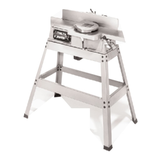
U N PACKING A N D CLEANING The 6 Motorized Jointer is shipped complete in one container. Carefully unpack the jointer, s tand, and all loose items from the container. Figs. 4 and 5 illustrate the items supplied with the jointer. 1 . -
Page 7: A S S E M B Ly Instructions
F i g . 5 2 6 . Legs for St and (4) 2 9 . Top Front and Rear Braces 3 2 . 1 / 2 Long Carriage Bolts f o r f o r St and (25-1/2 long) St and (32) 2 7 . -
Page 8: Assembling St And And Dust Chute To Jointer
ASSEMBLING STA N D A N D D U S T C H U T E TO JOINTER M A K E C E R TAIN T H E MACHINE I S DISCONNECTED F R O M T H E P O W E R S O U R C E A N D T H AT KNIFE G U A R D ( A ) FIG. -
Page 9: Assembling Motor Pulley Guard
ASSEMBLING M O TO R PULLEY G U A R D M A K E C E R TAIN T H E MACHINE I S DISCONNECTED F R O M T H E P O W E R S O U R C E A N D T H AT KNIFE G U A R D ( A ) FIG. -
Page 10: Assembling Cutterhead Guard
5 . Assemble the free end of spring (M) Fig. 16, onto the rear edge of bracket (F). NOTE: The tension on spring (M) Fig. 16, automatically allows safety guard (N) to move forward with the fence (K) and over the rear of the cutter- head for operator safety. -
Page 11: Extension C O R D S
EXTENSION C O R D S TO TA L LENGTH O F G A G E O F EXTENSION C O R D IN FEET C O R D TO U S E Use proper extension cords. Make sure your extension cord is in good condition and is a 3-wire extension cord 0 - 2 5 1 6 AW G... -
Page 12: O P E R Ating C O N T R O L S A N D Adjustments
O P E R ATING C O N T R O L S A N D ADJUSTMENTS ON/OFF SWITCH The on/off s w i t c h ( A ) F i g . 2 3 , i s l o c a t e d a t t h e f r o n t l e ft s i d e o f t h e j o i n t e r. - Page 13 5 . I f t h e k n i f e i s h i g h o r l o w a t e i t h e r e n d , s l i g h t l y t u r n four screws (C) Fig.
-
Page 14: Adjusting Depth-Of-Cut
ADJUSTING DEPTH-OF-CUT The jointer can be set to cut any depth from a very thin shaving to 3/8 . If a cut deeper than 3/8 is desired, the cut should be made in three or more passes. 1 . M A K E C E R TAIN THE MACHINE I S DISCONNECT- E D F R O M THE P O W E R S O U R C E. -
Page 15: Fence Adjustments
Fig. 36 Fig. 37 FENCE ADJUSTMENTS The fence can be easily moved across the table and can t i l t 4 5 d e g r e e s l e ft o r r i g h t a t a n y p o s i t i o n o n t h e ta b l e . 1 . -
Page 16: Jointing An Edge
JOINTING AN EDGE This is the most common operation for the jointer. S e t t h e guide fence square with the table. Depth of cut should be the minimum required to obtain a straight edge. Hold the best face of the piece firmly against the fence throughout the feed as shown in Fig. -
Page 17: Beveling
BEVELING To cut a bevel, lock the fence at the required angle and run the work across the knives while keeping the work firmly against the fence and tables. Several passes may be necessary to arrive at the desired result. When the a n g l e i s s m a l l , t h e r e i s l i t t l e d i fference whether the fence i s t i l t e d t o t h e r i g h t o r l e ft. -
Page 18: Planing Warped Pieces
OR THIN WORK When planing short or thin pieces, always use push blocks to minimize all danger to the hands. Fig. 45, illus- Fig. 45 trates using the Delta 37-108 Push Blocks properly. PERFORM PLANING OPERATIONS ON M ATERIAL SHORTER THAN 10 INCHES, NARROWER THAN 3/4 INCH, WIDER THAN 6 INCHES, OR LESS THAN 1/2 INCH THICK (REFER TO FIG. -
Page 19: Removing, Replacing, And Resetting Knives
REMOVING, REPLACING, A N D RESETTING KNIVES If the knives are removed from the cutterhead for re- placement or regrinding, care must be used in removing, replacing, and resetting them as follows: 1 . DISCONNECT THE MACHINE F R O M THE P O W E R Fig. -
Page 20: Blade Care
9. Lower the infeed table and place a straight edge (J) Fig. 53, on the outf e e d table extending over the cutter- head as shown. 10. Rotate the cutterhead by hand until the knife is at its highest point at each end of the cutterhead. To raise the knife, use wrench (E) Fig. -
Page 21: Constructing A Push Stick
CONSTRUCTING A PUSH STICK Narrow pieces of stock that are close to 10 inch minimum length should be handled with a push stick and push block. F i g . 5 5 , i s a pattern for a push stick. -
Page 22: W A R R A N T Y
Two Year Limited Warranty Delta will repair or replace, at its expense and at its option, any Delta machine, machine pa r t , o r machine accessory which in normal use has proven to be defective in workmanship or material,... - Page 23 Delta Distributor, Authorized · Service Center, or Porter-Cable Delta Factory Service Center. If you do not have access to any of these, call 800-223-7278 and you will · be directed to the nearest Porter-Cable Delta Factory Service Center. Las Estaciones de Servicio Autorizadas están ubicadas en muchas grandes ciudades.