Table of Contents
Advertisement
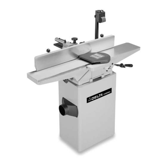
6" Professional Jointer
(Model 37-195)
(Model 37-275X)
PART NO. 909995 - 01-22-03
Copyright © 2003 Delta Machinery
To learn more about DELTA MACHINERY
visit our website at: www.deltamachinery.com.
For Parts, Service, Warranty or other Assistance,
1-800-223-7278 (
1-800-463-3582).
please call
In Canada call
Advertisement
Table of Contents

Related Manuals for Delta 37-195


Summary of Contents for Delta 37-195
- Page 1 6" Professional Jointer (Model 37-195) (Model 37-275X) PART NO. 909995 - 01-22-03 Copyright © 2003 Delta Machinery To learn more about DELTA MACHINERY visit our website at: www.deltamachinery.com. For Parts, Service, Warranty or other Assistance, 1-800-223-7278 ( 1-800-463-3582). please call...
- Page 2 If you have any questions relative to a particular application, DO NOT use the machine until you have first contacted Delta to determine if it can or should be performed on the product.
- Page 3 Replace missing, damaged or failed parts before resuming operation. 24. THE USE of attachments and accessories not recommended by Delta may result in the risk of injuries. 25. ADDITIONAL INFORMATION regarding the safe and proper operation of this product is available from...
-
Page 4: Grounding Instructions
A separate electrical circuit should be used for your machines. This circuit should not be less than #12 wire and should be protected with a 20 Amp time lag fuse. If an extension cord is used, use only 3-wire extension cords which have 3- prong grounding type plugs and matching receptacle which will accept the machine’s plug. -
Page 5: Extension Cords
OPERATING INSTRUCTIONS FOREWORD Delta Model 37-195 is a 6" Professional Jointer with a cutting capacity of 6-1/8" (156mm) width, 1/8" depth (3mm max.) and 1/2" (13mm) rabbeting. Unit includes; heavy-duty 1 hp, 120/240 volt induction motor, stand, dust chute, fence, three- knife cutterhead, cutterhead guard, and push blocks. - Page 6 1. Jointer 2. Fence Carriage Assembly 3. Cutterhead Pulley Guard/Carriage Mounting Bracket 4. Switch Mounting Bracket 5. Cutterhead Guard 6. Fence Tilting Handles (2) 7. Fence 8. Push Blocks (2) JOINTER PARTS Fig. 4 9. 12-14mm Open End Wrench 10. 8-10mm Open End Wrench 11.
- Page 7 16. Stand with Pre-Wired Switch 17. Dust Chute 18. V-Belt 19. Pulley 20. M10x1.5x20mm Hex Socket Head Screw (3) 21. M8x1.25x55mm Hex Socket Head Screw (4) 22. M8x1.25x30mm Hex Socket Head Screw (2) 23. M8x1.25x25mm Hex Socket Head Screw (2) 24.
-
Page 8: Assembling Jointer To Stand
ASSEMBLING JOINTER TO STAND 1. The outfeed end (N) Fig. 9, of the jointer must be pointing toward the end of the stand with dust chute opening (B) Fig. 7. 2. Remove three screws (C) Fig. 7, and loosen two screws (D). - Page 9 ASSEMBLING BELT AND ALIGNING PULLEYS 1. Place belt (A) Fig. 11, in groove of cutterhead pulley (B) and motor pulley (C). 2. Make certain the motor pulley (C) Figs. 11 and 12, is properly aligned with cutterhead pulley (B) by placing a straight edge (D) Fig.
- Page 10 ASSEMBLING FENCE CARRIAGE ASSEMBLY 1. Fasten fence carriage assembly (A) Fig. 15, to cutterhead pulley guard/carriage mounting bracket (C). Align the holes in the fence carriage assembly (A) one of which is shown at (D), with the holes in the pulley guard/carriage mounting bracket (C).
- Page 11 ASSEMBLING CUTTERHEAD GUARD 1. Remove set screw (A) Fig. 20 from cutterhead guard post (F) with the 2.5mm hex wrench. Insert post (F) through hole in the infeed table. NOTE: A spring is supplied in knob assembly (E) that returns the guard (C) over the cutterhead after a cut has been made.
- Page 12 ASSEMBLING DUST CHUTE The jointer stand has a built-in dust chute (A) Fig. 25. If this machine is to be used with a dust collection system, the supplied dust collector connector (B) Fig. 26, can be fastened to jointer stand (C) with four #10-16x1/2" sheet metal screws (D) as shown.
- Page 13 LOCKING SWITCH IN THE “OFF” POSITION IMPORTANT: When the tool is not in use, the switch should be locked in the “OFF” position to prevent unauthorized use. Insert the shank of padlock (C) Fig. 33, through the holes in the switch plate to lock the on/off switch trigger (A).
- Page 14 INFEED TABLE POSITIVE STOPS D I S C O N N E C T M A C H I N E F R O M POWER SOURCE. Positive stops are provided to limit the height and depth of the infeed table. To adjust the stops, loosen two locknuts (F) and (G) Fig.
- Page 15 Fig. 41 5. If the knife is high or low at either end, slightly turn the four screws (D) Fig. 41, in the knife locking bar clockwise to loosen using the wrench (E) supplied. Then adjust the height of the knife by turning the knife raising screws (F) Fig.
- Page 16 ADJUSTING TABLE GIBS “Gibs”’ are provided to take up all play between the mating dovetail ways of the base and the infeed and outfeed tables. The ”gib” for the infeed table is shown at (A) Fig. 46, and the “gib” for the outfeed table is shown at (B) Fig.
- Page 17 ADJUSTING FENCE POSITIVE STOP NOTE: SWITCH HAS BEEN REMOVED FOR CLARITY OF ILLUSTRATIONS ONLY. The fence on this jointer is equipped with positive stops that allow you to rapidly tilt the fence to the 90 and 45 degree angle to the table in the inward or outward position.
- Page 18 REMOVING, REPLACING, AND RESETTING KNIVES If the knives are removed from the cutterhead for re- placement or sharpening, care must be used in removing, replacing, and resetting them. D I S C O N N E C T M A C H I N E F R O M POWER SOURCE.
- Page 19 13. Rotate the cutterhead by hand until the knife is at its highest point at each end of the cutterhead. To raise the knife, use wrench (E) Fig. 58, and turn raising screw clockwise until the knife just touches the straight edge (J) on each end and center of the cutterhead when the knife is at its highest point.
-
Page 20: Taper Cuts
SURFACING Surfacing is identical to the jointing operation except for the position of the workpiece. For surfacing, the major flat surface of the workpiece is placed on the infeed table of the jointer with the narrow edge of the workpiece against the fence, as shown in Fig. -
Page 21: Direction Of Grain
WHEN SURFACING SHORT OR THIN PIECES, ALWAYS USE PUSH BLOCKS TO MINIMIZE ALL DANGER TO THE HANDS. Fig. 66, illustrates using the Delta Push Blocks properly. PERFORM OPERATIONS ON MATERIAL SHORTER THAN 10 INCHES, NARROWER THAN 3/4 INCH, WIDER THAN 6 INCHES, OR LESS THAN 1/2 INCH THICK (REFER TO FIG. - Page 22 CONSTRUCTING A PUSH STICK Narrow pieces of stock that are close to 10 inch minimum length should be handled with a push stick and push block. The Fig. below is a pattern for a push stick.
- Page 23 1-800-223-7278 (In Canada call 1-800-463-3582). Delta will repair or replace, at its expense and at its option, any Delta machine, machine part, or machine accessory which in normal use has proven to be defective in workmanship or material, provided that the customer returns the product prepaid to a Delta factory service center or authorized service station with proof of purchase of the product within two years and provides Delta with reasonable opportunity to verify the alleged defect by inspection.
- Page 24 Delta products should be obtained by contacting any Porter-Cable · Service Center, or Porter-Cable Delta Factory Service Center. If you do not have access to any of these, call 800-223-7278 and you will · be directed to the nearest Porter-Cable Delta Factory Service Center.