Table of Contents
Advertisement
6" Deluxe Jointer
(Model JT360)
PART NO. A05753 - 09-17-024
Copyright © 2004 Delta Machinery
To learn more about DELTA MACHINERY
ESPAÑOL: PÁGINA 29
visit our website at: www.deltamachinery.com.
For Parts, Service, Warranty or other Assistance,
1-800-223-7278 (
1-800-463-3582).
please call
In Canada call
Advertisement
Table of Contents

Related Manuals for Delta JT360


Summary of Contents for Delta JT360
- Page 1 6" Deluxe Jointer (Model JT360) PART NO. A05753 - 09-17-024 Copyright © 2004 Delta Machinery To learn more about DELTA MACHINERY ESPAÑOL: PÁGINA 29 visit our website at: www.deltamachinery.com. For Parts, Service, Warranty or other Assistance, 1-800-223-7278 ( 1-800-463-3582). please call...
-
Page 2: Table Of Contents
NOT be modified and/or used for any application other than for which it was designed. If you have any questions relative to its application DO NOT use the product until you have written Delta Machinery and we have advised you. -
Page 3: Safety Guidelines
SAFETY GUIDELINES - DEFINITIONS It is important for you to read and understand this manual. The information it contains relates to protecting YOUR SAFETY and PREVENTING PROBLEMS. The symbols below are used to help you recognize this information. Indicates an imminently hazardous situation which, if not avoided, will result in death or serious injury. Indicates a potentially hazardous situation which, if not avoided, could result in death or serious injury. -
Page 4: General Safety Rules
MANUAL BEFORE OPERATING THE MACHINE. accessories and attachments not recommended by Learning the machine’s application, limitations, and Delta may cause damage to the machine or injury to the specific hazards will greatly minimize the possibility of user. accidents and injury. -
Page 5: Additional Specific Safety Rules
ADDITIONAL SAFETY RULES FOR JOINTERS FAILURE TO FOLLOW THESE RULES MAY RESULT IN SERIOUS PERSONAL INJURY. HOLD THE WORKPIECE FIRMLY against the table DO NOT OPERATE THIS MACHINE until it is and fence. Loss of control of the workpiece can completely assembled and installed according to the cause kickback and result in serious injury. -
Page 6: Power Connections
POWER CONNECTIONS A separate electrical circuit should be used for your machines. This circuit should not be less than #12 wire and should be protected with a 20 Amp time lag fuse. If an extension cord is used, use only 3-wire extension cords which have 3- prong grounding type plugs and matching receptacle which will accept the machine’s plug. -
Page 7: Functional Description
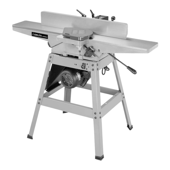
FUNCTIONAL DESCRIPTION FOREWORD Delta ShopMaster Model JT360 is a Deluxe 6" (152mm) Jointer with designed cutting capacity of 6" (152mm) width, 1/2" (13mm) depth and rabbeting 1/2" (13mm). Unit includes; heavy-duty 3/4 hp, 120/240 volt induction motor, stand, dust chute, center-mounted fence, three-knife cutterhead, cutterhead guard, and push blocks. -
Page 8: Carton Contents
CARTON CONTENTS Fig. 4 Fig. 4A Fig. 4B UNPACKING AND CLEANING WARNING: JOINTER WEIGHT IS APPROXIMATELY 175 LBS. CARE MUST BE TAKEN WHEN LIFTING JOINTER ONTO STAND. A MINIMUM OF TWO PEOPLE WILL BE REQUIRED TO LIFT THE MACHINE.Your new jointer is shipped complete in one carton. Carefully unpack the jointer and all loose items. Fig. 4, Fig. 4A and Fig. - Page 9 JOINTER PARTS Fig. 4 Fig. 4A 1. Motor and Switch 25. Dust Collector Adapter 2. Jointer 26. Push Blocks 3. Motor Pulley 27. Infeed Table Adjustment Rod, Handle, and Nut 4. V-Belt 5. Two Top End Braces for Stand (11-3/4") 6.
-
Page 10: Assembly
ASSEMBLY FOR YOUR OWN SAFETY, DO NOT CONNECT THE MACHINE TO THE POWER SOURCE UNTIL THE MACHINE IS COMPLETELY ASSEMBLED AND YOU READ AND UNDERSTAND THE ENTIRE INSTRUCTION MANUAL. ASSEMBLY TOOLS REQUIRED 6mm Allen Wrench 12x14mm Open End Wrench 4mm Allen Wrench 8x10mm Open End Wrench 3mm Allen Wrench (All are supplied.) - Page 11 MOTOR AND SWITCH TO STAND 1. Assemble motor (B) Fig. 7, to the bottom of the dust chute. Align the four holes (F) Fig. 7, in the dust chute, with the four holes in the motor mounting plate. Insert a 5/16-18x1¼"carriage bolt through hole in dust chute and hole in motor mounting plate.
- Page 12 3. Using the supplied wrench (or a 14 mm socket wrench), fasten the jointer to the top of stand using the three M10.2 lockwashers and special studs. Two of the special studs are shown at (D) Fig. 10, for the infeed end of the machine, and one special stud is shown at (D) Fig.
- Page 13 INFEED TABLE ADJUSTMENT HANDLE 1. Turn locknut (C) Fig. 12, clockwise on infeed table adjustment handle (B) as far as it will go. 2. Thread handle (B) Fig. 12, into block (D) which is located below infeed table (E). 3. Turn locknut (C) Fig. 13 clockwise to tighten against block (D).
- Page 14 MOTOR PULLEY Assemble motor pulley (A) Fig. 16, to motor shaft with the hub of the pulley in the outer position as shown. Make sure key (B) is inserted in the keyway of the motor pulley and shaft. BELT, ALIGNING PULLEYS, AND Fig.
- Page 15 MOTOR PULLEY AND BELT GUARD Assemble the motor pulley and belt guard (A) Fig. 19, to the jointer base using the four M6x1x10mm cheese head screws, two of which are shown at (B), and four M6.1 lockwashers. MAKE CERTAIN MOTOR PULLEY IS NOT CONTACTING GUARD.
-
Page 16: Operation
CUTTERHEAD GUARD 1. Remove set screw (A) Fig. 23, from post (B) of cutterhead guard (C). 2. Assemble cutterhead guard (C) Fig. 23, to the jointer by inserting post (B) down through the hole in the infeed table. NOTE: A spring is supplied in knob assembly (D) that returns the guard (C) over the cutterhead after a cut has been made. - Page 17 INFEED TABLE ADJUSTMENTS 1. To raise or lower the infeed table, loosen table lockhandle (A) Fig. 35, move the table raising and lowering handle (B) up or down until the table is at the desired position and tighten table lockhandle (A). 2.
- Page 18 KNIFE AND OUTFEED TABLE ADJUSTMENTS In order to do accurate work, the knives must be exactly level with the outfeed table. To check and adjust, proceed as follows: 1. DISCONNECT MACHINE FROM POWER SOURCE. 2. Loosen lock lever (A) Fig. 39, and lower the infeed table by pushing handle (B) down.
- Page 19 ADJUSTING TABLE GIBS “Gibs” are provided to take up all play between the mating dovetail ways of the base and the infeed and outfeed tables. The “gib” for the infeed table is shown at (A) Fig. 46, and the “gib” for the outfeed table is shown at (B) Fig. 47. Proper “gib”...
- Page 20 ADJUSTING FENCE POSITIVE STOPS The fence on this jointer is equipped with positive stops that allow you to rapidly tilt the fence to the 90 and 45 degree angle to the table in the inward or outward position. To check and adjust the positive stops, proceed as follows: 1.
- Page 21 Fig. 55 Fig. 56 ADJUSTING FENCE GUARDS Two guards, one of which is shown at (A) Fig. 55, are provided on each side of the fence bracket to close up the opening between the fence bracket (B) and the fence (C) limiting access to the cutterhead. When the fence is tilted, the guard (A) Fig.
- Page 22 Mating surfaces of cutterhead to blade 9. The knives are adjusted correctly when the cutting and blade to bar to be tight and parallel edge of the knife extends out .060" (1.5 mm) from the cutterhead diameter. Face of screw and face of cutterhead to be parallel 10.
- Page 23 DEFINITIONS OF JOINTING AND PLANING OPERATIONS Fig. 62 Fig. 63 1. JOINTING OPERATIONS – Jointing cuts or edge 2. PLANING OPERATIONS – Planing or surfacing are jointing are made to square an edge of a workpiece. The identical to the jointing operation except for the position workpiece is positioned on the jointer with the narrow of the workpiece.
-
Page 24: Taper Cuts
PLANING OR SURFACING Planing or surfacing is identical to the jointing operation except for the position of the workpiece. For planing, the major flat surface of the workpiece is placed on the infeed table of the jointer with the narrow edge of the workpiece against the fence, a shown in Fig. -
Page 25: Troubleshooting
CORRECT FEED - WITH THE GRAIN Fig. 72 Fig. 73 TROUBLESHOOTING For assistance with your machine, visit our website at www.deltamachinery.com for a list of service centers or call the DELTA Machinery help line at 1-800-223-7278 (In Canada call 1-800-463-3582). -
Page 26: Maintenance
MAINTENANCE After considerable use, the knives will become dull and it will not be possible to do accurate work. Unless badly damaged by running into metal or other hard material, the knives may be sharpened as follows: WHETTING KNIVES DISCONNECT MACHINE FROM OILSTONE PARTLY... -
Page 27: Service
Two Year Limited New Product Warranty Delta will repair or replace, at its expense and at its option, any new Delta machine, machine part, or machine accessory which in normal use has proven to be defective in workmanship or material, provided that the customer returns the product prepaid to a Delta factory service center or authorized service station with proof of purchase of the product within two years and provides Delta with reasonable opportunity to verify the alleged defect by inspection. - Page 28 NOTES...
-
Page 29: Español
Phone: (514) 336-8772 Fax: (604) 420-3522 Fax: (514) 336-3505 The following are trademarks of PORTER-CABLE • DELTA (Las siguientes son marcas registradas de PORTER-CABLE • DELTA S.A.) (Les marques suivantes sont des marques de fabriquant de la PORTER-CABLE • DELTA): Auto-Set ®...