Advertisement
Table of Contents
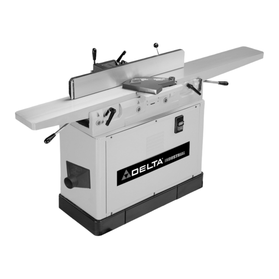
DJ-20
8" Jointer
(Model 37-365X, 37-680 and 37-680X)
PART NO. A06586 - 08-23-04
Copyright © 2004 Delta Machinery
To learn more about DELTA MACHINERY
visit our website at: www.deltamachinery.com.
For Parts, Service, Warranty or other Assistance,
1-800-223-7278 (
1-800-463-3582).
please call
In Canada call
Advertisement
Table of Contents

Related Manuals for Delta DJ-20 Series


Summary of Contents for Delta DJ-20 Series
- Page 1 DJ-20 8" Jointer (Model 37-365X, 37-680 and 37-680X) PART NO. A06586 - 08-23-04 Copyright © 2004 Delta Machinery To learn more about DELTA MACHINERY visit our website at: www.deltamachinery.com. For Parts, Service, Warranty or other Assistance, 1-800-223-7278 ( 1-800-463-3582). please call...
-
Page 2: Table Of Contents
NOT be modified and/or used for any application other than for which it was designed. If you have any questions relative to its application DO NOT use the product until you have written Delta Machinery and we have advised you. -
Page 3: Safety Guidelines
SAFETY GUIDELINES - DEFINITIONS It is important for you to read and understand this manual. The information it contains relates to protecting YOUR SAFETY and PREVENTING PROBLEMS. The symbols below are used to help you recognize this information. Indicates an imminently hazardous situation which, if not avoided, will result in death or serious injury. Indicates a potentially hazardous situation which, if not avoided, could result in death or serious injury. -
Page 4: General Safety Rules
2. WEAR EYE PROTECTION. ALWAYS USE SAFETY accessories and attachments not recommended by GLASSES. Also use face or dust mask if cutting Delta may cause damage to the machine or injury to the operation is dusty. Everyday eyeglasses are NOT safety user. -
Page 5: Additional Specific Safety Rules
ADDITIONAL SAFETY RULES FOR JOINTERS FAILURE TO FOLLOW THESE RULES MAY RESULT IN SERIOUS INJURY. HOLD THE WORKPIECE FIRMLY against the table DO NOT OPERATE THIS MACHINE until it is and fence. Loss of control of the workpiece can completely assembled and installed according to the cause kickback and result in serious injury. - Page 6 POWER CONNECTIONS A separate electrical circuit should be used for your machines. This circuit should not be less than #12 wire and should be protected with a 20 Amp time lag fuse. If an extension cord is used, use only 3-wire extension cords which have 3- prong grounding type plugs and matching receptacle which will accept the machine’s plug.
-
Page 7: Functional Description
FUNCTIONAL DESCRIPTION FOREWORD Delta Model 37-365X, 37-680 and 37-680X are 8" precision jointers with a cutting capacity of 8" (203mm) width, 5/8" depth (16mm max.) and 5/8" (16mm) rabbeting. Unit includes; heavy-duty 1-1/2 hp, 120/240 volt motor, fence, three-knife cutterhead, cutterhead guard, and push blocks. -
Page 8: Carton Contents
CARTON CONTENTS Fig. 2 1. Jointer 7. Fence Tilting Handle 2. Rabbeting Ledge 8. 10x13mm Open End Wrench 3. Motor Pulley 9. 4mm Hex Wrench 4. Fence 10. 2.5mm Hex Wrench 5. Cutterhead Guard 11. M8x1.25x25mm Socket Head Screw (8) 6. -
Page 9: Assembly
Fig. 3 1. Stand, Motor, and Electricals 6. 1/4" Flat Washer (2) 2. Belt 7. 1/4-20 Hex Nut (2) 3. Cutterhead Pulley/Belt Guard 8. #10-16x1/2” Hex Head Screw (4) 4. Push Blocks (2) 9. Dust chute 5. 1/4-20x5/8" Hex Head Screw (2) ASSEMBLY ASSEMBLY TOOLS REQUIRED * 4mm hex head wrench (supplied) - Page 10 THE JOINTER IS EXTREMELY HEAVY. HAVE TWO OR MORE PEOPLE HELP LIFT AND MOVE MACHINE AROUND DURING ASSEMBLY. JOINTER TO STAND NOTE: THE MOTOR IS BOLTED TO THE TOP OF THE STAND AND MUST BE ATTACHED TO THE MOTOR MOUNTING BRACKETS. 1.
- Page 11 ASSEMBLING MOTOR PULLEY Assemble motor pulley (K) Fig. 7A, to motor shaft with the hub of the pulley in the outer position as shown. Make certain key (L) is inserted in the keyway of the pulley and motor shaft, then tighten set screw (M) using the 2.5 mm hex wrench (not shown).
- Page 12 ASSEMBLING FENCE CARRIAGE ASSEMBLY 1. Remove the two M10x1.5x30mm hex socket head screws (A) Fig. 11, and 10mm flat washers from the back of the jointer base at location (C). 2. Align the two holes (B) Fig. 11, in the fence carriage assembly, with the two tapped holes (C) in the back of the jointer base.
- Page 13 ASSEMBLING RABBETING LEDGE 1. Remove the two M6x1x20mm socket head screws (C) Fig. 15 from hole location (B) in the front of the Jointer. 2. Align the two holes (A) Fig. 15, in the rabbeting ledge, with the two holes (B) in the front of the Jointer.
-
Page 14: Operation
OPERATION OPERATIONAL CONTROLS AND ADJUSTMENTS STARTING AND STOPPING JOINTER To turn the machine “ON”, push the green start button (A) Fig. 17. To turn the machine “OFF”, push the red stop button (B). Fig. 17 LOCKING SWITCH IN THE “OFF” POSITION IMPORTANT: When the tool is not in use, the switch should be locked in the “OFF”... - Page 15 INFEED TABLE ADJUSTMENTS To raise or lower the infeed table (see Fig. 4A), loosen table lock handle (A) Fig. 19, and move the table raising and lowering hand lever (B) up or down until the table is at the desired position and tighten table lock handle (A). NOTE: The table lock handle (A) can be repositioned by pulling out the handle and repositioning it on the serrated nut located underneath the handle.
- Page 16 KNIFE ADJUSTMENTS In order to do accurate work, the knives must be exactly level with the outfeed table. To check and adjust, proceed as follows: D I S C O N N E C T M A C H I N E F R O M POWER SOURCE.
- Page 17 FENCE OPERATION The fence can be moved across the table by loosening lock lever (A) Fig. 30, move the fence to the desired position, and tighten lock lever (A) securely. As the fence is moved across the table, the sliding portion of the fence bracket (F) guards the cutterhead in back of the fence as shown.
- Page 18 2. Using a square (D) Fig. 34, check to see if the fence is at 90 degrees to the table, as shown. 3. If the fence is not at 90 degrees to the table, loosen set screw (E) in the index collar (B), Fig. 33, and loosen the fence locking handle (C).
- Page 19 CUTTERHEAD ROTATION The rotation of the cutterhead must be in a clockwise direction when viewed from the left side of the machine; that is, the knives must be rotating toward the infeed table from the top. If the cutterhead rotation is incorrect, disconnect the machine from the power source and proceed as follows: Single Phase Machines –...
- Page 20 JOINTING AN EDGE This is the most common operation for the jointer, these cuts are made to square an edge of a workpiece. Set the guide fence square with the table. Depth of cut should be the minimum required to obtain a straight edge. Hold the best face of the piece firmly against the fence throughout the feed as shown in Fig.
- Page 21 WHEN SURFACING SHORT OR THIN DIMENSIONS PIECES, ALWAYS USE PUSH BLOCKS TO MINIMIZE ALL DANGER TO THE HANDS. Fig. 44, illustrates using the Delta Push Blocks properly. PERFORM SURFACING OPERATIONS ON MATERIAL SHORTER THAN 10 INCHES, NARROWER THAN 3/4 INCH, WIDER THAN 8 INCHES, OR LESS THAN 1/2 INCH THICK (REFER TO FIG.
-
Page 22: Troubleshooting
Fig. 46 Fig. 47 TROUBLESHOOTING For assistance with your tool, visit our website at www.deltamachinery.com for a list of service centers or call the DELTA Machniery help line at 1-800-223-7278 (In Canada call 1-800-463-3582). MAINTENANCE KEEP MACHINE CLEAN LUBRICATION Periodically blow out all air passages with dry compressed... - Page 23 REMOVING, REPLACING, AND RESETTING KNIVES If the knives are removed from the cutterhead for re- placement or sharpening, care must be used in removing, replacing, and resetting them. D I S C O N N E C T M A C H I N E F R O M POWER SOURCE.
- Page 24 12. Lower the infeed table and place a straight edge (J) Fig. 53, on the outfeed table extending over the cutterhead as shown. 13. Rotate the cutterhead by hand until the knife is at its highest point at each end of the cutterhead. To raise the knife, use wrench (E) Fig.
- Page 25 CONSTRUCTING A PUSH STICK Narrow pieces of stock that are close to 10 inch minimum length should be handled with a push stick and push block. The diagram below is a pattern for a push stick.
- Page 26 NOTES...
-
Page 27: Service
Two Year Limited New Product Warranty Delta will repair or replace, at its expense and at its option, any new Delta machine, machine part, or machine accessory which in normal use has proven to be defective in workmanship or material, provided that the customer returns the product prepaid to a Delta factory service center or authorized service station with proof of purchase of the product within two years and provides Delta with reasonable opportunity to verify the alleged defect by inspection. - Page 28 Fax: (519) 767-4131 Fax: (604) 420-3522 Fax: (514) 336-3505 The following are trademarks of PORTER-CABLE • DELTA (Las siguientes son marcas registradas de PORTER-CABLE • DELTA S.A.) (Les marques suivantes sont des marques de fabriquant de la PORTER-CABLE • DELTA): Auto-Set ®...