Table of Contents
Advertisement
Specifications
lGeneral
Power Source:
Power consumption:
Dimensions (W×H×D):
Mass:
lAmplifier section
RMS Output Power: Dolby Digital Mode
lTotal RMS Dolby Digital
mode Power:
At 1kHz and total harmonic of 10%
lFront:
lCenter:
lSurround:
At 100Hz and total harmonic of 10%
lActive subwoofers:
FTC Output Power: Dolby Digital Mode
lTotal FTC Dolby Digital mode Power:
At 120Hz-20kHz and total harmonic of 1%
lFront:
lCenter:
lSurround:
AC 120V, 60Hz
85 W
430×70×439.2 mm
(16-15/16"×2-3/4"×17-19/64")
4.65 kg (10.25Ibs)
850 W
110 W/ Channel (3Ω)
225 W/ Channel (6Ω)
90 W/ Channel (4Ω)
225 W/ Channel (6Ω)
300 W
40 W/ Channel (3Ω)
75 W/ Channel (6Ω)
40 W/ Channel (4Ω)
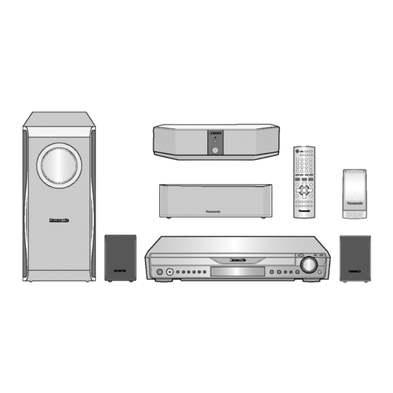
DVD Home Theater Sound System
SA-HT640WP
SA-HT640WPC
Colour
(S).......................Silver Type
At 45Hz-120Hz and total harmonic of 1%
lSubwoofer:
lFM tuner section
Preset Memory::
Frequency Range:
Sensitivity:
S/N 26dB
Antenna Terminals:
lAM tuner section (AM/MW)
Frequency Range:
AM Sensitivity S/N 20dB at
1000kHz:
lPhone Jack:
Terminal:
lFront/Rear M. Port:
Sensitivity:
Terminal (Input):
lDisc section
Discs played [8 cm (3") or 12 cm (5")]:
© 2006 Panasonic AVC Networks Singapore Pte.
Ltd. All rights reserved. Unauthorized copying and
distribution is a violation of law.
ORDER NO.MD0512492C1
A6
65 W/ Channel (6Ω)
FM 15 stations
AM/MW 15 stations
87.9-107.9MHz
(200kHz in step)
87.5-108.0MHz
(100kHz in step)
2.5µV (IHF)
2.2µV
75Ω (unbalanced)
520-1710kHz (10kHz in step)
560µV/m
Stereo 3.5 mm (1/8") jack
100mV (4.7kΩ)
Stereo 3.5 mm (1/8") jack
Advertisement
Table of Contents
Troubleshooting

Related Manuals for Panasonic SA-HT640WP


Summary of Contents for Panasonic SA-HT640WP
-
Page 1: Specifications
75 W/ Channel (6Ω) lDisc section lSurround: 40 W/ Channel (4Ω) Discs played [8 cm (3”) or 12 cm (5”)]: © 2006 Panasonic AVC Networks Singapore Pte. Ltd. All rights reserved. Unauthorized copying and distribution is a violation of law. - Page 2 SA-HT640WP / SA-HT640WPC 0.7 Vp-p (75 Ω) (1) DVD [DVD-Video, DVD-Audio] output level: 0.7 Vp-p (75 Ω) (2) DVD-RAM [DVD-VR, JPEG(*4,5)] output level: (3) DVD-R [DVD-Video] Terminal: Pin jack (Y: green, P : blue, : red) (1 system) (4) DVD-RW [DVD-Video]...
-
Page 3: Table Of Contents
SA-HT640WP / SA-HT640WPC CONTENTS Page Page 1 Safety Precautions 12 Service Positions 1.1. GENERAL GUIDELINES 12.1. Checking & Repair Main P.C.B., Power P.C.B., FL and 1.2. Before Repair and Adjustment Head phone P.C.B. 1.3. Protection Circuitry 12.2. Checking & Repair DVD Module P.C.B... - Page 4 SA-HT640WP / SA-HT640WPC 23 Explode Views 24 Replacement Parts List 23.1. Cabinet Parts Location 24.1. Component Parts List 23.2. Packaging...
-
Page 5: Safety Precautions
SA-HT640WP / SA-HT640WPC 1 Safety Precautions 1.1. GENERAL GUIDELINES 1. When servicing, observe the original lead dress. If a short circuit is found, replace all parts which have been overheated or damaged by the short circuit. 2. After servicing, see to it that all the protective devices such as insulation barriers, insulation papers shields are properly installed. -
Page 6: Protection Circuitry
SA-HT640WP / SA-HT640WPC 1.2.1. Caution for fuse replacement 1.3. Protection Circuitry The protection circuitry may have operated if either of the following conditions are noticed: · No sound is heard when the power is turned on. · Sound stops during a performance. - Page 7 SA-HT640WP / SA-HT640WPC...
-
Page 8: Precaution Of Laser Diode
SA-HT640WP / SA-HT640WPC 3 Precaution of Laser Diode CAUTION: This unit utilizes a class 1 laser. Invisible laser radiation is emitted from the optical pickup lens. Wavelength: 662nm(DVD)/785nm(CD). Maximum output radiation power from pickup: 100µW/VDE When the unit is turned on: 1. -
Page 9: Handling Precautions For Traverse Unit
SA-HT640WP / SA-HT640WPC 5 Handling Precautions for Traverse Unit The laser diode in the optical pickup unit may break down due to static electricity of clothes or human body. Special care must be taken avoid caution to electrostatic breakdown when servicing and handling the laser diode. - Page 10 SA-HT640WP / SA-HT640WPC...
-
Page 11: Accessories
SA-HT640WP / SA-HT640WPC 6 Accessories AC cord Remote control Digital transceiver* AM loop antenna FM indoor antenna Speaker label Video Cable... -
Page 12: Operation Procedures
SA-HT640WP / SA-HT640WPC 7 Operation Procedures 7.1. Operating instructions 7.1.1. Remote Control Key Buttons Operations Television operations Adjust the television volume Turn the unit on/off Select the source DVD/CD, FM/AM, AUX/FRONT Change the television's video input mode MUSIC P./REAR MUSIC P. - Page 13 SA-HT640WP / SA-HT640WPC 7.1.2. Main Unit Key Buttons Operations (SA-HT640W) Standby/on switch [POWER Press to switch the unit from on to standby mode OPEN/CLOSE or vice versa. In standby mode, the unit is still consuming a small amount of power.
- Page 14 SA-HT640WP / SA-HT640WPC 7.1.3. Wireless Surround Speaker Key Buttons Operations (SB-SA640) Wireless selector [WIRELESS ON, OFF] :Select when enjoying audio from the main unit. Power indicator :Select when enjoying audio from MUSIC PORT This indicator lights when the unit is on the surround speaker.
-
Page 15: Disc Information
Recorded with devices using Version 1.1 of the Video Recording Format (a unified video recording standard), such as DVD video recorders, DVD video cameras, personal computers, etc. JPEG Recorded with Panasonic SD multi cameras or DVD video recorders using the DCF (Design rule for Camera File System) Standard Version 1.0. DVD-R... - Page 16 SA-HT640WP / SA-HT640WPC...
-
Page 17: New Features
SA-HT640WP / SA-HT640WPC 8 New Features · This model is equipped with the digital transmitter and receiver (SB-SA640) to enjoy surround sound wirelessly. For more information on this model, please refer to the original service manual. 8.1. RF Wireless Audio Transceiver 8.1.1. - Page 18 SA-HT640WP / SA-HT640WPC · Low power consumption · SNR (for left / right channel analog interface) : 80 dB · THD : 0.2% · Compact : 40mm x 80mm...
-
Page 19: Detail Block Diagram (Receiver Module)
SA-HT640WP / SA-HT640WPC 8.2. Detail Block Diagram (Receiver module) - Page 20 SA-HT640WP / SA-HT640WPC 8.2.1. Operation RF signal transmission and reception: During the receive process, the radio signal is taken from a pair of balanced RF I/O pins that feed into the low noise amplifier (LNA). Direct I/Q down conversion and on-chip filtering send the processed I/Q data to the analog-to-digital converter before processing by the GFSK (Gaussian Frequency Shift Keying) demodulator.
- Page 21 SA-HT640WP / SA-HT640WPC Does the system support any mode to save power consumption? Yes, it has POWER SAVING SCAN mode. When the communication link is lost, the slave starts scanning procedure to re-establish the link. If the slave cannot find the master within a certain amount of time (info stored in EEPROM), the slave automatically goes into power saving scan mode.
- Page 22 SA-HT640WP / SA-HT640WPC How can Master or Slave setting be selected? By software or hardware? It can be selected by external control pin. How long does it take to transmit single packet? To establish communication channel properly, hopping frequency and Syncword of each packet should be determined by Device ID(Identification).
-
Page 23: Class-D Amplifier
SA-HT640WP / SA-HT640WPC 8.3. Class-D Amplifier 8.3.1. How are digital amplifiers different? A digital amplifier incorporates a switching output stage that operates according to a principle known as pulse width modulation (PWM). In contrast to the low-frequency control signal used in a conventional analog amplifier output stage, the switching output stage of a digital amplifier is controlled by a high-frequency digital signal. - Page 24 SA-HT640WP / SA-HT640WPC 8.3.5. What are the potential problems of a Class-D amplifier based system? The two most common issues of class-D amp system are AM interference and EMI. The switching frequency of class-D ranges from 300kHz to 450kHz typically 315kHz. The harmonics of such switching frequency will fall into the AM band of 600kHz to 1710kHz.
- Page 25 SA-HT640WP / SA-HT640WPC Class-D amp systems are basically switching systems. As such, it is prone to EMI. EMI issues can be rectified through proper grounding techniques and proper components layout. It is quite common to see ferrite beads, capacitors and inductors on these systems.
- Page 26 SA-HT640WP / SA-HT640WPC Block diagram: IC Package Information Soldering Information Wave Soldering/Dipping: The maximum permissible temperature of the solder is 260 ーC; solder at this temperature must not be in contact with the joints for more than 5 seconds. The total contact time of successive solder waves must not exceed 5 seconds.
-
Page 27: Self-Diagnosis And Special Mode Setting
SA-HT640WP / SA-HT640WPC 9 Self-Diagnosis and special mode setting 9.1. Service Mode Summary Table The service modes can be activated by pressing various button combination on the player and remote control unit. Below is the summary of major checking: Player buttons... - Page 28 SA-HT640WP / SA-HT640WPC Item Key Operation FL Display Mode Name Description Front Key Jitter check Jitter check In STOP (no disc) mode, Jitter rate is measured and displayed. press STOP button on the Measurement is repeatedly done in player, and "5" button on the cycle of one second.
- Page 29 SA-HT640WP / SA-HT640WPC Item Key Operation FL Display Mode Name Description Front Key Micro-processor firmware version Micro-processor In STOP (no disc) firmware version display & EEPROM checksum display. mode, press STOP button display & on the player, and "7" EEPROM...
- Page 30 SA-HT640WP / SA-HT640WPC Item Key Operation FL Display Mode Name Description Front Key In STOP (no disc) Timer 1 check Timer 1 check mode, press STOP button Laser operation timer Operation time is on the player, and " " measured separately for DVD laser button on the remote and CD laser.
- Page 31 SA-HT640WP / SA-HT640WPC...
-
Page 32: Dvd Self Diagnostic Function-Error Code
SA-HT640WP / SA-HT640WPC 9.3. DVD Self Diagnostic Function-Error Code Error Diagnosis Contents Description of error Automatic FL Display Remarks Code Focus servo error Focus coil NG (OPU unit abnormal) Press [ n STOP] on main unit for next error. Tray loading error /... - Page 33 SA-HT640WP / SA-HT640WPC Error Diagnosis Contents Description of error Automatic FL Display Remarks Code F600 Access failure to Operation stopped because navigation Press [ n STOP] on main management information data is not accessible caused by the unit for next error...
-
Page 34: Sales Demonstration Lock Function
SA-HT640WP / SA-HT640WPC Error Diagnosis Contents Description of error Automatic FL Display Remarks Code F893 FLASH ROM IC problem FLASH ROM IC installed is not operating Press [ n STOP] on main properly (Neccessary replacement of unit for next error... -
Page 35: Service Precautions
SA-HT640WP / SA-HT640WPC power cable from power outlet does not cancel the lock.) 9.5. Service Precautions 9.5.1. Recovery after the DVD player is repaired · When the FLASH ROM IC or HDMI module P.C.B. is replaced, carry out the recovery processing to optimize the drive. -
Page 36: Assembling And Disassembling
SA-HT640WP / SA-HT640WPC 10 Assembling and Disassembling “ATTENTION SERVICER” Be careful when disassembling and servicing. Some chassis components may have sharp edges. Special Note: 1. This section describes the disassembly procedures for all the major printed circuit boards and main components. -
Page 37: Disassembly Flow Chart
SA-HT640WP / SA-HT640WPC 10.1. Disassembly Flow Chart 10.2. Main Components and P.C.B. Locations... -
Page 38: Disassembling The Top Cabinet
SA-HT640WP / SA-HT640WPC 10.3. Disassembling the Top Cabinet Step 1 Remove 7 screws. Step 2 Remove the top cabinet in the direction of arrow. Step 5 Detach the FFC cables from connectors (CN5705, 10.4. Disassembling the Front Panel CN5707 & CN2013). -
Page 39: Disassembling The Rear Panel
SA-HT640WP / SA-HT640WPC Step 4 Remove the mechanism base block. 10.8. Disassembling the FL & Head phone P.C.B. 10.6. Disassembling the Rear Panel · Follow (Step 1) to (Step 7) Item 10.4. · Follow (Step 1) to (Step 2) of Item 10.3. -
Page 40: Disassembling The Ac Inlet, Power & Sub Power P.c.b
SA-HT640WP / SA-HT640WPC Note: Refer to the diagrams of Power P.C.B. (Section 19.3) for location of the parts. 10.10. Disassembling the AC Inlet, 10.12. Disassembly of Regulator IC Power & Sub power P.C.B · Follow (Step 1) to (Step 7) of Item 10.10. -
Page 41: Disassembly Of The Tray Base Guide (L) And Tray Base Guide (R)
SA-HT640WP / SA-HT640WPC Note: Refer to the diagrams of Power P.C.B. (Section 19.3) for location of the parts. Step 1 Remove tray screw and tray spring. Caution: Be careful when removing the Switch Regulator Step 2 Remove rotary tray. IC which has high temperature after prolonged use. -
Page 42: Disassembly Of The Traverse Unit
SA-HT640WP / SA-HT640WPC Step 2 Flip the base mecha unit in vertical position. Step 2 Hook close lock spring to claw (a). Step 3 Rotate close lock gear to direction of arrow, press claw (b) and pull out close lock gear. - Page 43 SA-HT640WP / SA-HT640WPC Step 2 Remove Drive Gear (A) and Drive Gear (B). Step 3 Release the 2 claws in the direction of arrow (1), and then push the pulley pin in the direction of arrow (2). 10.16.2. Disassembly of the Loading Motor P.C.B.
-
Page 44: Assembly Of Tray Assembly
SA-HT640WP / SA-HT640WPC Step 2 Remove 1 screw and support piece. 10.17. Assembly of Tray Assembly Step 1 Rotate cam gear anti-clockwise. Align at position (C) as marking on gear with arrow. 10.16.6. Disassembly of the Slide Plate (L) & (R) and Change Lever Step 1 Press the claw and push the Slide Plate (L) up. - Page 45 SA-HT640WP / SA-HT640WPC Step 3 Push tray assembly to the direction of arrow shown.
-
Page 46: Service Fixture And Tools
SA-HT640WP / SA-HT640WPC 11 Service Fixture and Tools Prepare service tools before proccess service position. Service Tools Loading Motor P.C.B. - Main REEX0633 (11 pin) P.C.B. Sensor P.C.B. - Power P.C.B. REEX0465 (11 pin) 12 Service Positions 12.1. Checking & Repair Main 12.2. -
Page 47: Measurements And Adjustments
SA-HT640WP / SA-HT640WPC 13 Measurements and Adjustments 13.1. Service Tools and Equipment Application Name Number Tilt adjustment DVD test disc DVDT-S20 [SPG] TORX screw driver (T6) Available on sales route. (T6) or RFKZ0185 [SPG] Others Grease RFKXPG641 [SPG] Confirmation CD test disc... -
Page 48: Optical Adjustment
SA-HT640WP / SA-HT640WPC 13.4. Optical adjustment 13.4.1. Optical pickup tilt adjustment Measurement point Adjustment point Mode Disc Tangential adjustment screw T01 (inner periphery) play DVDT-S20 [SPG] Tilt adjustment screw T30 (center periphery) T43 (outer periphery) play Measuring equipment Adjustment value None (Main unit display for servicing is used.) -
Page 49: Abbreviations
SA-HT640WP / SA-HT640WPC 13.5. Abbreviations INITIAL/LOGO ABBREVIATIONS INITIAL/LOGO ABBREVIATIONS A0~UP ADDRESS ERROR TORQUE CONTROL ACLK AUDIO CLOCK ERROR TORQUE CONTROL AD0~UP ADDRESS BUS REFERENCE ADATA AUDIO PES PACKET DATA ENCSEL ENCODER SELECT ADDRESS LATCH ENABLE ETMCLK EXTERNAL M CLOCK (81MHz/40.5MHz) - Page 50 SA-HT640WP / SA-HT640WPC INITIAL/LOGO ABBREVIATIONS INITIAL/LOGO ABBREVIATIONS READ ENABLE VBLANK V BLANKING RFENV RF ENVELOPE COLLECTOR POWER SUPPLY RF PHASE DIFFERENCE OUTPUT VOLTAGE (CD-ROM) REGISTER SELECT VCDCONT VIDEO CD CONTROL (TRACKING RSEL RF POLARITY SELECT BALANCE) RESET DRAIN POWER SUPPLY VOLTAGE...
-
Page 51: Voltage And Waveform Chart
SA-HT640WP / SA-HT640WPC 14 Voltage and Waveform Chart 14.1. DVD Module P.C.B. IC8001 Re f No. MODE CD P LAY IC8001 Re f No. MODE CD P LAY IC8001 Re f No. MODE CD P LAY Re f No. IC8001... -
Page 52: Main P.c.b
SA-HT640WP / SA-HT640WPC 14.2. Main P.C.B. IC2001 Re f No. MODE CD P LAY S TANDBY IC2001 Re f No. MODE CD P LAY S TANDBY IC2001 Re f No. MODE CD P LAY S TANDBY Re f No. IC2001... -
Page 53: Power P.c.b
SA-HT640WP / SA-HT640WPC 14.3. Power P.C.B. Re f No. IC5000 MODE CD P LAY -0.1 -0.1 28.9 -0.1 -29.2 -20.8 29.2 -3.3 -29.5 -17.0 -29.5 -3.3 29.2 29.2 -29.2 -0.1 28.9 S TANDBY -0.1 -0.1 28.9 -29.2 -20.9 29.3 -3.2 -29.4... -
Page 54: Loading Motor P.c.b., Tray Motor P.c.b., Sensor P.c.b
SA-HT640WP / SA-HT640WPC 14.5. Loading Motor P.C.B., Tray Motor P.C.B., Sensor P.C.B. Loading Motor P.C.B. Q9001 Re f No. MODE CD P LAY S TANDBY Tray Motor P.C.B. Q9101 Q9102 Re f No. MODE CD P LAY S TANDBY -0.2 Sensor P.C.B. -
Page 55: Waveform Chart
SA-HT640WP / SA-HT640WPC 14.6. Waveform Chart WF No. IC2001-12 (PLAY) WF No. IC2102-15 (PLAY) WF No. IC2102-17 (PLAY) WF No. IC2102-30 (PLAY) 5.6Vp-p(100nsec/div) 2.5Vp-p(200usec/div) 3.5Vp-p(200usec/div) 12Vp-p(5msec/div) WF No. IC2103-1 (PLAY) WF No. IC2801-11 (PLAY) WF No. IC2801-4 (PLAY) WF No. IC2801-8 (PLAY) 3.4Vp-p(200usec/div) -
Page 56: Illustration Of Ic's, Transistors And Diodes
SA-HT640WP / SA-HT640WPC 15 Illustration of IC's, Transistors and Diodes RFKWMH82H160 C0HBB0000057 (44p) C0ABCB000088 (14p) C3ABPG000133 (54p) C1AB00002463 (100p) C0CBCBD00018 (8p) C3EBEG000073 (8p) MN101C49GHG (100p) C3EBGC000044 (8p) C0FBBK000050 (28p) C9ZB00000461 (132p) MN2DS0003APH (256p) C0JBAB000011 (14p) No.1 C0JBAR000326 (16p) MN864701 (164p) No.1... -
Page 57: Wiring Connection Diagram
SA-HT640WP / SA-HT640WPC 16 Wiring Connection Diagram TO FAN JK6802 TO FAN UNIT UNIT H6901 FL P.C.B. 1 2 3 CN6902 CN5714 RED BLK MUSIC PORT CN5711 1 2 3 CN5704 CN5706 VOLUME VR6800 P5701 POWER P.C.B. JK6801 JK5400 CN6901 AC-INLET P.C.B. - Page 58 SA-HT640WP / SA-HT640WPC...
-
Page 59: Block Diagram
SA-HT640WP / SA-HT640WPC 17 Block Diagram IC8001 IC8251 MN2DS0003APH C0GBG0000048 OPTICAL PICK UP UNIT DV2.1 LSI TRACKING COIL/FOCUS COIL/TRAVERSE/SPINDLE MOTOR DRIVE PHOTO DETECTOR VIN1 VOL4+ VIN2 TRAVERSE VIN3 HEAD MOTOR VIN4 LEVEL VOL4- SHIFT VIN8 BIAS1 VIN7 VHALF VIN6 OPIN+... - Page 60 SA-HT640WP / SA-HT640WPC IC8051 IC8001 IC8421 C3ABPG000133 MN2DS0003APH C0FBBK000050 64M SDRAM DV2.1 LSI AUDIO DAC OUTPUT AMP AND V OUT7 DVD MIX L LOW-PASS FILTER SRCK LRCK MEMORY MEMORY LRCK ADDRESS ADDRESS DATA2 V OUT8 DVD MIX R OUTPUT AMP AND...
- Page 61 SA-HT640WP / SA-HT640WPC TUNER PACK AM ANT FM ANT MIXER IF AMP COIL COIL RF AMP IC2801 C9ZB00000461 BUFFER VIDEO BUFFER (FM) BIAS Y/PY/G CY IN 12 MHz CY OUT JK2001 Y(RED) CLAMP CY SAG TUN L CB/PB/B CB IN...
- Page 62 SA-HT640WP / SA-HT640WPC IC2102 C1BB00002463 ASP(INPUT SELECT/DIGITAL SOUND PROCESSOR/ELECTRONIC VOLUME/TONE) IC2103 INL5 88(87) C0AABB000125 (INR5) HEADPHONES AMP TONE INL4 (6)2 (INR4) 7(1) 90(89) (5)3 JK2001 INL3 92(91) (INR3) INL2 (INR2) TUNER L(R) 94(93) FLSEL OUT FLVOL IN (FRSEL OUT) (22)
- Page 63 SA-HT640WP / SA-HT640WPC IC5200 IC5000 C1BA00000407 C1BA00000407 AUDIO DIGITAL POWER AMP AUDIO DIGITAL POWER AMP BOOT1 BOOT1 IN1M RELEASE1 CENTER IN1M RELEASE1 DRIVER DRIVER INPUT INPUT HIGH HIGH SWITCH1 FRONT L MODULATOR SWITCH1 IN1P STAGE MODULATOR IN1P STAGE CONTROL CONTROL...
- Page 64 SA-HT640WP / SA-HT640WPC IC2906 IC2105-(1) C0JBAR000326 F-MORT-LCH JK6802 C0ABCB000088 MPORT MUSICPORT AMP MUSIC PORT SELECTOR 1(12) 2(6) 3(12) 4(5) 14(13) 1(14) 3(10) 2(13) CTRL CN2003 ROLE CHG MASTER/SLAVE WIRELSS RCH WIRELSS LCH RF PCONT VM MUTE WIRELSS RF LINK LINK...
- Page 65 SA-HT640WP / SA-HT640WPC SIGNAL LINES IC5721 C0DABYY00002 T5721 SWITCHING REGULATOR : MAIN SIGNAL LINE : AM SIGNAL LINE : DVD AUDIO SIGNAL LINE : FM SIGNA L LINE : AM OSC SIGNAL LINE : DVD VIDEO SIGNAL LINE Q5706,D5713 : FM OSC SIGNA...
- Page 66 SA-HT640WP / SA-HT640WPC...
-
Page 67: Schematic Diagram
SA-HT640WP / SA-HT640WPC 18 Schematic Diagram · This schematic diagram may be modified at any time with the development of new technology. Notes: S6801: Play and memory switch ( Memory). S6802: R. skip, search and Tuning switch / TUNING S6803: F. - Page 68 SA-HT640WP / SA-HT640WPC...
-
Page 69: Advd Module Circuit
VOUT4 IC8151 VOUT5 C0DBEHG00006 +1.2V REGULATOR DGND VOUT6 CONT C8113 AOUT0 DATA2 AGND1 470P C8427 AOUT1 DATA3 VCC1 QR8112 VCC GND OUT UNR521400L AOUT2 DATA4 VOUT7 POWER CONTROL MSEL VOUT8 QR8111 UNR521400L POWER CONTROL C8424 C8428 SA-HT640WP/PC DVD MODULE CIRCUIT... - Page 70 IC8611 DQM1 C3EBGC000044 DQM0 EEPROM RX8014 D1H88204A024 MDQ_7 IC8051 MDQ_8 MDQ_6 C3ABPG000133 MDQ_9 64M SDRAM RX8013 D1H88204A024 (Not Supplied) MDQ_5 MDQ_10 MDQ_4 MDQ_11 R8611 RX8012 D1H88204A024 MDQ_3 MDQ_12 MDQ_2 MDQ_13 RX8011 D1H88204A024 MDQ_1 MDQ_14 MDQ_0 MDQ_15 SA-HT640WP/PC DVD MODULE CIRCUIT...
- Page 71 SBO3 VIN3 VIN3 VIN4 VIN4 VIN5 VIN5 VIN6 VIN6 R8021 VIN7 VIN7 VIN8 VDD33 VIN8 MMOD VIN9 VIN10 RX8021 D1H410320002 OP_CPU-CLK 65 66 67 68 69 70 71 72 73 OP_CPU-STAT R8023 OP_CPU-CMD C8228 R8022 C8207 SA-HT640WP/PC DVD MODULE CIRCUIT...
- Page 72 LPC1 R8506 1.5K PIN(DVD) C8217 1 UNIT D1H456020001 LDCD LB8505 J0JCC0000119 LDGND LDDVD LB8504 J0JCC0000119 GND(OEIC) VREFH LB8503 ERJ2GE0R00X VREF1 LB8502 J0JHC0000045 SUB2 RX8503 SUB1 D1H456020001 VIN6 LPC2 R8505 2.2K PIN(CD) SUBSEL VIN5 DRV7 R8501 GND(VRCD) SA-HT640WP/PC DVD MODULE CIRCUIT...
-
Page 73: Bmain Circuit
SA-HT640WP / SA-HT640WPC 18.2. (B) Main Circuit SCHEMATIC DIAGRAM-5 MAIN CIRCUIT :MAIN SIGNAL LINE :MUSIC PORT SIGNAL LINE :FM/AM SIGNAL LINE :DVD(VIDEO) SIGNAL LINE :AUX SIGNAL LINE :+B SIGNAL LINE :-B SIGNAL LINE CN2001 STATUS DVD_STA DVD_CMD DSPCLK DVD_CK R2296... - Page 74 SA-HT640WP / SA-HT640WPC SCHEMATIC DIAGRAM-6 MAIN CIRCUIT :+B SIGNAL LINE R2981 R2982 R2978 R2984 IC2004 R2065 C3EBEG000073 R2066 100K EEPROM R2993 R2068 C2013 0.022 (Not Supplied) HP_MUTE MUTE_HP R2048 ASP_CK ASP_CK R2052 ASP_DA ASP_DA R2952 MPORT_DET RMPORT_DET R2953 ROLE_CHG CHG_DIR(ROLE_CH)
- Page 75 SA-HT640WP / SA-HT640WPC SCHEMATIC DIAGRAM-7 MAIN CIRCUIT : AUX SIGNAL LINE : MUSIC PORT SIGNAL LINE : MAIN SIGNAL LINE : FM/AM SIGNAL LINE :+B SIGNAL LINE :-B SIGNAL LINE C2024 220P C2023 220P C2028 C2027 0.1 R2090 C2026 16V10...
- Page 76 SA-HT640WP / SA-HT640WPC SCHEMATIC DIAGRAM-8 MAIN CIRCUIT : MAIN SIGNAL LINE :+B SIGNAL LINE :-B SIGNAL LINE R2188 FLFIN C2177 R2175 R2176 R2177 R2179 R2193 50V 1 5.6K HP-LCH C2194 C2178 C2179 R2178 R2180 1800P 100P Q2101 B1GFGCAA0001 MUTING C2170...
- Page 77 SA-HT640WP / SA-HT640WPC SCHEMATIC DIAGRAM-9 MAIN CIRCUIT : MUSIC PORT SIGNAL LINE : MAIN SIGNAL LINE :+B SIGNAL LINE :-B SIGNAL LINE C2324 2700P IC2902 C0DAZYY00001 CN2011 C2183 50V3.3 R2185 10K FRONT L +9V REGULATOR FLOUT M+9V AGND C2283 50V3.3...
- Page 78 SA-HT640WP / SA-HT640WPC...
-
Page 79: C) Power Circuit
+30V +30V C5011 S_GND 220P R5010 S_GND VDDP -30V -30V L5001 G0B9R5K00001 VSSP L5500 J0JKB0000020 DC_DET C5023 Q5102 VSSP B1ABCF000176 DC DETECT L5000 L5002 ETQA15A150T G0B9R5K00001 Q5101 R5011 B1ABCF000176 DC DETECT R5021 2.2K SIGNAL R5022 1.2K SA-HT640WP/PC POWER(DIGITAL AMP) CIRCUIT... - Page 80 C5308 C5320 C5326 C5325 220P 220P JK5400 C5311 220P R5311 VDDP CENTER- SUBWOOFER- SPEAKERS FRONT L+ FRONT R+ C5310 CENTER+ VSSP R5310 SUBWOOFER+ L5300 L5301 ETQA15A150T G0B9R5K00001 C5327 0.1 R5300 C5301 R5319 R5035 R5034 5.6K 5.6K SA-HT640WP/PC POWER(DIGITAL AMP) CIRCUIT...
- Page 81 SA-HT640WP / SA-HT640WPC SCHEMATIC DIAGRAM-12 POWER(SMPS) CIRCUIT :+B SIGNAL LINE :-B SIGNAL LINE Q5740 Q5741 B1BACG000048 B1ABCF000011 FAN MOTOR DRIVE FAN MOTOR DRIVE C5770 0.01 Q5742 D5707 D5705 B0BC035A0007 R5770 B1ABCF000011 B0EAMM000057 R5707 R5706 D5711 FAN MOTOR DRIVE B0HBSM000043 R5756...
- Page 82 SA-HT640WP / SA-HT640WPC SCHEMATIC DIAGRAM-13 POWER(SMPS) CIRCUIT AC-INLET CIRCUIT SUB POWER CIRCUIT :+B SIGNAL LINE :-B SIGNAL LINE D5701 L5701 B0FBAR000018 ELF15N050A P5701 6.3A AC120V ZA5702 ZA5701 CN5707 CN5709 60Hz STBY_LED STBY_LED CN5712 DZ5701 KEY1 KEY1 0.22 DGND DGND VREF...
-
Page 83: D) Fl And Headphone Circuit
SA-HT640WP / SA-HT640WPC 18.4. (D) FL and Headphone Circuit SCHEMATIC DIAGRAM-14 FL CIRCUIT HEADPHONE CIRCUIT MUSIC PORT SIGNAL LINE : MAIN SIGNAL LINE :+B SIGNAL LINE :-B SIGNAL LINE FL6901 A2BD00000160 FL DISPLAY CN6901 DGND KEY2 41 42 43 2 3 4 5 6 7 8 9 10 11... - Page 84 SA-HT640WP / SA-HT640WPC...
-
Page 85: E) Loading Motor, Tray Motor And Sensor Circuit
PHOTO_DRV/A PHOTO_DR V/A DGND DGND DGND PHOTO_DRV/B Q9102 POWER(SMPS) PULSE_SENSE PULSE_SENSE DGND CIRCUIT Q9103 POSITION_SENSE POSITION_SENSE DISC_SENSE (CN5702) ON DGND SCHEMATIC PULSE_SENSE DIAGRAM-13 DGND POSITION_SENSE Q9101 DGND Q9101 B3NAA0000078 PHOTO INTERRUPTOR Q9102 B3NAA0000011 PHOTO INTERRUPTOR SA-HT640WP/PC LOADING MOTOR/TRAY MOTOR/SENSOR CIRCUIT... - Page 86 SA-HT640WP / SA-HT640WPC...
-
Page 87: Printed Circuit Board
RX8018 RX8015 IC8051 RX8016 R8420 C8002 LB8002 C8421 CL8430 C8422 QR8420 CL8034 C8051 C8052 C8053 C8054 IC8421 C8428 C8424 CL8424 CL8421 FP8201 CL8425 C8426 TO SPINDLE/ TRAVERSE MOTOR 3151A 3151A 3151A 3151A (SIDE A) (SIDE B) SA-HT640WP/PC DVD MODULE P.C.B. -
Page 88: B) Main, Ac-Inlet & Sub Power
SA-HT640WP / SA-HT640WPC 19.2. (B) Main, AC-Inlet & Sub Power P.C.B. MAIN P.C.B. (REPX0509A) H2010 CN2007 Q2911 Q2913 CN2011 R2961 R2962 R2964 R2968 W2908 R2082 R2071 W2139 W2342 Q2912 9 10 11 12 13 Q2914 R2963 W2423 R2062 W2344 R2194... -
Page 89: C) Power P.c.b
SA-HT640WP / SA-HT640WPC 19.3. (C) Power P.C.B. POWER P.C.B. (REPX0515A) PC5701 D5704 C5709 R5810 R5729 R5791 R5808 W5751 R5703 W5708 CN5711 W5852 ZJ5400 C5450 C5714 W5857 Q5742 R5715 W5125 W5160 LB5704 ZJ5701 Q5747 IC5702 W5126 Q5741 R5712 C5717 D5702 T5701... -
Page 90: D) Fl, Headphone, Loading Motor, Tray Motor, Sensor And Regulator P.c.b
(SELECTOR INPUT) (FORWARD) (BACKWARD) (PLAY) (STOP) S6803 S6802 S6801 S6804 HEADPHONE S9001 LOAD TRAY MOTOR P.C.B. SENSOR P.C.B. 2670A 2670A Q9001 (REP3466B) (REP3466B) FC9101 Q9101 FC9101 Q9103 Loading Motor Q9102 2671A 2671A CN9102 SA-HT640WP/PC FL/HEADPHONE/LOADING MOTOR/TRAY MOTOR/SENSOR P.C.B. 2671A 2671A... -
Page 91: Basic Troubleshooting Guide
SA-HT640WP / SA-HT640WPC 20 Basic Troubleshooting Guide 20.1. Basic Troubleshooting Guide for DVD Module 20.1.1. Firmware and Key Download Problems Checking Points Checking components 1) Firmware downloading a) Check supply voltages on ICs pins IC8111, IC8651, IC8001, IC8051, IC8151 fails... - Page 92 SA-HT640WP / SA-HT640WPC 20.1.2. Initialisation and playability Checking Points Problems Checking components a) Check supply voltages (3.3V and 1.2V) IC8111, IC8151 1) No DVD logo screen saver b) Check video signals especially Luminance,Y signal LB8301, R8321, R8322 c) Check SDRAM, EEPROM and Flash ROM for solder IC8051, IC8611, IC8651 short.
-
Page 93: Basic Troubleshooting Guide For Traverse Unit
SA-HT640WP / SA-HT640WPC 20.2. Basic Troubleshooting Guide for Traverse Unit Checking Points Checking components Problems a) Check SDRAM addresand data bus, IC8051 1) Distorted picture or CLK and other control signals waveform abnormal sound is heard during initialisation b) Check video signals... -
Page 94: Troubleshooting Guide For Wireless Surround Speaker (Sb-Sa640)
SA-HT640WP / SA-HT640WPC 20.3. Troubleshooting Guide for Wireless Surround Speaker (SB-SA640) 20.3.1. Troubleshooting for digital receiver unit (SB-SA640) Special Note: The digital transceiver and the receiver module P.C.B should be replaced using the transmitter assembly (RFKVHFX60PP-S) if it is found to be in not working condition. - Page 95 SA-HT640WP / SA-HT640WPC (SMPS stands for switching mode power supply)
- Page 96 SA-HT640WP / SA-HT640WPC Special Note: The SMPS module unit is supplied as service parts and should be replaced as a unit if it is in not working condition.
-
Page 97: Overall Block Diagram For Ht640
SA-HT640WP / SA-HT640WPC 21 Overall Block Diagram for HT640... -
Page 98: Sc-Ht640 Dvd Unit Block Diagram
SA-HT640WP / SA-HT640WPC 21.1. SC-HT640 DVD Unit Block Diagram... -
Page 99: Ht640 Block Diagram
SA-HT640WP / SA-HT640WPC 21.2. HT640 Block Diagram (Analog Signal : DVD 5.1ch Play Back Mode) -
Page 100: Service Parts Replacement
SA-HT640WP / SA-HT640WPC 21.3. Service parts replacement This document describes additional information during service parts replacement for the mention models. (see behind) 21.3.1. Transmitter Assembly (RFKVHFX60PPS) This assembly part consists of : 1. Transmitter card 2. Receiver Module P.C.B. (RX). - Page 101 SA-HT640WP / SA-HT640WPC 21.3.3. Module Kit Unit (Part No. RFKBHFX60PPS) This kit unit consists of : 1. Transmitter Module P.C.B. (TX) 2. Receiver Module P.C.B. (RX) Refer to Figure 2 for the diagram of module kit unit. Note: · If either the transmitter module P.C.B. (TX) or the receiver module P.C.B. (RX) is faulty after checking. Both the transmitter module P.C.B.
- Page 102 SA-HT640WP / SA-HT640WPC 21.3.4.2. Receiver Module P.C.B.
-
Page 103: Terminal Function Of Ics
SA-HT640WP / SA-HT640WPC 22 Terminal Function of ICs 22.1. IC2001 (MN101C49GHG): Terminal Function Name Micro-processor IC ASP_CK ASP clock (R2S15203FP) MUTE_HP Headphone mute Terminal Function MP_SEL Select front MPort or rear MPort Name (SELECT_ A) AVSS Power supply for A/D converter... -
Page 104: Explode Views
SA-HT640WP / SA-HT640WPC 23 Explode Views 23.1. Cabinet Parts Location... - Page 105 SA-HT640WP / SA-HT640WPC...
- Page 106 SA-HT640WP / SA-HT640WPC...
- Page 107 SA-HT640WP / SA-HT640WPC 23.2. Packaging...
-
Page 108: Replacement Parts List
SA-HT640WP / SA-HT640WPC 24 Replacement Parts List Notes: *Important safety notice: Components identified by mark have special characteristics important for safety purpose. Furthermore, special parts which have purposes of fire-retardant (resistors), high-quality sound (capacitors), low-noise (resistors), etc. are used. When replacing any of components, be sure to use only manufacture’s specified parts shown in the parts list. -
Page 109: Component Parts List
SA-HT640WP / SA-HT640WPC 24.1. Component Parts List Ref. Part No. Part Name & Description Remarks RMM0254-2 SLIDE PLATE R Ref. Part No. Part Name & Description Remarks RMB0842 TRAY SPRING RME0384 CLOSE LOCK GEAR SPRI CABINET AND CHASSIS RMF0324-1 BLOCK SHEET... - Page 110 SA-HT640WP / SA-HT640WPC Ref. Part No. Part Name & Description Remarks Ref. Part No. Part Name & Description Remarks IC2906 C0JBAR000326 IC MPORT SELECTOR Q8561 2SD1819A0L TRANSISTOR IC2907 C0CBADG00023 IC +5V REGULATOR (DVD) Q8562 2SB09700RL TRANSISTOR IC2908 C0CBADG00023 IC +5V REGULATOR (DVD)
- Page 111 SA-HT640WP / SA-HT640WPC Ref. Part No. Part Name & Description Remarks Ref. Part No. Part Name & Description Remarks D8550 MA2J11100L DIODE CN5702 K1MN11AA0003 11P CONNECTOR D8571 MA2J72800L DIODE CN5704 K1KA03AA0301 3P CONNECTOR CN5705 K1MN09B00038 9P CONNECTOR LB5704 J0JKB0000020 EMI BEAD CORE...
- Page 112 SA-HT640WP / SA-HT640WPC Ref. Part No. Part Name & Description Remarks Ref. Part No. Part Name & Description Remarks N1DAAAA00002 AM LOOP ANTENNA T5701 ETS42BJ1G4AC TRANSFORMER K2KA2BA00001 VIDEO CABLE T5721 ETS19AB1Z6AG TRANSFORMER RQCA0968 SPEAKER LABEL THERMISTOR RESISTORS TH5701 D4CAA2R20001 THERMISTOR...
- Page 113 SA-HT640WP / SA-HT640WPC Ref. Part No. Part Name & Description Remarks Ref. Part No. Part Name & Description Remarks R2081 ERJ3GEYJ221V 220 1/16W R2298 ERJ3GEY0R00V 0 1/16W R2082 ERJ3GEYJ221V 220 1/16W R2300 ERJ3GEYJ103V 10K 1/16W R2084 ERJ3GEYJ473V 47K 1/16W R2301...
- Page 114 SA-HT640WP / SA-HT640WPC Ref. Part No. Part Name & Description Remarks Ref. Part No. Part Name & Description Remarks R2923 ERJ3GEYJ153V 15K 1/16W R5209 ERJ1TYJ220U 22 1/8W R2925 ERX2SJ1R5E 1.5 2W R5210 ERJ8GEYJ100V 10 1/8W R2927 ERX2SJ1R5E 1.5 2W R5211...
- Page 115 SA-HT640WP / SA-HT640WPC Ref. Part No. Part Name & Description Remarks Ref. Part No. Part Name & Description Remarks R5777 ERJ3GEYJ102V 1K 1/16W R8263 ERJ2GEJ823X 82K 2W R5778 ERDS1FVJ4R7T 4.7 1/2W R8264 ERJ2GEJ472X 4.7K 2W R5779 ERJ3GEYJ102V 1K 1/16W R8265...
- Page 116 SA-HT640WP / SA-HT640WPC Ref. Part No. Part Name & Description Remarks Ref. Part No. Part Name & Description Remarks W2002 ERJ3GEY0R00V CHIP JUMPER W5782 ERJ3GEY0R00V CHIP JUMPER W2003 ERJ3GEY0R00V CHIP JUMPER W5783 ERJ3GEY0R00V CHIP JUMPER W2004 ERJ3GEY0R00V CHIP JUMPER W5784...
- Page 117 SA-HT640WP / SA-HT640WPC Ref. Part No. Part Name & Description Remarks Ref. Part No. Part Name & Description Remarks C2214 ECJ1VB1H562K 5600P 50V FC9001 RWJ4906082SS 6P WIRE C2215 ECJ1VC1H181J 180P 50V C2217 ECJ1VB1C104K 0.1 16V K2100 ERJ3GEY0R00V CHIP JUMPER C2218 ECJ1VB1C104K 0.1 16V...
- Page 118 SA-HT640WP / SA-HT640WPC Ref. Part No. Part Name & Description Remarks Ref. Part No. Part Name & Description Remarks C2623 ECJ1VC1H101J 100P 50V C2962 ECEA1CKA101B 100 16V C2801 ECJ1VB1C104K 0.1 16V C2963 EEUFC1C471B 820P 6.3V C2802 ECEA0JKS101B 100 6.3V C2964 ECJ1VB1H103K 0.01 50V...
- Page 119 SA-HT640WP / SA-HT640WPC Ref. Part No. Part Name & Description Remarks Ref. Part No. Part Name & Description Remarks C5227 ECJ1VB1H104K 0.1 50V C5732 ECJ1VB1H104K 0.1 50V C5228 ECQV1H474JL3 0.47 50V C5733 ECA1CAK221XB 220 16V C5231 ECJ1VB1H103K 0.01 50V C5736...
- Page 120 SA-HT640WP / SA-HT640WPC Ref. Part No. Part Name & Description Remarks Ref. Part No. Part Name & Description Remarks C8027 ECJ0EF1C104Z 0.1 16V C8501 ECJ3YB1A106M 10 10V C8028 ECJ1VB0J105K 1 6.3V C8502 ECJ0EF1C104Z 0.1 16V C8031 ECJ0EF1C104Z 0.1 16V C8503 ECJ0EF1C104Z 0.1 16V...