Table of Contents
Advertisement
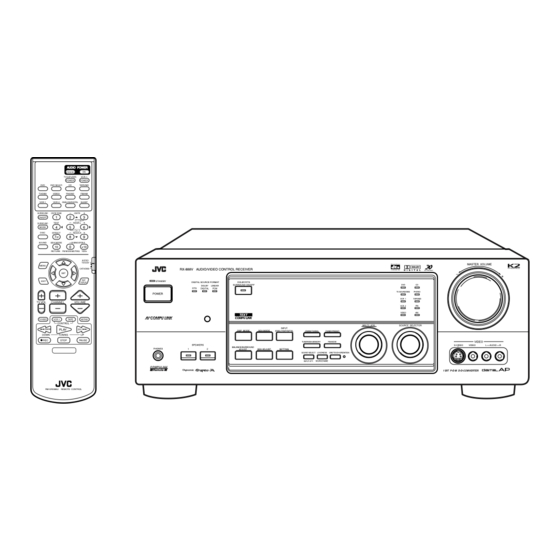
AUDIO/VIDEO CONTROL RECEIVER
RX-888VBK
STANDBY
ON
TV/CATV/DBS
VCR 1
POWER
POWER
DVD
DVD MUILTI
CD
TAPE/MD
TV/DBS
VIDEO
PHONO
FM/AM
VCR 1
VCR 2
ANALOG/DIGITAL
SLEEP
SURROUND
CNTR TONE
CNTR
1
2
3
ON/OFF
MENU
MENU
TEST
REAR-L
SURROUND
4
5
6
MODE
ENTER
ENTER
DISC
EFFECT
REAR-R
7
8
9
/P
SOUND
SEA MODE
SUBWOOFER
10
0
+10
100+
RETURN
FM MODE/MUTING
AUDIO/
TV/VCR
MENU
CATV/DBS
SET
TEXT
EXIT
STANDBY
DISPLAY
POWER
TV VOL
CHANNEL
VOLUME
TV/VIDEO
VCR 1
TAPE
MUTING
CONTROL
/REW
PLAY
FF/
DOWN
TUNING
UP
REC
STOP
PAUSE
PHONES
COMPULINK
Remote
RM-SRX888J
REMOTE CONTROL
RX-888V AUDIO/VIDEO CONTROL RECEIVER
DOLBY/DTS
DIGITAL SOURCE FORMAT
SURROUND ON/OFF
DOLBY
LINEAR
DTS
DIGITAL
PCM
INPUT
DSP MODE
SEA MODE
ANALOG/DIGITAL
FM/AM TUNING
TUNER/SEA MEMORY
SPEAKERS
BALANCE/SURROUND
1
2
ADJUST
SEA ADJUST
SETTING
SOUND SELECT
LOUDNESS
INPUT ATT.
SOURCE NAME
INSTRUCTIONS
MASTER VOLUME
D I G I T A L
–
DVD
CD
TV SOUND/DBS
PHONO
VCR 1
TAPE/MD
VCR 2
FM
VIDEO
AM
MULTI JOG
SOURCE SELECTOR
TUNER PRESET
FM MODE
S-VIDEO
ONE TOUCH OPERATION
1 BIT P-E-M D-D-COMVERTER
+
VIDEO
VIDEO
L
AUDIO
R
D I G I T A L
For Customer Use:
Enter below the Model No. and Serial
No. which are located either on the rear,
bottom or side of the cabinet. Retain this
information for future reference.
Model No.
Serial No.
LVT0175-001A
[J]
Advertisement
Table of Contents

Related Manuals for JVC RX-888VBK


Summary of Contents for JVC RX-888VBK
- Page 1 AUDIO/VIDEO CONTROL RECEIVER RX-888VBK STANDBY TV/CATV/DBS VCR 1 POWER POWER DVD MUILTI TAPE/MD TV/DBS VIDEO PHONO FM/AM VCR 1 VCR 2 ANALOG/DIGITAL SLEEP SURROUND CNTR TONE CNTR ON/OFF MENU MENU TEST REAR-L SURROUND MODE ENTER ENTER DISC EFFECT REAR-R SOUND...
- Page 2 No obstructions in 10 cm from the sides. No obstructions in 10 cm from the top. No obstructions in 15 cm from the back No obstructions, place on the level surface. Spacing 15 cm or more RX-888VBK cause harmful interference Front...
-
Page 3: Table Of Contents
Searching for a Disc (Only for the CD player) ... 39 Entering the Disc Information ... 40 AV COMPU LINK Remote Control System ... 42 Operating JVC’s Audio/Video Components ... 44 Operating Other Manufacturers’ Video Equipment ... 46 Troubleshooting ... 52... -
Page 4: Parts Identification
Refer to the pages in parentheses for details. RX-888V AUDIO/VIDEO CONTROL RECEIVER STANDBY DIGITAL SOURCE FORMAT DOLBY LINEAR SURROUND ON/OFF DIGITAL POWER SPEAKERS BALANCE/SURROUND PHONES COMPULINK Remote STANDBY TV/CATV/DBS VCR 1 POWER POWER DVD MUILTI TAPE/MD TV/DBS VIDEO PHONO FM/AM VCR 1 VCR 2 ANALOG/DIGITAL... -
Page 5: Getting Started
power supply. Before Installation General • Be sure your hands are dry. • Turn the power off to all components. • Read the manuals supplied with the components you are going to connect. Locations • Install the receiver in a location that is level and protected from moisture. -
Page 6: Connecting The Speakers
AM Antenna Connections Snap the tabs on the loop into the ANTENNA slots of the base to assemble the FM 75 AM loop. COAXIAL LOOP AM Loop Antenna Outdoor single vinyl-covered wire Turn the loop until you have the best reception. Notes: •... -
Page 7: Connecting Audio/Video Components
Connecting the rear and center speakers Connect rear speakers to the REAR SPEAKERS terminals and a center speaker to the CENTER SPEAKER terminals. CENTER SPEAKER Center speaker Left rear Right rear speaker speaker – Connecting the subwoofer speaker You can enhance the bass by connecting a subwoofer. Connect the input jack of a powered subwoofer to the SUBWOOFER OUT jack on the rear panel, using a cable with RCA pin plugs (not supplied). - Page 8 Cassette deck or MD recorder Cassette deck To audio input RIGHT LEFT MD recorder To audio input Note: You can connect either a cassette deck or an MD recorder to the TAPE/MD jacks. When connecting an MD recorder to the TAPE/MD jacks, change the source name, which will be shown on the display when selected as the source, to “MD.”...
- Page 9 Video camera The VIDEO jacks on the front panel is convenient when connecting and disconnecting the equipment frequently. VIDEO S-VIDEO VIDEO AUDIO To audio output TV and/or DBS tuner RIGHT AUDIO RIGHT To audio output Connect the TV to the MONITOR OUT jack to view the playback picture from the other connected video components.
-
Page 10: Connecting The Power Cord
Digital connections This receiver is equipped with three DIGITAL IN terminals — one digital coaxial terminal and two digital optical terminals. You can connect any component to any one of the digital terminals using the digital coaxial cable (not supplied) or digital optical cable (not supplied). -
Page 11: Basic Operations
IMPORTANT: When using the remote control, check to see if its remote control mode selector is set to the correct position: To operate an audio system, TV, and VCR, set it to “AUDIO/TV/VCR.” To operate a CATV converter and DBS tuner, set it to “CATV/DBS.”... -
Page 12: Adjusting The Volume
When playing a digital source through a digital terminal • The DIGITAL SOURCE FORMAT lamps on the front panel indicate what type of the digital signal comes into the receiver. DTS: Lights up when DTS Digital Surround signals (see page 21) come in. DIGITAL SOURCE FORMAT DOLBY DIGITAL: DOLBY... -
Page 13: Muting The Sound
Listening only with headphones 1. Connect a pair of headphones to the PHONES jack on the front panel. 2. Press SPEAKERS 1 and/or 2 so that no lamps on the buttons are turned on. CAUTION: Be sure to turn down the volume before connecting or putting on headphones, as high volume can damage both the headphones and your hearing. -
Page 14: Basic Settings
others will make operations easier. IMPORTANT: When using the remote control, check to see if its remote control mode selector is set to the correct position: To operate this receiver, set it to “AUDIO/TV/ VCR” (except when selecting the DBS tuner as the source). -
Page 15: Digital Input (Digital In) Terminal Setting
Digital Input (DIGITAL IN) Terminal Setting When you use the digital input terminals, you have to register what components are connected to which terminals (DIGITAL IN 1/2/3). Before you start, remember... • There is a time limit in doing the following steps. If the setting is canceled before you finish, start from step 1 again. -
Page 16: Setting The Speakers For The Dsp Modes
Setting the Speakers for the DSP Modes To obtain the best possible surround sound of the DSP modes, you have to register the information about the speakers arrangement after all connections are completed. Before you start, remember... • There is a time limit in doing the following steps. If the setting is canceled before you finish, start from step 1 again. -
Page 17: The Display
Crossover Frequency Setting Small speaker cannot reproduce the bass sound very well. So, if you have used a small speaker any for the front, center, or rear channels, this receiver automatically reallocates the bass elements, originally assigned to the channel for which you have connected the small speaker, to another channel (for which you have connected the large speaker). -
Page 18: Storing The Basic Settings And Adjustments - One Touch Operation
Storing the Basic Settings and Adjustments — One Touch Operation JVC’s One Touch Operation function is used to assign and store different sound settings for each different playing source. By using this function, you do not have to change the settings every time you change the source. -
Page 19: Receiving Radio Broadcasts
IMPORTANT: When using the remote control, check to see if its remote control mode selector is set to the correct position: To operate this receiver, set it to “AUDIO/TV/ VCR” (except when selecting the DBS tuner as the source). Tuning in Stations Manually On the front panel: 1. -
Page 20: Selecting The Fm Reception Mode
To tune in a preset station On the front panel: 1. Turn SOURCE SELECTOR to select the band (FM or AM). The last received station of the selected band is tuned in. 2. Press TUNER PRESET. 3. Turn MULTI JOG until you find the channel you want. -
Page 21: Using The Sea Modes
IMPORTANT: When using the remote control, check to see if its remote control mode selector is set to the correct position: To operate this receiver, set it to “AUDIO/TV/ VCR” (except when selecting the DBS tuner as the source). Selecting Your Favorite SEA Mode On the front panel: Press SEA MODE repeatedly until the SEA mode you want appears on the display. -
Page 22: Using The Dsp Modes
The 3D-PHONIC mode is the result of research on sound localization technology carried out at JVC for many years. This mode can be used when the front speakers are connected to this receiver (without respect to the rear/center speaker connection). -
Page 23: Surround Modes
(bearing the mark ), or with DTS Digital Surround DOLBY SURROUND (bearing the mark ), you can use JVC Theater Surround. • When playing a source encoded with Dolby Digital (bearing the mark ) or with DTS Digital Surround (bearing the mark D I G I T A L ), “DIG THEATER”... -
Page 24: Available Dsp Modes According To The Speaker Arrangement
Available DSP Modes According to the Speaker Arrangement Available DSP modes will vary depending on how many speakers are used with this receiver. Make sure that you have set the speaker information correctly (see page 14). Speaker arrangements Front speaker Front speaker Center speaker... -
Page 25: Adjusting The 3D-Phonic Modes
IMPORTANT: When using the remote control, check to see if its remote control mode selector is set to the correct position: To operate this receiver, set it to “AUDIO/TV/ VCR” (except when selecting the DBS tuner as the source). Adjusting the 3D-PHONIC Modes Once you have adjusted the 3D-PHONIC modes, the adjustment is memorized for each 3D-PHONIC mode. -
Page 26: Adjusting The Surround Modes
3. Adjust the effect level. 1) Press BALANCE/SURROUND ADJUST repeatedly until “DSP EFFECT” appears on the display. The display changes to show the current setting. 2) Turn MULTI JOG to select the effect level. • As you turn it, the effect level changes as follows: DSP EFFECT 1 DSP EFFECT 2... - Page 27 Notes: • You can adjust the speaker output levels without outputting the test tone. • No test tone comes out of the center speaker when “CENTER SPK” is set to “NONE” (see page 14). • No test tone comes out of the rear speakers when “REAR SPK” is set to “NONE”...
- Page 28 7. Press EFFECT to select an effect level you want. • Each time you press the button, the effect As the number increases, JVC Theater Surround becomes stronger. CNTR –/+ (from –10 dB to +10 dB). REAR•L –/+ (from –10 dB to +10 dB).
-
Page 29: Activating The Dsp Modes
DSP EFFECT 1 DSP EFFECT 2 DSP EFFECT 5 As the number increases, JVC Theater Surround becomes stronger. Activating the DSP Modes You can use only one DSP mode at a time. When a DSP mode is activated, another DSP mode is canceled if in use. - Page 30 • Each time you press the button, the DSP modes change. (See page 22 for more details.) 2. Select and play a sound source. • To enjoy 3D-PHONIC and JVC Theater Surround, play back a software: – encoded with Dolby Surround and labeled with mark.
-
Page 31: Using The Dvd Multi Playback Mode
player. Before playing back a DVD, refer also to the manual supplied with the DVD player. IMPORTANT: When using the remote control, check to see if its remote control mode selector is set to the correct position: To operate this receiver, set it to “AUDIO/TV/ VCR”... - Page 32 From the remote control: 1. Press DVD MULTI so that “DVD MULTI” appears on the display. Note: When you select “DVD MULTI” as the source to play, the DSP mode is canceled temporarily, and the SURROUND ON/OFF and SURROUND MODE buttons do not work. 2.
-
Page 33: Using The On-Screen Menus
To use this function, you need to connect the TV to the MONITOR OUT jack on the rear panel (see page 7), and set the TV’s input mode to the proper position to which the receiver is connected. • When the TV’s input mode is incorrect; for example, a different video input or TV tuner mode is selected, you cannot show the Menus on the TV screen. -
Page 34: Listening At Low Volume (Loudness)
Listening at Low Volume (Loudness) (Also see page 11) 1. Press MENU. The MAIN MENU appears on the TV. • Pressing one of the % / fi / @ / # buttons also displays the MAIN MENU. 2. Press % / fi to move to “SOUND CONTROL,”... -
Page 35: Activating The Dvd Multi Playback Mode
* “REAR R LEVEL”: Adjust the right rear speaker output level. * “CENTER TONE”: Select the center tone level. ** For JVC Theater Surround: “TEST TONE”: Output a test tone. “CENTER LEVEL”: Adjust the center speaker output level. ** “REAR L LEVEL”: Adjust the left rear speaker output... -
Page 36: Setting The Basic Setting Items
4. Press % / fi to move SEA ADJUST to “SEA ADJUST.” SEA USERMODE The SEA ADJUST menu appears. 5. Press % / fi / @ / # to adjust the SEA mode as you want. @ / # : Select the frequency ranges. % / fi... -
Page 37: Storing The Preset Stations
Storing the Preset Stations (Also see page 17) 1. Press MENU. The MAIN MENU appears on the TV. • Pressing one of the % / fi / @ / # buttons also displays the MAIN MENU. 2. Press % / fi to move to “TUNER CONTROL,”... -
Page 38: Compu Link Remote Control System
To use this remote control system, you need to connect JVC audio components through the COMPU LINK-3 (SYNCHRO) jacks (see below) in addition to the connections using cables with RCA pin plugs (see pages 5 and 6). • Make sure that the AC power cords of these components are unplugged before connection. -
Page 39: Text Compu Link Remote Control System
the CD Text* and MDs. Using these information in the discs, you can operate the CD player or MD recorder equipped with the TEXT COMPU LINK remote control system through the receiver. CONNECTIONS: To use this remote control system, you need to connect the CD player and/or MD recorder you want to operate, following the procedures below. -
Page 40: Showing The Disc Information On The Tv Screen
OPERATIONS To use this remote control system, you need to connect the TV to the MONITOR OUT jack on the rear panel (see page 7), and set the TV’s input mode to the proper position to which the receiver is connected. -
Page 41: Searching For A Disc (Only For The Cd Player)
Searching for a Disc (Only for the CD player) Search for a disc by its performer: 1. Press TEXT DISPLAY while “CD” is selected as the source. The Disc Information screen appears on the TV. 2. Press % / fi to move to “SEARCH,”... -
Page 42: Entering The Disc Information
Search for a disc by its genre: 1. Press TEXT DISPLAY while “CD” is selected as the source. The Disc Information screen appears on the TV. 2. Press % / fi to move to “SEARCH,” then press SET. The DISC SEARCH screen appears. - Page 43 4. Repeat step 3 until you finish putting a performer name (up to 32 characters). To insert a space, press % / fi / @ / # to move , then press SET. To correct an incorrect character: 1) Press % / fi / @ / # to move SET until the incorrect character is selected.
-
Page 44: Av Compu Link Remote Control System
through the receiver. To use this remote control system, you need to connect the video components you want to operate, follow the diagrams below and the procedure on the next page. CONNECTIONS 1: VCR 1 DVD player COMPU LINK COMPU LINK IMPORTANT: Connect to the terminal indicated in the illustration. - Page 45 1. If you have already plugged your VCR 1 (VCR connected to the VCR 1 jacks), DVD player, TV, and this receiver into the AC outlets, unplug their AC power cords first. 2. Connect your VCR 1, DVD player, TV, and this receiver as follows, using the cables with the monaural mini-plugs (not supplied).
-
Page 46: Operating Jvc's Audio/Video Components
IMPORTANT: To operate JVC’s audio components using this remote control: • You need to connect JVC audio components through the COMPU LINK-3 (SYNCHRO) jacks (see page 36) in addition to the connections using cables with RCA pin plugs (see pages 5 and 6). - Page 47 COMPU LINK terminals (see page 42) in addition to the connections using cables with RCA pin plugs (see pages 6 and 7). • Some JVC VCRs can accept two types of the control signals — remote code “A” and “B.” Before using this remote control, make sure that the remote control code of the VCR connected to the VCR 1 jacks is set to code “A.”...
-
Page 48: Operating Other Manufacturers' Video Equipment
1 – 9, and 0. See the list on pages 48 and 49 to find the code. Examples: For a JVC product, press 0, 5, then 3. 5. Release TV/CATV/DBS POWER. The following buttons can be used for operating the TV (with the remote control mode selector set to “AUDIO/TV/VCR”):... - Page 49 4. Enter manufacturer’s code (three digits) using buttons 1–9, and 0. See the list on page 49 to find the code. Examples: For a JVC product, press 7, 7, then 5. For a Pioneer product, press 1, 4, then 4. 5. Release TV/CATV/DBS POWER.
- Page 50 Manufacturers’ codes for TV Admiral Aiko Akai Alaron Ambassador Anam Anam National 019, 030, 052, 185 Audiovox 092, 180, 451 Baysonic Belcor Bell & Howell 016, 154 Bradford Brockwood Brocksonic 236, 463 Candle 030, 056, 186 Carnivale Carver Celebrity Cineral 092, 451 Citizen 030, 039, 056, 060, 092, 186, 280...
- Page 51 186, 187 178, 179, 180, 186 019, 180 arlite 020, 030, 054, 096 051, 250 051, 056 016, 019, 039, 054, 056, 060, 092, 150, 179, 180, 186 056, 177, 178 060, 154, 156 019, 178 ards 016, 019, 020, 021, 030, 054, 056, 096, 165, 178, 179 019, 030 016, 017, 092...
- Page 52 Manufacturers’ codes for VCR Admiral Adventura Aiko Aiwa 000, 037 Akai 041, 053, 106 American High Asha Audiovox Beaumark Bell & Howell Broksonic 002, 121, 184, 209, 211, 479 Calix Canon Capehart Carver 072, 278 Cineral Citizen 037, 278 Colt Craig 037, 047, 072, 240, 271 Curtis Mathes...
- Page 53 Singer Sony 000, 032, 033, 034, 035 Sylvania 000, 035, 043, 081 Symphonic Tatung Teac 000, 041 Technics 035, 162 Teknika 000, 035, 037 Thomas Toshiba 043, 045, 212 Totevision 037, 240 Unitech Vector Vector Research Video Concepts Videosonic Wards 000, 035, 042, 047, 048, 060, 072, 081, 149, 212, 240 White Westinghouse 278...
-
Page 54: Troubleshooting
service center. PROBLEM The display does not light up. No sound from speakers. Sound from one speaker only. Continuous hiss or buzzing during FM reception. Occasional cracking noise during FM reception. No colors on the on-screen display. Howling during record playing. “OVERLOAD”... -
Page 55: Specifications
Amplifier Output Power Audio Audio Input Sensitivity/Impedance (1 kHz): Audio Input (DIGITAL IN)* : Audio Output Level: Signal-to-Noise Ratio (’66 IHF/’78 IHF): Frequency Response (8 ohms): RIAA Phono Equalization: Loudness Control (Volume Control at –30 dB): Video Video Input Sensitivity/Impedance: Composite video: Video Output Level: Composite video:... - Page 56 FM tuner (IHF) Tuning Range: Usable Sensitivity: 50 dB Quieting Sensitivity: Signal-to-Noise Ratio (IHF-A weighted): Total Harmonic Distortion: Stereo Separation at REC OUT: Alternate Channel Selectivity: Frequency Response: AM tuner Tuning Range: Usable Sensitivity: Signal-to-Noise Ratio: General Power Requirements: Power Consumption: Dimensions (W x H x D): 87.5 MHz to 108.0 MHz Monaural:...
- Page 57 Sophisticated electronic products may require occasional service. Just as quality is a keyword in the engineering and production of the wide array of JVC products, service is the key to maintaining the high level of performance for which JVC is world famous. The JVC service and engineering organization stands behind our products.
- Page 58 WHAT WE WILL DO: If this product is found to be defective, JVC will repair or replace defective parts at no charge to the original owner. Such repair and replacement services shall be rendered by JVC during normal business hours at JVC authorized service centers.
- Page 59 VICTOR COMPANY OF JAPAN, LIMITED 0299HIMMDWJEM...