Table of Contents
Advertisement
62223
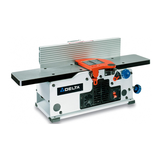
6" Variable Speed
Bench Jointer
(Model JT160)
PART NO. A05756 - 09-09-04
Copyright © 2004 Delta Machinery
To learn more about DELTA MACHINERY
RTD10000128AA
ESPAÑOL: PÁGINA 21
visit our website at: www.deltamachinery.com.
For Parts, Service, Warranty or other Assistance,
1-800-223-7278 (
1-800-463-3582).
please call
In Canada call
Advertisement
Table of Contents

Related Manuals for Delta ShopMaster JT160


Summary of Contents for Delta ShopMaster JT160
- Page 1 6" Variable Speed Bench Jointer (Model JT160) PART NO. A05756 - 09-09-04 Copyright © 2004 Delta Machinery To learn more about DELTA MACHINERY RTD10000128AA ESPAÑOL: PÁGINA 21 visit our website at: www.deltamachinery.com. For Parts, Service, Warranty or other Assistance, 1-800-223-7278 ( 1-800-463-3582).
-
Page 2: Table Of Contents
NOT be modified and/or used for any application other than for which it was designed. If you have any questions relative to its application DO NOT use the product until you have written Delta Machinery and we have advised you. -
Page 3: Safety Guidelines
SAFETY GUIDELINES - DEFINITIONS It is important for you to read and understand this manual. The information it contains relates to protecting YOUR SAFETY and PREVENTING PROBLEMS. The symbols below are used to help you recognize this information. Indicates an imminently hazardous situation which, if not avoided, will result in death or serious injury. Indicates a potentially hazardous situation which, if not avoided, could result in death or serious injury. -
Page 4: General Safety Rules
MANUAL BEFORE OPERATING THE MACHINE. accessories and attachments not recommended by Learning the machine’s application, limitations, and Delta may cause damage to the machine or injury to the specific hazards will greatly minimize the possibility of user. accidents and injury. -
Page 5: Additional Specific Safety Rules
ADDITIONAL SAFETY RULES FOR JOINTERS FAILURE TO FOLLOW THESE RULES MAY RESULT IN SERIOUS INJURY. HOLD THE WORKPIECE FIRMLY against the table DO NOT OPERATE THIS MACHINE until it is and fence. Loss of control of the workpiece can completely assembled and installed according to the cause kickback and result in serious injury. -
Page 6: Power Connections
POWER CONNECTIONS A separate electrical circuit should be used for your machines. This circuit should not be less than #12 wire and should be protected with a 20 Amp time lag fuse. If an extension cord is used, use only 3-wire extension cords which have 3- prong grounding type plugs and matching receptacle which will accept the machine’s plug. -
Page 7: Functional Description
FOREWORD Delta ShopMaster Model JT160 is a 6" (152mm), Variable-Speed Bench Jointer with a designed cutting capacity of 6" (152mm) width and 1/8" (3mm) depth. Unit includes a 10 amp, 120 volt motor with a variable speed range of 6000 to 11,000 rpm, and a cutting speed range of 12,000 to 22,000 cpm, a dust chute, a center-mounted fence, a two-knife cutterhead, a cutterhead guard and lock, wrenches, and push blocks. -
Page 8: Carton Contents
CARTON CONTENTS Fig. 4A Fig. 4 Push Blocks - (2) Jointer Fence M8 Flat Washer Cutterhead Guard Spring Loaded Lock Handle Fence Sliding Bracket M6x1x16mm Button Head Screw - (6) Fence Mounting Bracket Hex Wrench Special Nut M6x1 Square Nut - (2) Hex Wrench Cutterhead Lock UNPACKING AND CLEANING... -
Page 9: Assembly
ASSEMBLY FOR YOUR OWN SAFETY, DO NOT CONNECT THE MACHINE TO THE POWER SOURCE UNTIL THE MACHINE IS COMPLETELY ASSEMBLED AND YOU READ AND UNDERSTAND THE ENTIRE INSTRUCTION MANUAL. ASSEMBLY TOOLS REQUIRED * Two hex wrenches (supplied) ASSEMBLY TIME ESTIMATE - 30 minutes FENCE 1. -
Page 10: Cutterhead Guard
Insert a M6x1x16mm button head screw (G) Fig. 9 through fence tilting bracket (H) and thread a M6x1 square nut (J) onto threaded end of screw (G). DO NOT COMPLETELY TIGHTEN SCREW (G) AT THIS TIME. Assemble screw and square nut to opposite end of tilting bracket in the same manner. Slide groove of fence (L) Fig. - Page 11 CUTTERHEAD LOCK Assemble cutterhead lock (A) Fig. 15 to the front side of the jointer base, using the M6x1x12mm button head screw (B). NOTE: THE CUTTERHEAD LOCK (A) IS TO BE ENGAGED WITH THE CUTTERHEAD SHAFT (FIG. 15) ONLY WHEN SETTING KNIVES.
-
Page 12: Operation
OPERATION OPERATIONAL CONTROLS AND ADJUSTMENTS Fig. 21 Fig. 22 STARTING AND STOPPING JOINTER 1. The on/off switch (A) Fig. 21 is located on the front of the jointer. To turn the machine “ON”, move switch (A) up to the “ON” position. 2. -
Page 13: Depth Of Cut Adjustment
DEPTH OF CUT ADJUSTMENT The jointer can be set to cut any depth from a very thin shaving to 1/8" deep. A dual English/Metric scale (A) Fig. 24, and pointer (B) are provided to indicate the depth of cut. To adjust for depth of cut, loosen lock knob (C) and turn adjusting knob (D) clockwise to lower and coun- terclockwise to raise the infeed table. -
Page 14: Adjusting Knives
Using a square (C) Fig. 28, tilt the table to the 45 degree position and make sure the fence is 45 degrees to the table. Adjust the fence if necessary. Using supplied hex wrench (No. 10, Fig. 4A), turn set screw (H) Fig. 29, until it contacts stop (G). These positive stops enable you to rapidly position the table to the 90 and 45 degree settings. -
Page 15: Push Blocks
MATERIAL 6. If the knives are set too low, the result will be as OUT-FEED IN-FEED TABLE TABLE shown in Fig. 32, and the finished surface will be curved. KNIVES CUTTER SET TOO LOW Fig. 32 MATERIAL 7. If the knives are set too high, the work will be IN-FEED TABLE OUT-FEED gouged at the end of the cut, as shown in Fig. -
Page 16: Jointing An Edge
MACHINE USE The following directions will give the beginner a start on jointer operations. Use scrap pieces of lumber to check the settings and to get the feel of the operations before attempting regular work. NOTE: The knives on the jointer will not wear evenly by feeding the wood through the same spot on the table every time. -
Page 17: Planing Warped Pieces
WRONG FEED - AGAINST THE GRAIN Fig. 42 Fig. 43 TROUBLESHOOTING For assistance with your machine, visit our website at www.deltamachinery.com for a list of service centers or call the DELTA Machinery help line at 1-800-223-7278 (In Canada call 1-800-463-3582). -
Page 18: Belt Replacement
MAINTENANCE BELT REPLACEMENT When it becomes necessary to replace the belt on your jointer: DISCONNECT MACHINE FROM POWER SOURCE. Remove screw (A) Fig. 44, using hex wrench supplied, and remove belt guard (B). Loosen three screws (C) Fig. 45, to release belt tension and remove belt (D) from pulleys. -
Page 19: Accessories
Since accessories other than those offered by Delta have not been tested with this product, use of such accessories could be hazardous. For safest operation, only Delta recommended accessories should be used with this product. -
Page 20: Warranty
Two Year Limited New Product Warranty Delta will repair or replace, at its expense and at its option, any new Delta machine, machine part, or machine accessory which in normal use has proven to be defective in workmanship or material, provided that the customer returns the product prepaid to a Delta factory service center or authorized service station with proof of purchase of the product within two years and provides Delta with reasonable opportunity to verify the alleged defect by inspection. -
Page 21: Español
Fax: (519) 767-4131 Fax: (604) 420-3522 Fax: (514) 336-3505 The following are trademarks of PORTER-CABLE • DELTA (Las siguientes son marcas registradas de PORTER-CABLE • DELTA S.A.) (Les marques suivantes sont des marques de fabriquant de la PORTER-CABLE • DELTA): Auto-Set ®...