Table of Contents
Advertisement
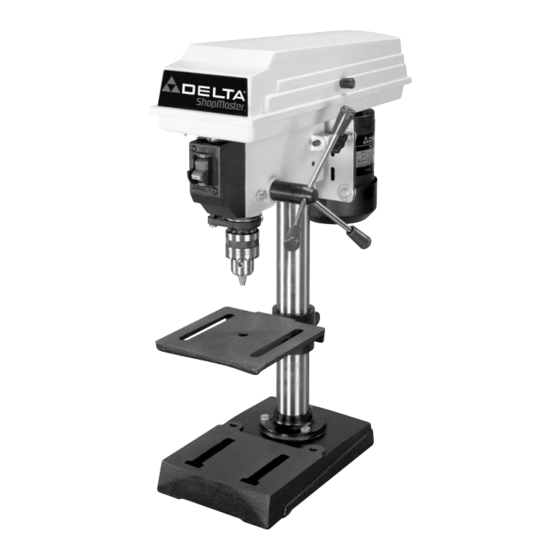
8" Drill Press
(Model DP115)
PART NO. 906580 - 07-01-02
Copyright © 2002 Delta Machinery
To learn more about DELTA MACHINERY
ESPAÑOL: PÁGINA 17
visit our website at: www.deltamachinery.com.
For Parts, Service, Warranty or other Assistance,
1-800-223-7278 (
1-800-463-3582).
please call
In Canada call
Advertisement
Table of Contents

Related Manuals for Delta ShopMaster DP115


Summary of Contents for Delta ShopMaster DP115
- Page 1 8" Drill Press (Model DP115) PART NO. 906580 - 07-01-02 Copyright © 2002 Delta Machinery To learn more about DELTA MACHINERY ESPAÑOL: PÁGINA 17 visit our website at: www.deltamachinery.com. For Parts, Service, Warranty or other Assistance, 1-800-223-7278 ( 1-800-463-3582). please call...
-
Page 2: General Safety Rules
If you have any questions relative to a particular application, DO NOT use the machine until you have first contacted Delta to determine if it can or should be performed on the product. -
Page 3: Additional Safety Rules For Drill Presses
ADDITIONAL SAFETY RULES FOR DRILL PRESSES WARNING: FAILURE TO FOLLOW THESE RULES MAY RESULT IN SERIOUS PERSONAL INJURY. 1. DO NOT OPERATE THIS TOOL UNTIL it is assembled 14. TURN THE MACHINE “OFF” AND WAIT FOR THE and installed according to the instructions. DRILL BIT, CUTTING TOOL, OR SANDER TO STOP TURNING prior to cleaning the work area, 2. -
Page 4: Motor Specifications
POWER CONNECTIONS A separate electrical circuit should be used for your machines. This circuit should not be less than #12 wire and should be protected with a 20 Amp time lag fuse. If an extension cord is used, use only 3-wire extension cords which have 3- prong grounding type plugs and matching receptacle which will accept the machine’s plug. -
Page 5: Extension Cords
Fig. D OPERATING INSTRUCTIONS FOREWORD Delta ShopMaster Model DP115 is a 8" bench drill press with a 1/4 H.P. motor. The Delta ShopMaster Model DP115 can handle most types of drill press operations. UNPACKING AND CLEANING Carefully unpack the machine and all loose items from the shipping container(s). Remove the protective coating from all unpainted surfaces. - Page 6 DRILL PRESS PARTS Fig. 2 Fig. 3 1 - Drill Press Head and Motor 5 - Chuck 2 - Column and Base Flange 6 - Chuck key 3 - Base 7 - Clamp handle 4 - Table 8 - Wrench 9 - M8x1.25x20mm Hex head screws (3) 10 - Pinion Shaft Handles (3)
- Page 7 ASSEMBLY WARNING: FOR YOUR OWN SAFETY, DO NOT CONNECT THE DRILL PRESS TO THE POWER SOURCE UNTIL THE MACHINE IS COMPLETELY ASSEMBLED AND YOU READ AND UNDERSTAND THE ENTIRE INSTRUCTION MANUAL. 1. Assemble the column (A) Fig. 4, to drill press base (B) as shown, using the three M8x1.25x20mm hex head cap screws (C).
- Page 8 5. Thread the three pinion shaft handles (H) Fig. 8, into the three holes located in the pinion shaft (J) as shown. Fig. 8 6. IMPORTANT: Make certain the spindle taper (K) Fig. 9, and tapered hole in chuck (L) are clean and free of any grease, lacquer or rust preventive coatings.
-
Page 9: Operating Controls And Adjustments
FASTENING DRILL PRESS TO SUPPORTING SURFACE If during operation there is any tendency for the machine to tip over, slide or walk on the supporting surface, the machine base must be secured to the supporting surface with a M8x1.25x125mm carriage head screw, 8.5mm flat washer, 8.5mm lock washer, M8x1.25 hex nut, through the two holes (A) Fig. -
Page 10: Table Adjustments
TABLE ADJUSTMENTS 1. The table can be raised or lowered on the drill press column by loosening the table clamp handle (A) Fig. 17. Move the table to the desired position on the column and tighten table clamp handle (A). Fig. -
Page 11: Spindle Speeds
SPINDLE SPEEDS SPINDLE MOTOR Five spindle speeds of 620, 1100, 1720, 2340 and 3100 3100 RPM are available with your drill press. Fig. 21, illustrates 2340 which step of the motor and spindle pulleys the belt must be placed to obtain the five speeds available. 1720 1100 CHANGING SPEEDS AND... -
Page 12: Operation
Use scrap material for practice to get a feel of the machine before attempting regular work. WARNING: The use of accessories and attachments not recommended by Delta may result in risk of injury. IMPORTANT: When the workpiece is long enough it should always be positioned on the table with one end against the left side of the column, as shown in Fig. -
Page 13: Correct Drilling Speeds
INSTALLING AND REMOVING DRILL BITS 1. DISCONNECT MACHINE FROM POWER SOURCE. 2. Insert smooth end of drill bit (A) Fig. 26, into chuck (B), as far as it will go, and then back the bit out 1/16", or up to the flutes for small bits. 3. -
Page 14: Parts, Service Or Warranty Assistance
Two Year Limited Warranty Delta will repair or replace, at its expense and at its option, any Delta machine, machine part, or machine accessory which in normal use has proven to be defective in workmanship or material, provided that the customer returns the product prepaid to a Delta factory service center or authorized service station with proof of purchase of the product within two years and provides Delta with reasonable opportunity to verify the alleged defect by inspection. - Page 15 NOTES...
- Page 16 NOTES...