Advertisement
Table of Contents
- 1 Safety Rules
- 2 Unpacking and Cleaning
- 3 Assembly Instructions
- 4 Power Connections
- 5 Grounding Instructions
- 6 Extension Cords
- 7 Operating Controls and Adjustments
- 8 Locking Switch in the "Off" Position
- 9 Adjusting Depth Stop Rod
- 10 Adjusting Fence
- 11 Adjusting Chisel Parallel to Workpiece
- 12 Operation
- 13 Parts, Service or Warranty Assistance
- Download this manual
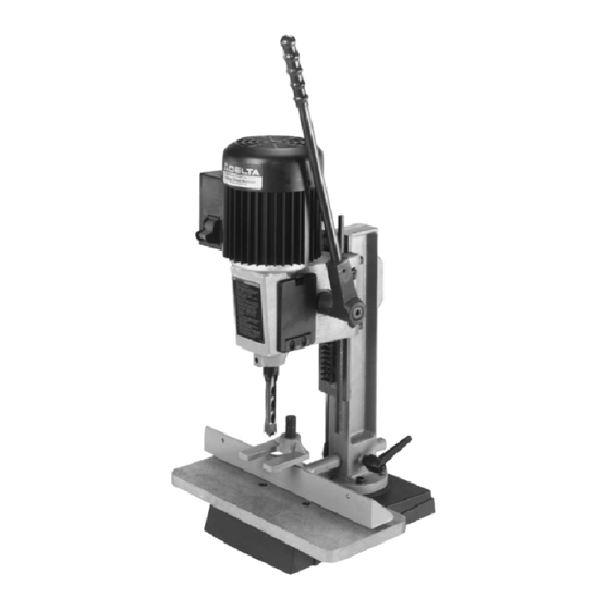
Hollow Chisel
Mortiser
(Model 14-650)
PART NO. 900651 (011)
Copyright © 2001 Delta Machinery
To learn more about DELTA MACHINERY
ESPAÑOL: PÁGINA 19
visit our website at: www.deltamachinery.com.
For Parts, Service, Warranty or other Assistance,
1-800-223-7278 (
1-800-463-3582).
please call
In Canada call
Advertisement
Table of Contents

Related Manuals for Delta 14-650


Summary of Contents for Delta 14-650
- Page 1 Hollow Chisel Mortiser (Model 14-650) PART NO. 900651 (011) Copyright © 2001 Delta Machinery To learn more about DELTA MACHINERY ESPAÑOL: PÁGINA 19 visit our website at: www.deltamachinery.com. For Parts, Service, Warranty or other Assistance, 1-800-223-7278 ( 1-800-463-3582). please call...
-
Page 2: Safety Rules
If you have any questions relative to a particular application, DO NOT use the machine until you have first contacted Delta to determine if it can or should be performed on the product. - Page 3 (tools, scrap pieces, etc.). 18. THE USE of attachments and accessories not 5. ALWAYS keep hands, fingers and hair away from recommended by Delta may result in the risk of injuries. the rotating bit. 19. ADDITIONAL INFORMATION regarding the safe 6.
-
Page 4: Unpacking And Cleaning
UNPACKING AND CLEANING Carefully unpack the mortiser and all loose items from the carton. Remove the protective coating from the machined surfaces of the mortiser. This coating may be removed with a soft cloth moistened with kerosene. Do not use acetone, gasoline, or lacquer thinner for this purpose. -
Page 5: Assembly Instructions
ASSEMBLY INSTRUCTIONS WARNING: FOR YOUR OWN SAFETY, DO NOT CONNECT THE MACHINE TO THE POWER SOURCE UNTIL THE MACHINE IS COMPLETELY ASSEMBLED AND YOU HAVE READ AND UNDERSTOOD THE ENTIRE OWNER’S MANUAL. ASSEMBLING RAISING AND LOWERING HANDLE 1. Assemble hub of handle assembly (A) Fig. 3, to end of pinion shaft (B) and fasten handle to pinion shaft using special screw (C) and spring (D). - Page 6 2. Fig. 6, illustrates the hydraulic cylinder (B) assembled to the machine. The hydraulic cylinder (B) keeps the head in the up position. Fig. 6 ASSEMBLING TABLE 1. Assemble the table (A) Fig. 7, to the base using the two M6 x 35mm flat head screws (B) and T-nuts (C). Insert the two screws (B) into the two holes (D) in table board (A).
- Page 7 2. Thread stud (D) Fig. 9, into hole on side of column, as shown. Do not thread stud (D) all the way into hole at this time. 3. Reassemble handle (C) Fig. 9, on stud (D) and re- place screw (A) and spring (B). Fig.
- Page 8 7. Assemble the holddown (H) Fig. 13, onto bar (F) as shown, and tighten set screw (J) against flat on bar. Fig. 13 ASSEMBLING TOOL AND CHISEL HOLDER 1. Assemble tool and chisel holder (A) Fig. 14, to side of column using the two M6 x 25mm screws (B) and flat washers as shown.
-
Page 9: Power Connections
CONNECTING MORTISER TO POWER SOURCE POWER CONNECTIONS A separate electrical circuit should be used for your tools. This circuit should not be less than #12 wire and should be protected with a 20 Amp time lag fuse. If an extension cord is used, use only 3-wire extension cords which have 3- prong grounding type plugs and 3-pole receptacles which accept the tool’s plug. -
Page 10: Extension Cords
EXTENSION CORDS MINIMUM GAUGE EXTENSION CORD RECOMMENDED SIZES FOR USE WITH STATIONARY ELECTRIC TOOLS Use proper extension cords. Make sure your extension Ampere Volts Total Length of Gauge of cord is in good condition and is a 3-wire extension cord Rating Cord in Feet Extension Cord... - Page 11 4. Push bit (A) Fig. 23, up through chisel and into chuck (G) as far as it will go, and then back the bit off 1/16", and lock bit in chuck using chuck key supplied. Fig. 23 5. Loosen set screw (D) Fig. 24, and push chisel (B) up against bottom of bushing (E), as shown, and tighten set screw (D).
-
Page 12: Operating Controls And Adjustments
OPERATING CONTROLS AND ADJUSTMENTS SWITCH The switch (A) Fig. 26, is located on the side of the motor. To start the mortiser, move the switch (A) to the up position. To turn the mortiser “OFF” move the switch to the down position Fig. -
Page 13: Adjusting Depth Stop Rod
ADJUSTING DEPTH STOP ROD A depth stop rod (A) Fig. 29, is provided to limit the depth of the chisel (B). To adjust the depth stop rod (A), loosen screw (C) and lower head until the chisel (B) is at the desired depth. Lower depth stop rod (A) until it contacts base (D) and tighten screw (C). -
Page 14: Operation
ADJUSTING SLIDING FIT BETWEEN HEAD AND COLUMN A dovetail gib (A) Fig. 32, is provided on the rear of the head to insure a good sliding fit between the head and the column when the head is raised and lowered. Adjustment is made by loosening the two screws (B) and turning adjusting screws (C). - Page 15 USING AUXILIARY WOOD FENCE When mortising extra high workpieces (A) Fig. 35, an auxiliary fence (B) can be fastened to the fence (C) with wood screws (D) through the two holes in the fence. This provides additional support for the workpiece during the mortising operation.
- Page 16 USING BITS WITH EXTRA LONG SHANKS When using bits with extra long shanks, it will be necessary to remove the extension (A) Fig. 37. This can be accomplished by inserting screwdriver into center hole Fig. 37 of motor end cap (B) Fig. 38, and into slot in end of armature shaft.
- Page 17 NOTES...
-
Page 18: Parts, Service Or Warranty Assistance
PARTS, SERVICE OR WARRANTY ASSISTANCE All Delta Machines and accessories are manufactured to high quality standards and are serviced by a network of Porter- Cable•Delta Factory Service Centers and Delta Authorized Service Stations. To obtain additional information regarding your Delta quality product or to obtain parts, service, warranty assistance, or the location of the nearest service outlet, please call 1-800-223-7278, (In Canada call 1-800-463-3582).