Extron electronics System 5 IP Series User Manual
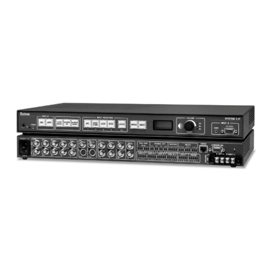
System switchers with integrated a/v switching, audio amplification, and projector control
Hide thumbs
Also See for System 5 IP Series:
- Specification sheet (3 pages) ,
- Setup manual (27 pages) ,
- Manual (2 pages)
Table of Contents
Advertisement
Quick Links
Download this manual
See also:
Setup Manual
Advertisement
Table of Contents

Related Manuals for Extron electronics System 5 IP Series


Summary of Contents for Extron electronics System 5 IP Series
- Page 1 System 5 IP Series System Switchers with Integrated A/V Switching, Audio Amplification, and Projector Control 68-611-01 Rev. D 05 06...
- Page 2 Precautions Safety Instructions • English Warning Power sources • This equipment should be operated only from the power source indicated on the product. This This symbol is intended to alert the user of important operating and maintenance equipment is intended to be used with a main power system with a grounded (neutral) conductor. The (servicing) instructions in the literature provided with the equipment.
-
Page 3: Table Of Contents
Table of Contents Chapter 1 • Introduction ...................... 1-1 About the System 5 IP Series Switchers .............. 1-2 Video and audio features ....................1-2 Video ............................ 1-2 Audio ............................ 1-2 Control features ........................ 1-2 Controlling the switcher ...................... 1-2 Controlling other devices ....................1-3... - Page 4 Table of Contents, cont’d Global Configurator Software for Windows ® ........... 4-7 IR Learner ™ Software for Creating Customized IR Driver Files ....4-7 Embedded Web Pages ..................... 4-8 Status ..........................4-9 System Status ........................4-9 Statistics ..........................4-9 Configuration ........................4-10 File Management ......................
- Page 5 Appendix A • Reference Material .................. A-1 Specifications ........................A-2 Part Numbers and Accessories ................. A-6 Included parts ........................A-6 Accessories ........................A-6 Cables ..........................A-7 Audio Block Diagram ...................... A-8 Glossary ..........................A-9 Appendix B • Firmware Updates ..................B-1 Determining the Firmware Version ................
-
Page 6: Table Of Contents, Cont'd
Table of Contents, cont’d System 5 IP Switchers • Table of Contents... -
Page 7: Chapter 1 • Introduction
System 5 IP Switchers Chapter One Introduction About the System 5 IP Series Switchers How the System 5 IP Works: System 5 IP Components and Interactions... -
Page 8: About The System 5 Ip Series Switchers
Introduction About the System 5 IP Series Switchers The Extron System 5 IP switchers are five input, one output, active, audio/video (A/V) switchers capable of controlling a projector and various other items such as lights, a projector lift, or a screen motor. Throughout this manual they are referred to as the System 5 IP, the switcher, or System 5. -
Page 9: Controlling Other Devices
As an integrated part of the System 5 IP switchers, IP Link provides these advantages: Global compatibility — The switcher uses standard Ethernet communication protocols, including ARP, DHCP, ICMP (ping), TCP/IP, Telnet, HTTP, and SMTP. Embedded Web page serving — IP Link ™... -
Page 10: How The System 5 Ip Works: System 5 Ip Components And Interactions
Introduction, cont’d How the System 5 IP Works: System 5 IP Components and Interactions Unlike previous models of Extron system switchers or the Extron MediaLink Controller (MLC 206), the System 5 IP requires and uses event files to perform all functions except basic input switching and volume control. -
Page 11: Chapter 2 • Installation: Labeling, Mounting, Cabling
System 5 IP Switchers Chapter Two Installation: Labeling, Mounting, Cabling UL/Safety Requirements Installing or Replacing Button Labels Mounting the System 5 IP Rear Panels and Cabling Front Panel Cabling... -
Page 12: Ul/Safety Requirements
Installation: Labeling, Mounting, Cabling UL/Safety Requirements The Underwriters Laboratories (UL) requirements listed below pertain to the safe installation and operation of a System 5 IP Switcher. Do not use the switcher near water or expose it to liquids. To reduce the risk of fire or electric shock, do not expose this apparatus to rain or moisture. -
Page 13: Mounting The System 5 Ip
Mounting the System 5 IP Rack mount the switcher, if desired, using the included rack mounting kit (part #70-077-03), which is factory installed. Otherwise, affix the four rubber feet (included) to the corners of the bottom of the switcher for use on a tabletop. Rack mounting For rack mounting, do not install the rubber feet. -
Page 14: Rear Panels And Cabling
Installation: Labeling, Mounting, Cabling, cont’d Rear Panels and Cabling Power, A/V input, and video output connections 100-240V 1.3A R/VID PROJ CONT IR/SERIAL OUT CM/IR/SCP RS-232 Tx Rx G S G S G S G S G CM IR SCP R/VID 50-60Hz Power connector —... -
Page 15: Audio Output Connections And Reset Switch
Audio output connections and reset switch CONFIG/RS-232 RELAYS RIGHT LEFT L LINEOUT R L PREAMP R (Amplifier Models Only) Lineout and Preamp audio outputs — Connect an audio output device to either connector for line level audio outputs. The Lineout and Preamp audio outputs are simultaneously active. - Page 16 Installation: Labeling, Mounting, Cabling, cont’d Connect the sleeve to ground. Connecting the sleeve to a negative (-) CAUTION terminal will damage the audio output circuits. Mono output is selected via RS-232 or the front panel. If mono output is selected, a mono audio signal is output on both channels (left and right). If an output connector is wired for balanced output, the level will be 6 dB higher than if the connector is wired for unbalanced output.
- Page 17 This connector outputs either stereo (left and right) or dual mono channels. The two mono output audio channels are identical. If you intend to connect just one speaker, you should set the amplifier to output a mono signal. The amplifier’s power supply is separate from the switcher’s main power supply.
-
Page 18: Resetting The Unit
Installation: Labeling, Mounting, Cabling, cont’d Resetting the unit There are four reset modes (numbered 1, 3, 4, and 5 for the sake of comparison with an Extron IPL product) that are available by pressing the Reset button on the rear panel. The Reset button is recessed, so use a pointed stylus, ballpoint pen, or Extron Tweeker to access it. -
Page 19: Control Connections
Control connections CONFIG/RS-232 RELAYS PROJ CONT IR/SERIAL OUT CM/IR/SCP RS-232 Tx Rx G S G S G S G S G CM IR SCP RIGHT LEFT L LINEOUT R L PREAMP R Projector control (Proj Cont) RS-232 port (-5 VDC to +5 VDC) — Connect a cable between the projector/display and the left three poles of this 3.5 mm captive screw connector for RS-232 one- or two-way control. - Page 20 Installation: Labeling, Mounting, Cabling, cont’d IR/Serial Output ports — Depending on how the switcher is configured via the configuration software, these ports output either infrared signals or unidirectional RS-232 signals for controlling various devices such as VCRs and DVD players. Before it can be used for controlling a device, each port must be set up via the configuration software for either IR or RS-232 communication and associated with a device driver.
- Page 21 CM/IR/SCP port — You can connect up to four Extron control modules (IRCMs, ACMs, RCMs), one Extron IR Link infrared signal repeater, and/or up to two Extron SCP control pads to this port to allow remote control of the System 5 IP switcher or other items. A maximum of seven devices can be connected to this port.
- Page 22 Installation: Labeling, Mounting, Cabling, cont’d Relay ports (24 V, 1 A) — These six relays allow control of items such as room lighting, window coverings, and display screens. These contacts may be used to control any equipment as long as the contact specifications of a total of 24 volts at 1 ampere are not exceeded for each port.
- Page 23 • Use a straight- Clip Down Straight-through Cable 1 2 3 4 5 6 7 8 RJ-45 through cable (for connection to a switch, hub, or router) connector for connection End 1 End 2 to a switch, Wire Color Wire Color hub, or router.
-
Page 24: Front Panel Cabling
Installation: Labeling, Mounting, Cabling, cont’d Front Panel Cabling SYSTEM 5 IP INPUT 5 PC VIDEO AUDIO CONFIG Config port — This 2.5 mm mini stereo jack serves the same function as the rear panel Configuration/RS-232 port, but it is easier to access than the rear port after the switcher has been installed in a rack and cabled. - Page 25 Input 5 — This input allows convenient Tip (L) access for a laptop computer. The Ring (R) 15-pin HD connector accepts RGB computer video, and the 3.5 mm mini stereo jack accepts unbalanced stereo audio input. The audio plug can be wired Sleeve ( ) as shown at right.
- Page 26 Installation: Labeling, Mounting, Cabling, cont’d 2-16 System 5 IP Switchers • Installation: Labeling, Mounting, Cabling...
-
Page 27: Chapter 3 • Front Panel Features And Basic Operation
System 5 IP Switchers Chapter Three Front Panel Features and Basic Operation Front Panel Features Optimizing the Audio Front Panel Security Lockout (Executive Modes) LCD Menus and Basic Switcher Setup... -
Page 28: Front Panel Features
Front Panel Features and Basic Operation A System 5 IP can be set up and operated by using: • The front panel controls. • A computer, a touch screen panel, or any other device that can send and receive the serial communications through the RS-232 port. •... -
Page 29: Buttons
Config port — This port is a front panel version of the rear panel Configuration/RS-232 port, and it is independent of the rear panel port. This port makes it possible to upload and configure device drivers and also to initiate IR learning via a front panel connection after the switcher has been installed. -
Page 30: Adjustment Features And Input 5
Front Panel Features and Basic Operation, cont’d Function/room control buttons — These buttons can be set up to control the switcher’s relays, and they can also be set up to execute IR or RS-232 commands of your choice. The relays can be used to control items in the room such as a projector lift, screen motor, or lighting. -
Page 31: Optimizing The Audio
LCD screen — This screen displays basic system status, menu, and configuration information. You will use it primarily during switcher configuration. During regular operation, the LCD displays the volume level. Volume/Adjust knob and Min/Mid/Max LEDs — Rotate this knob to adjust the volume when the switcher is in regular user mode, and use it to select options from menus in switcher setup mode. -
Page 32: Configuring The Preamp Output Level
Front Panel Features and Basic Operation, cont’d Configuring the Preamp output level Prior to adjusting any input levels, an output level must be selected from the following options. You will not need to change the output level if the Preamp output will not be used. -
Page 33: Front Panel Security Lockout (Executive Modes)
Adjust the switcher’s input level via the front panel (FPC model only) or the embedded factory default Web pages (either model) until the desired output level is reached and/or the Mid/normal LED turns on. Increasing the audio level beyond the point at which the Mid/normal LED flashes may result in a distorted output signal. -
Page 34: Lcd Menus And Basic Switcher Setup
Front Panel Features and Basic Operation, cont’d LCD Menus and Basic Switcher Setup You can configure some basic settings (video type, RGB delay, audio input gain, bass and treble levels, audio balance, mode, and output level settings) and control the output volume by using the LCD, the Menu and Next buttons, and the Volume/Adjust knob. - Page 35 Volume Select the video type. Input 1 and input 2 only: RGB or video (composite Set the switching delay or S-video). period for RGB signals. MENU Selecting inputs 3, 4, or 5 0 seconds to 5 seconds displays the video type. in 0.5 second increments VIDEO Video 2...
- Page 36 Front Panel Features and Basic Operation, cont’d 3-10 System 5 IP Switchers • Front Panel Features and Basic Operation...
-
Page 37: Configuring The Hardware
System 5 IP Switchers Chapter Four Software- and Web Page-based Setup and Control Configuring the Hardware ® Global Configurator Software for Windows IR Learner ™ Software for Creating Customized IR Driver Files Embedded Web Pages ™ Controlling the System 5 IP via GlobalViewer Web Pages... -
Page 38: Chapter 4 • Software- And Web Page-Based Setup And Control
Software- and Web Page-based Setup and Control A System 5 IP switcher must be configured before use. The System 5 IP can operate as a stand-alone audio/video switcher without being configured, but without configuration the switcher will not be able to control other devices. The System 5 IP switcher can be configured and controlled via a host computer attached to the rear panel Config/RS-232 port or LAN port, or the front panel Config port. -
Page 39: Setting Up The Pc For Ip Communication
Setting up the PC for IP communication You need a Windows-based (Windows NT, 2000, XP, or higher) PC equipped with an operating network adapter. To allow your PC to work with Extron’s Ethernet- controlled products, the TCP/IP protocol must be installed and properly configured. - Page 40 Software- and Web Page-based Setup and Control, cont’d Write down the PC’s current IP address and subnet mask below. If your PC is set to “Obtain an IP address automatically,” make a note of that, instead. You will need to restore these settings to the PC later. IP address: Subnet mask: Change the PC’s IP address so it can communicate with the System 5 IP and...
-
Page 41: Setting Up The System 5 Ip Switcher (At Initial Startup) For Ip Communication
Setting up the System 5 IP switcher (at initial start-up) for IP communication When you power on the System 5 IP for the first time, there are three ways to set up the switcher’s IP address: • Use the ARP command. •... -
Page 42: Configuring The Switcher Via A Web Browser
Software- and Web Page-based Setup and Control, cont’d Execute a ping command by entering “ping” followed by a space and the new IP address at the command prompt. For example: ping 10.13.170.15 The response should show the switcher’s new IP address, as shown below. You can reconnect using either Telnet or a Web browser to verify that the update was successful. -
Page 43: Configuring The Switcher Via The Global Configurator Software
conventions/protocol. The IP network administrator should provide the IP addresses and subnet mask to be used with this switcher. It takes a minute or so for the switcher to store the new settings. (See the configuration section of “Embedded Web Pages” in this chapter and also the Global Configurator Help file for details about settings.) Once the switcher’s IP address is changed, you lose communication with the switcher. -
Page 44: Embedded Web Pages
Software- and Web Page-based Setup and Control, cont’d Embedded Web Pages The System 5 IP switcher features an embedded Web server, which includes factory set Web pages. These pages can be replaced with user-designed files, but the default Web pages provide many basic features for monitoring, configuring, and controlling the switcher via a Web browser. -
Page 45: Status
Status System Status This Web page provides information on settings. Changes must be made via the Configuration Web page or via the configuration software or SIS programming. Personnel who have user access can view this page but do not have access to configuration pages. -
Page 46: Configuration
Software- and Web Page-based Setup and Control, cont’d A typical Statistics Web page Configuration There are five Configuration Web pages, which only administrators can access: • System Settings for IP, date/time, and executive mode setting changes 4-10 System 5 IP • Software- and Web Page-based Setup and Control... - Page 47 • Audio and Video Adjustments, which corresponds to the configuration program’s Audio/Video Configuration tab Video output may turn off briefly (for the duration of the RGB delay setting) while you set the video configuration for inputs 1 and 2 or when you press the front panel Menu and Next buttons and enter the Video Config menu, whether or not you make any changes to the configuration.
- Page 48 Software- and Web Page-based Setup and Control, cont’d • Email Alerts provides a way to add e-mail addresses of people or departments to be notified of various events, and this page also provides a way to associate an existing e-mail file with each e-mail address. The e-mail files have to be created separately, though.
-
Page 49: File Management
File Management This Web page displays a list of files stored on the System 5 IP. It also allows those with administrator access to load additional files into the switcher or delete files. The File Management page allows you to sort by file type (see the Filter by File Extension or Select drop-down menu). -
Page 50: Files Stored On The Pc Only And Used To Generate Files For The Switcher
Software- and Web Page-based Setup and Control, cont’d of the file contains the body of the e-mail. For the System 5 IP, these files are numerically named (1 through 64). For example, 1.eml, 2.eml, 3.eml,... 64.eml. ___.evt — These are event files, the most important files for the functioning of the switcher. -
Page 51: Control
Control • User Mode — The first of the Control Web pages is User Mode, which is a representation of the switcher’s front panel buttons, volume control, and also of any optional control modules (IRCMs, RCMs, ACMs) that are part of the system. Clicking on a button on screen emulates a button press on the corresponding device. - Page 52 Software- and Web Page-based Setup and Control, cont’d A User Mode Web page for a System 5 IP with an MPS 112 switcher slaved to it • IR Drivers — This Web page lists IR driver files only and allows you to select a file to see and execute the commands stored in them.
- Page 53 An example for a specific IR driver is shown in the following screen picture. • Serial Devices — To see a page of simulated buttons you can click to control each RS-232-configured device, click on the name of the desired port (Display Port, Port A, Port B, Port C, or Port D).
-
Page 54: Controlling The System 5 Ip Via Globalviewer
Software- and Web Page-based Setup and Control, cont’d ™ Controlling the System 5 IP via GlobalViewer Web Pages The System 5 IP switcher can be used as part of a network of devices based on Extron IP Link ™ technology, such as IP Link interfaces. Global Configurator (GC) is a Windows-based program used for configuring and customizing the Web browser- based GlobalViewer ™... -
Page 55: Monitor
Monitor A typical GlobalViewer Monitor page • The Monitor window on the right side of the screen displays information on what things (projector disconnection, lamp hours, and the like) are being monitored, under what conditions, and whom will receive an e-mail notification about each condition. -
Page 56: Info
Software- and Web Page-based Setup and Control, cont’d Info A GlobalViewer Info page showing a disconnected projector A GlobalViewer Info page showing a connected projector • The IP Link Global Viewer window at the left of the screen shows a list of IP Link-based devices within the network that have Global Viewer Web pages installed. -
Page 57: Chapter 5 • Sis ™ Programming And Control
System 5 IP Switchers Chapter Five ™ Programming and Control Host-to-switcher Communications Commands and Reponses... -
Page 58: Host-To-Switcher Communications
System 5 IP responds by sending a message to the host. No response is required from the host. The switcher-initiated messages are listed here (underlined). (c)Copyright 2006, Extron Electronics, SYSTEM5IP, Vx.xx Day, DD Mon YYYY HH:MM:SS Vx.xx is the firmware version number. -
Page 59: Password Information
• If the System 5 IP is on, it sends the boot and copyright messages when you first open a Telnet connection to the System 5 IP. You can see the day of the week, date, and time if the System 5 IP is connected via Telnet, but not via RS-232. If you are using a Telnet connection, the copyright message, date, and time are followed by a password prompt. -
Page 60: Commands And Reponses
™ Programming and Control, cont’d Commands and Reponses Using the command/response tables The System 5 IP can be controlled via either a Telnet (port 23) connection or a Web browser (port 80) connection. The ASCII and URL commands listed in the tables starting on page 5-8 perform the same functions, but they are encoded differently to accommodate the requirements of each port (Telnet or browser). -
Page 61: Symbol Definitions
Switcher’s name. The name is a text string of up Symbol definitions to 24 characters drawn from the alphabet (A- = CR/LF (carriage return/line feed) (hex 0D 0A) Z), digits (0-9), and minus sign/hyphen (-). No blank or space characters are permitted as = Carriage return (no line feed, hex 0D) part of a name. - Page 62 ™ Programming and Control, cont’d Baud rate: 300, 600, 1200, 1800, 2400, 3600, 4800, For the CR command, = filename of the 7200, 9600, 14400, 19200, 28800, 38400, 57600, or e-mail file to be sent, e.g. 1.eml, 2.eml, ... 64.eml 115200 The filename must be x.eml where x is a number Parity (only the first letter is needed):...
- Page 63 = Specific input number (0 - 5) = Power sensor signal pin status X200 X214 0 = 0 input (no connection) 00 = voltage is low (threshold 0.6 V) 1 = input 1 01 = voltage is high (threshold 0.7 V) 2 = input 2 Leading zeros will be used in responses to 3 = input 3...
- Page 64 ™ Programming and Control, cont’d ™ System 5 IP • SIS Programming and Control...
- Page 65 ™ System 5 IP • SIS Programming and Control...
- Page 66 ™ Programming and Control, cont’d ™ 5-10 System 5 IP • SIS Programming and Control...
- Page 67 ™ System 5 IP • SIS Programming and Control 5-11...
- Page 68 ™ Programming and Control, cont’d ™ 5-12 System 5 IP • SIS Programming and Control...
- Page 69 ™ System 5 IP • SIS Programming and Control 5-13...
- Page 70 ™ Programming and Control, cont’d ™ 5-14 System 5 IP • SIS Programming and Control...
- Page 71 ™ System 5 IP • SIS Programming and Control 5-15...
- Page 72 ™ Programming and Control, cont’d ™ 5-16 System 5 IP • SIS Programming and Control...
- Page 73 ™ System 5 IP • SIS Programming and Control 5-17...
- Page 74 ™ Programming and Control, cont’d ™ 5-18 System 5 IP • SIS Programming and Control...
- Page 75 ™ System 5 IP • SIS Programming and Control 5-19...
- Page 76 ™ Programming and Control, cont’d ™ 5-20 System 5 IP • SIS Programming and Control...
- Page 77 ™ System 5 IP • SIS Programming and Control 5-21...
- Page 78 ™ Programming and Control, cont’d ™ 5-22 System 5 IP • SIS Programming and Control...
- Page 79 ™ System 5 IP • SIS Programming and Control 5-23...
- Page 80 ™ Programming and Control, cont’d ™ 5-24 System 5 IP • SIS Programming and Control...
- Page 81 ™ System 5 IP • SIS Programming and Control 5-25...
- Page 82 ™ Programming and Control, cont’d ™ 5-26 System 5 IP • SIS Programming and Control...
- Page 83 ™ System 5 IP • SIS Programming and Control 5-27...
- Page 84 ™ Programming and Control, cont’d ™ 5-28 System 5 IP • SIS Programming and Control...
- Page 85 ™ System 5 IP • SIS Programming and Control 5-29...
- Page 86 ™ Programming and Control, cont’d ™ 5-30 System 5 IP • SIS Programming and Control...
- Page 87 ™ System 5 IP • SIS Programming and Control 5-31...
-
Page 88: Command/Response Table For Special Function Sis Commands
™ Programming and Control, cont’d The syntax for setting a special function for a System 5 IP switcher is * __ # where is the value and __ is the function number. To view a function’s setting, use __#, where __ is the function number. In the following table the values of the variable are different for each command/function. - Page 89 Command/response table for special function SIS commands, continued Command ASCII Command Response values (host to System 5) (System 5 IP to host) and additional descriptions Power amp limit *56 # AmpLimit* Limit amplifier output when volume is at maximum level. 0 = 0 dB attenuation (default), 1 = 1 dB attenuation, 2 = 2 dB attenuation,...
- Page 90 ™ Programming and Control, cont’d Command/response table for special function SIS commands, continued Command ASCII Command Response values (host to MLC) (MLC to host) and additional descriptions Button associations (virtual mapping) for an IRCM-DV+ By design an IRCM-DV+ can be assigned paired module addresses (by DIP switch) of either 1&2 or 3&4 only. It cannot be assigned to addresses 2&3 or 1&4.
- Page 91 Command/response table for special function SIS commands, continued Command ASCII Command Response values (host to Syst. 5IP) (switcher to host) and additional descriptions Miscellaneous settings Enable switcher slaving *41 # Slave* , 0 = disable (default), 1 = enable slave control of an Extron MPS 112CS switcher.
- Page 92 ™ Programming and Control, cont’d Command/response table for special function SIS commands, continued Command ASCII Command Response values (host to MLC) (MLC to host) and additional descriptions Button press/release emulation Emulating a button press or release causes the commands and actions that are associated with the button via the main event script to be executed.
-
Page 93: Button/Switch Memory Block Numbering
Command/response table for special function SIS commands, continued Command ASCII Command Response values (host to Syst. 5IP) (switcher to host) and additional descriptions Each control module (IRCM, ACM, RCM) has 20 memory blocks reserved for it, no matter how many buttons are physically present on the module: •... - Page 94 ™ Programming and Control, cont’d Command/response table for special function SIS commands, continued Command ASCII Command Response values (host to MLC) (MLC to host) and additional descriptions Input switching lockouts Lock out input switching during power on/off * 53 # PrwLock* This command prevents input switching during display warm...
-
Page 95: Chapter 6 • Special Applications
System 5 IP Switchers C hapter Six Special Applications Working with Combination Source Devices Adding User-Defined RS-232 Commands Routing Audio to an External Amplifier and a Volume Controller Slaving an MPS 112 Switcher to a System 5 IP... -
Page 96: Working With Combination Source Devices
Special Applications Working With Combination Source Devices Many combination DVD-VCR players can output the video signals from both the video tape and the DVD parts on a single port. If you connect this single output to one input on the System 5 IP switcher, the switcher has no way to automatically know whether it receives input from the DVD or from the VCR;... -
Page 97: Using Ircm Control Modules For Dvd-Vcr Control
Using IRCM control modules for DVD-VCR control The output of a combination DVD-VCR player can be connected to a single input of the System 5 IP, and you can install and configure Extron control modules such as the IRCM-DVD or IRCM-DVD+, and an IRCM-VCR to control the separate sources within the combination device. - Page 98 Special Applications, cont’d To configure the switcher for an IRCM-DV+ and DVD-VCR control, follow this procedure: See chapter four and refer to the System 5 IP Setup Guide for instructions on how to use Global Configurator software. The instructions in this section assume that you have a basic understanding of how to start a project and perform basic setup tasks using Global Configurator.
- Page 99 Click the Button Modes selection list and select toggle mode. If desired, configure function/room button 2’s lights. Click Add below the Button Operations area at the bottom of the GC window. The Add Button Operation window appears. Configure the function/room button to light green (or another color of your choice) on the first (Action #1) press, as shown in the picture below, and click OK.
- Page 100 Special Applications, cont’d Configure the function/room button to light red (or another color of your choice) on the second (Action #2) press, and click OK. Associate the DVD half of the IRCM-DV+ with input 3 for the first press of function/room button 1.
- Page 101 If needed, add commands from the DVD-VCR driver to each press/release action (1 and 2) for the Room 2 button. You might want to assign a DVD command and a Play command to the first press/release and to assign a VCR command and a Play command to the second press/release.
- Page 102 Special Applications, cont’d In the IP Link tab area, click on the address of one half of the IRCM-DV+ module. A configuration page for that part (DVD or VCR) of the module appears in the area to the right of the IP Link view. Click the Auto Fill Control Module/System Remote button.
-
Page 103: Adding User-Defined Rs-232 Commands
Adding User-Defined RS-232 Commands ™ The Extron drivers used by the System 5 IP and other IP Link -enabled products contain most commands needed for a given device. However, occasionally an installation requires a user-defined RS-232 command that was not supplied with the standard driver. -
Page 104: Routing Audio To An External Amplifier And A Volume Controller
Special Applications, cont’d Select User Defined as the type of operation. See the screen shot below. Select the port via which the command will be sent to the display or source device. In the Command space below the port selection menu, enter the command as an ASCII character string. -
Page 105: Slaving An Mps 112 Switcher To A System 5 Ip
100-240V 1.3A CONFIG/RS-232 R/VID PROJ CONT IR/SERIAL OUT CM/IR/SCP RELAYS RS-232 Tx Rx G S G S G S G S G CM IR SCP L LINEOUT R L PREAMP R R/VID 50-60Hz Extron System 5 IP System Switcher MVC 121 MAIN 3 FIXED MIXER/VOLUME... -
Page 106: Connecting The System 5 Ip And Mps 112
Special Applications, cont’d Configuring the System 5 for switcher slaving Cable and power on the System 5 IP, the MPS 112, and a host PC. Refer to “Connecting the System 5 IP and MPS 112” in this chapter. On the host PC, start the Global Configurator program, and open the appropriate project file. - Page 107 System 5 IP Switchers A ppendix A Reference Material Specifications Part Numbers and Accessories Audio Block Diagram Glossary...
-
Page 108: Appendix A • Reference Material
Reference Material Specifications Video Gain ..........Unity Bandwidth ........350 MHz (-3 dB), fully loaded Differential phase error ....1º at 3.58 MHz and 4.43 MHz Differential gain error ....1% at 3.58 MHz and 4.43 MHz Crosstalk ........-68 dB @ 10 MHz, -39 dB @ 100 MHz Switching speed ...... -
Page 109: Audio Input
Standards ........TTL (RGB), NTSC 3.58, NTSC 4.43, PAL, SECAM Input level ........2.0 V to 5.0 Vp-p Output level ........5.0 Vp-p, unterminated Input impedance ......10k ohms Output impedance ...... 75 ohms Max input voltage ....... 5.0 Vp-p Max. - Page 110 Reference Material, cont’d Nominal level ....... -10 dBV (316 mV) or +4 dBu (1.23 V) (configurable) Maximum level (600 ohm) ..>+18 dBu, balanced at 1%THD+N Unbalanced wired outputs will have unity gain/attenuation. Balanced outputs will result in a 6 dB gain. Audio output —...
- Page 111 Control — peripheral equipment IR/serial control ports ....(4) 3.5 mm captive screw connectors, 2-pole Programmable: RS-232 (±5 V), or TTL level (0 to 5 V) infrared up to 1 MHz IR learning frequencies ....30 kHz to 62 kHz IR learning distance .....
-
Page 112: Part Numbers And Accessories
Reference Material, cont’d Part Numbers and Accessories Included parts These items are included in each order for a System 5 IP switcher: Included parts Replacement part number System 5 IP with amplifier, with FPC (1) 60-397-81 System 5 IP without amplifier, with FPC (1) 60-397-83 System 5 IP with amplifier, without FPC (1) 60-397-82... -
Page 113: Cables
Control accessories Part number IR Emitter 19-823-01 IR Broadcaster 60-272-01 Current/display power sensor 60-271-01 IR Link IR signal repeater (gray, black, white) 60-404-01, -02, -03 IR 402 remote control (1) 70-207-01 SCP 150 (gray, black, white) 60-495-01, -02, -03 SCP 150 AAP (gray, black, white) 60-496-01, -02, -03 IRCM-VCR (gray, black, white) 70-148-01, -02, -03... -
Page 114: Audio Block Diagram
Reference Material, cont’d Audio Block Diagram CTRL LEFT CHN LINEOUT LEFT RIGHT CHN RIGHT CTRL LEFT CTRL Per Input VOLUME Gain/Attenuation MONO Adjustment CTRL LEFT PREAMP BASS & TREBLE RIGHT BASS & TREBLE +/-10dB@ 100Hz/10kHz MONO -40dB to +30dB RIGHT VOLUME CONTROL User Mode: Volume Level Indicator... -
Page 115: Glossary
Glossary 10/100Base-T is Ethernet which uses unshielded twisted pair (UTP – Cat 5, etc.) cable, where the amount of data transmitted between two points in a given amount of time is equal to either 10 Mbps or 100 Mbps. Address Resolution Protocol (ARP) is a protocol which assigns an IP address to a device based on the device’s MAC or physical machine address. - Page 116 Reference Material, cont’d the Internet, a table (see ARP) relates the device’s IP address to its corresponding physical (MAC) address on the LAN. Pass-through allows control systems to work with the switcher and provides a link between two ports. Ping (ICMP) is a utility/diagnostic tool that tests network connections. It is used to determine if the host has an operating connection and is able to exchange information with another host.
-
Page 117: Appendix B • Firmware Updates
System 5 IP Switchers A ppendix B Firmware Updates Determining the Firmware Version Updating the Main Firmware Updating FPGA Firmware... -
Page 118: Determining The Firmware Version
Firmware Updates If the need arises, you can replace the Extron System 5 IP switcher’s main firmware via an IP connection without opening the unit or changing firmware chips. It is unlikely that you will need to replace the FPGA firmware chip, which controls the switcher’s hardware (ports, relays), but it can be replaced after opening the unit. - Page 119 Connect the switcher to a PC via an Ethernet connection, or connect the switcher and the PC to a network/LAN. See chapters two and four of this manual and read the System 5 IP Setup Guide for details. ® Start a Web browser program (such as Microsoft Intenet Explorer or Netscape ®...
-
Page 120: Updating The Main Firmware
Firmware Updates, cont’d Updating the Main Firmware The PC and the switcher must both be connected to an Ethernet network in order to update the main firmware. Firmware upgrades can be performed via IP only. You may wish to save the existing configuration to a file (see chapter four) before replacing the firmware. -
Page 121: Updating Fpga Firmware
In the Choose file dialog box, locate and select the firmware file you downloaded to C:\Program Files\Extron \Firmware\System_5_IP \xx, and click the Open button. Click on the Web page’s Upload button to upload the firmware into the switcher. It takes a while to load all the files into the switcher. You will not see any on-screen indication when the upload has finished. - Page 122 Firmware Updates, cont’d Locate chip U8 on the circuit board, as shown in the following illustrations. Align Notches 0 -2 1 .3 R /V G /Y B /C -6 0 R /V G /Y V ID B /C V ID Y /C Y /C -2 3...
- Page 123 Align the slots of the new FPGA chip with the socket in the same orientation as the old chip. Gently but firmly press the chip into place in the socket. Replace the top cover on the switcher, and fasten it with the screws that were removed in step 3.
- Page 124 Firmware Updates, cont’d System 5 IP Switchers • Firmware Updates...
- Page 125 Extron’s Warranty Extron Electronics warrants this product against defects in materials and workmanship for a period of three years from the date of purchase. In the event of malfunction during the warranty period...
- Page 126 Kyodo Building Anaheim, CA 92805 3821 AH Amersfoort PM Industrial Building 16 Ichibancho The Netherlands Singapore 368363 Chiyoda-ku, Tokyo 102-0082 Japan 714.491.1500 +31.33.453.4040 +65.6383.4400 +81.3.3511.7655 www.extron.com Fax +65.6383.4664 Fax +81.3.3511.7656 Fax 714.491.1517 Fax +31.33.453.4050 © 2006 Extron Electronics. All rights reserved.