American Dynamics SpeedDome Ultra Camera Installation And Service Manual
Hide thumbs
Also See for SpeedDome Ultra Camera:
- Installation and service manual (61 pages) ,
- Operating instructions (5 pages) ,
- Specifications (2 pages)

Related Manuals for American Dynamics SpeedDome Ultra Camera


Summary of Contents for American Dynamics SpeedDome Ultra Camera
-
Page 1: Camera Dome
SpeedDome Ultra ® Camera Dome Installation and Service Manual 8000-1362-01, Rev. C... - Page 2 SpeedDome Ultra ® Camera Dome Installation and Service Manual 8000-1362-01, Rev. C MDR 6/97...
-
Page 3: Fcc Compliance
FCC COMPLIANCE This equipment has been tested and found to comply with Part 15 of the FCC Rules. Operation is subject to the following two conditions: 1) this device may not cause harmful interference, and 2) this device must accept any interference received, including interference that may cause undesired operation. -
Page 4: Table Of Contents
TABLE OF CONTENTS PREFACE..................................V CHAPTER 1 INTRODUCTION ..........................1-1 ..............................1-2 BOUT THE Main Components ..............................1-2 Camera Options..............................1-2 Optional Slot Cover ............................... 1-2 Basic Geneology ..............................1-2 Indoor Mounting Methods ............................. 1-4 Outdoor Mounting Method ............................ 1-6 Features .................................. 1-6 ................................ - Page 5 CHAPTER 4 SERVICE ............................4-1 ..............................4-2 EFORE EGIN Tools and Equipment Required..........................4-2 ............................. 4-2 OUTINE ROUBLESHOOTING ........................... 4-5 ETAILED ROUBLESHOOTING ..........................4-5 ISASSEMBLY ECHNIQUES How to Remove the CPU Board ..........................4-6 How to Remove the P/S Board ..........................4-6 How to Remove the Pan Motor..........................
-
Page 6: Preface
Installation and service of this camera dome does not require detailed knowledge of how it works or its circuits. However, if this information is required, order the following document. Theory for SpeedDome Ultra Camera Domes, document number 8000-1670-01. Questions? For technical support or questions that this manual does not... -
Page 7: Chapter 1 Introduction
CHAPTER SpeedDome Ultra Camera Dome INTRODUCTION CHAPTER 1 n About the Dome................1-2 Describes how the dome works, its mounting methods, major components, and features. n Specifications ................1-9 Lists electrical, environmental, regulatory, and mechanical specifications for the dome. SPEEDDOME ULTRA... -
Page 8: About The Dome
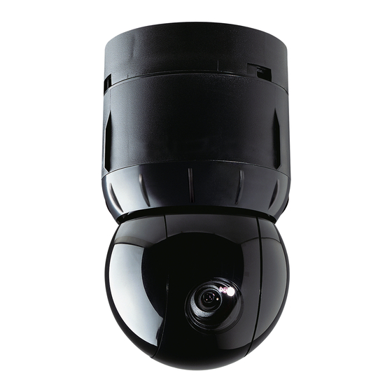
About the Dome Used in place of the slot cover mounted on the eyeball, The SpeedDome Ultra camera dome (Figure Chapter 1- this optional slot cover has a 0.5f darker lens to enhance 1) is part of a programmable network of camouflaged eyeball camouflage. - Page 9 INTRODUCTION Figure Chapter 1-2. Dome components 0400-0833-01 Housing Assy. Screws (3), M3 x 8 PHP (5801-1051-120) 0100-1340-01 Base Assy. Cap (0500-7256-01) Base (0500-7257-01) CPU Board (0301-0578-01) Ground Clip (0500-7293-01) Screw (4), M3 x 6 (5813-2041-113) I/O Board Standoff (3), M3 x 8H x 13L (5899-0055-01) (0301-0546-01) Shield (0500-7192-01) Dust Cover...
-
Page 10: Indoor Mounting Methods
INTRODUCTION Indoor Mounting Methods Mounting Structures (Optional) The dome’s base can be mounted to many indoor The dome’s base mounts directly to indoor hard or tile mounting structures (Figure Chapter 1-5) that attach to ceilings using hardware supplied with the dome, or to indoor walls and ceilings. - Page 11 INTRODUCTION Figure Chapter 1-5. Indoor mounting structures (optional) RHIUH RHIUFB RHIUAB RHIUWM RHIUCM RHIULWM RHIUPND RHIU3x3, RHIU4x4 RHSDA SPEEDDOME ULTRA...
-
Page 12: Outdoor Mounting Method
INTRODUCTION • DSP Motor Control. All lens motors are assembled Outdoor Mounting Method on a balanced mechanism that supports high-speed pan and tilt movements. Digital signal processing The RHSDA adapter bracket facilitates dome mounting (DSP) and dynamic motor braking assure precise to an an existing outdoor SpeedDome housing. -
Page 13: Video System Dependent Features
• Sensormatic Video Manager system with RS422 • Console V-phase adjustment • Sensormatic VM8, VM16, or VM96 systems • Address range from 1 to 16. • American Dynamics AD2083-02 system. Following are features associated with each type of VM96 System system. - Page 14 INTRODUCTION • RS422 communications test pushbutton and Installation & Service Features LEDs. A pushbutton and green and red LEDs on the In alphabetical order: underside of an installed base allow the installer to check RS422 terminations to the dome. The LEDs •...
-
Page 15: Specifications
INTRODUCTION Regulatory Specifications Emmisions ......FCC Part 15, Subpart B Class A Operational EN55022 Class B (CE) Manual Pan/Tilt Speed ..1° to 100° per second Immunity.......EN50082-1 (CE) (scaled to zoom position) Safety........UL2044 Target Pan/Tilt Speed ..220° per second maximum CSA 22.2 No. - Page 16 INTRODUCTION Camera Field-of-View Formulas: Horizontal view = (.87 x a)/b Monochrome/Color Vertical view = (.634 x a)/b Type........ Interline transfer 1/4” CCD array where a = distance from camera in meters or feet Scanning System..... 2:1 interlace where b = zoom power (such as 12X) Video Out .......
- Page 17 CHAPTER “Indoor” SpeedDome Ultra Camera Dome INSTALLATION CHAPTER 2 In this chapter: n Before You Begin ..............2-2 Things you need to do before you install the camera dome. n Installation Procedure ..............2-3 Shows you how to mount the dome indoors to either a hard ceiling, tile ceiling, wall, electrical box, I-beam, or existing SpeedDome housing.
-
Page 18: Chapter 2 "Indoor" Installation
INDOOR INSTALLATION Parts Check Before You Begin Other than these instructions, in the shipping box for the dome are the following parts: Safety • Base assembly, 0100-1340-01 ALWAYS USE: • Housing and eyeball assembly, 0100-1036-01 • Installation kit, 0351-1109-01. • Proper safety equipment for the location and •... -
Page 19: Procedure
INDOOR INSTALLATION Install Kit Supplied Installation Procedure 0351-1109-01* Anchor, plastic 2880-0073-01 This section explains how to install the camera Washer, flat, LOD M4 5842-0300-020 dome indoors. Screw, STAP, AB, 4.2 x 32, PHP 5810-4091-120 * Only parts used in this procedure are listed. How to Use this Section Procedure 1. - Page 20 INDOOR INSTALLATION Tile Ceiling Surface Mounting Figure Chapter 2-4. Mounting clip attachment This procedure explains how to mount the dome’s base directly to the T-bar intersection of a tile ceiling. After completing this procedure, go to page 2-18 for dome setup and attachment procedures. Install Kit Supplied 0351-1109-01* Clip, T-bar...
-
Page 21: Optional Mounting Structures
INDOOR INSTALLATION Optional Mounting Structures Procedure The following sections explain how to assemble Ensure that the ceiling or wall (particu- larly sheet rock) can support the dome. various mounting structures to which the dome’s base will mount. Note: If attaching the housing to a mounting struc- Top Hat Housing ture, assemble the structure, then skip step 1 of this procedure and go to step 2. -
Page 22: Indoor Installation
INDOOR INSTALLATION “Fixed” Mounting Bracket for Hard Mounting Structures Required Ceilings or 2x2 Ceiling Tiles 01RHIUH Top Hat Housing* Housing, top hat 0500-7455-01 The fixed mounting bracket enables the dome to * Only part used in this procedure is listed. be recessed in a hard ceiling or 2x2 ceiling tile. - Page 23 INDOOR INSTALLATION Procedure Steps 8 through 17 are for ceiling tiles only! 8. Loosely attach clips [e] to the side support Ensure that the ceiling (particularly brackets using washers [f] and nuts [g]. sheet rock) can support the dome. 9. Center side support brackets against T-bars. Referring to Figure Chapter 2-7: To easily center the assembly in the open space, ensure that the V-notch in each side support bracket...
- Page 24 INDOOR INSTALLATION “Adjustable” Mounting Bracket for Mounting Structures Required 2x4 Ceiling Tiles 01RHIUH Top Hat Housing* Housing, top hat 0500-7455-01 The adjustable mounting bracket enables the dome * Only part used in this procedure is listed. to be recessed in a ceiling tile whose shortest 01RHIUAB Adjustable Brkt.
- Page 25 INDOOR INSTALLATION Procedure 6. Tighten the clips to secure the assembly to the T-bars. Also tighten the extension sup- ports to the support bracket. Ensure that the tile ceiling can support the dome. 7. Seat the modified ceiling tile in the opening. 8.
- Page 26 INDOOR INSTALLATION Wall Mount Structure Procedure This procedure explains how to assemble and Referring to the Figure Chapter 2-9: mount the dome’s wall mount structure to a wall. After completing this procedure, go to page 2-18 1. Place bracket [a] on wall, level, and mark for dome setup and attachment procedures.
- Page 27 INDOOR INSTALLATION Wall Mount Structure with Corner Figure Chapter 2-10 shows the mounting assembly. Annotations refer to items in the install kit. Feature Figure Chapter 2-10. Mounting assembly This procedure explains how to assemble and mount the dome’s wall mount structure with corner feature to an inside corner, wall, or outside corner.
- Page 28 INDOOR INSTALLATION Procedure 2. Anchor by performing step a, b, or c (Figure Chapter 2-13). Refer back to Figure Chapter 2-10 while performing this procedure: To sheet rock: Use anchor hardware [f]. To wood: Use washer [h], and screw [j]. 1.
- Page 29 INDOOR INSTALLATION Arm Extension Structure with Corner Figure Chapter 2-14 shows the mounting assembly. Annotations refer to items in the install kit. Feature Figure Chapter 2-14. Mounting assembly This procedure explains how to assemble and mount the dome’s arm extension structure with corner feature to an inside corner, wall, or outside corner.
- Page 30 INDOOR INSTALLATION Procedure 2. Anchor by performing step a, b, or c (Figure Chapter 2-17). Refer back to Figure Chapter 2-14 while performing To sheet rock: Use anchor hardware [g]. this procedure: To wood: Use washer [i], and screw [k]. 1.
-
Page 31: Hard Ceiling Pendent Mount
INDOOR INSTALLATION Hard Ceiling Pendent Mount 4. Secure the plate using clamps [b], screws [c], washers [d], and locking nuts [e]. Refer The following procedure explains how to secure the to base plate hole-to-hole dimensions in dome’s base to a either a ceiling I-beam or hard Figure Chapter 2-18. -
Page 32: Electrical Box Attachment
INDOOR INSTALLATION Procedure 5. Attach flange using washers [d] and locking nuts [e]. Referring to Figure Chapter 2-19: 6. Thread nipple [h] into the flange. 1. Attach cover [a] to the electrical box using 7. Thread pipe tee [g] into nipple. screws [b]. -
Page 33: Adapter Bracket For Indoor Speeddome Housings
INDOOR INSTALLATION Adapter Bracket for Indoor 2. Feed cables as shown, then attach the adapter bracket to the existing dome SpeedDome Housings housing (Figure Chapter 2-21). The following procedure explains how to use an Seat the ball of the lanyard hanging from the adapter bracket to mount the dome’s base in an adapter bracket into the bracket at the top of the existing... -
Page 34: Dome Setup And Attachment
INDOOR INSTALLATION Dome Setup and Attachment 4. Connect the alarm input cable, if used. Route this cable through the board’s cable clamp The following procedure explains how to connect and connect its wires to the P4 connector on the I/O board as follows: cables to the I/O board, check cable connections, attach the I/O board to the dome’s base, set the... - Page 35 INDOOR INSTALLATION 5. Connect the alarm output cable, if used. Figure Chapter 2-23. I/O board and pushbutton Route this cable through the board’s cable clamp and connect its wires to the P3 connector on the I/O board as follows: P3 Connector (Alarm Outputs) RS422 Test Pushbutton Color...
- Page 36 INDOOR INSTALLATION If required, use the dome’s address 13. Detach the dome and reset the rotary switches to set the dome’s special features switches for the dome address. (Figure Chapter 2-25). The dome address can be set from 001 to 255. If you direct the dome to move left and it moves right, 14.
-
Page 37: Skirt And Bubble Attachment
INDOOR INSTALLATION Skirt and Bubble Attachment Attaching the Bubble to the Top Hat Housing (No Skirt Used) The following procedures show you how to attach skirts and bubbles to a top hat housing or indoor Install Kit Required (pick Kit A, B, C, or D) SpeedDome housing. -
Page 38: Attaching The Bubble To The Indoor Speeddome Housing
INDOOR INSTALLATION Attaching the Skirt to the Indoor Attaching the Bubble to the Indoor SpeedDome Housing (No Bubble SpeedDome Housing Used) The following procedure explains how to attach a bubble to an indoor SpeedDome housing. The following procedure explains how to attach a skirt to an indoor SpeedDome housing. - Page 39 INDOOR INSTALLATION Using the Install/Removal Tool Procedure The RHIRT install/removal tool eliminates the need Referring to Figure Chapter 2-30, insert the tool into for a ladder during routine service. The tool can be the top of the pole and maneuver until it snaps in used to: place.
- Page 40 INDOOR INSTALLATION Figure Chapter 2-30. How to use the install/removal tool Skirt or Bubble Attachment/Detachment Catch the notch and pull down. Snap tool into pole. Attachment Detachment Dome Attachment (Reverse steps to detach) Line up Line up Turn until you feel a click.
- Page 41 CHAPTER “Outdoor” SpeedDome Ultra Camera Dome INSTALLATION CHAPTER 3 In this chapter: n Before You Begin ..............3-2 Things you need to do before you install the camera dome. n Installation Procedure ..............3-3 Shows you how to mount the dome to an existing outdoor SpeedDome housing.
-
Page 42: Chapter 3 "Outdoor" Installation
OUTDOOR INSTALLATION Parts Check Before You Begin Other than these instructions, in the shipping box for the dome are the following parts: Safety • Base assembly, 0100-1340-01 • Housing and eyeball assembly, 0100-1036-01 ALWAYS USE: • Installation kit, 0351-1109-01. • Proper safety equipment for the location and •... -
Page 43: How To Use This Section
OUTDOOR INSTALLATION Installation Procedure This section explains how to install the camera dome in an outdoor SpeedDome housing. How to Use this Section 1. Mount the dome’s base in the outdoor housing: Mounting the dome’s base in the outdoor SpeedDome housing....... 3-4 2. -
Page 44: Mounting The Dome's Base In The Outdoor Speeddome Housing
3. Find the data/power cable from the outdoor interface board. Remove the connector from this cable. 4. Mount the SpeedDome Ultra camera dome’s base to the adapter bracket [a] (Figure Chapter 3-2). Use two of six screws [e] to attach the base to the bracket. -
Page 45: Dome Setup And Attachment
OUTDOOR INSTALLATION Dome Setup and Attachment 4. Connect the alarm input cable, if used. Route this cable through the board’s cable clamp The following procedure explains how to set up and and connect its wires to the P4 connector on the I/O attach the dome to its base. - Page 46 OUTDOOR INSTALLATION 5. Connect the alarm output cable, if used. Figure Chapter 3-5. I/O board LEDs and pushbutton Route this cable through the board’s cable clamp and connect its wires to the P3 connector on the I/O board as follows: P3 Connector (Alarm Outputs) RS422 Test Color...
- Page 47 OUTDOOR INSTALLATION If required, use the dome’s address 13. Detach the dome and reset the rotary switches to set the dome’s special features switches for the dome address. (Figure Chapter 3-7). The dome address can be set from 001 to 255. If you direct the dome to move left and it moves right, 14.
-
Page 48: Skirt And Bubble Attachment
OUTDOOR INSTALLATION Skirt and Bubble Attachment The following procedures show you how to attach a skirt and bubble to the outdoor SpeedDome hous- ing. Procedure Referring to Figure Chapter 3-9: 1. Push pins of the skirt [a] into their respec- tive receptacles and snap the skirt into place. - Page 49 CHAPTER CHAPTER CHAPTER CHAPTER SpeedDome Ultra Camera Dome SERVICE CHAPTER 4 In this chapter: n Before you begin ..............4-2 Explains things you need to do and tools you need to have on hand before you service the camera dome. n Routine Troubleshooting............4-2 Contains procedures to help you isolate a problem to the base or housing and eyeball assembly.
-
Page 50: Before You Begin
SERVICE Tools and Equipment Required Before You Begin To service the dome, you should have on hand the This chapter contains two troubleshooting proced- following equipment: ures: • Dome Software (latest version) • Routine troubleshooting • Phillips-head screwdriver • Detailed troubleshooting. •... - Page 51 SERVICE Procedure 4. Isolate the problem to the dome or its base. If another base is nearby, detach the dome and Perform steps in sequence until the problem is reattach it to the other base. Does it display video or corrected.
- Page 52 SERVICE 6. On the I/O board in the base, observe the 8. If using RS422 communications, check the green power LED (Figure Chapter 4-3). comm. line connections on the I/O board. Is the green LED off or not on steady? If using RS422 communications, press and hold the pushbutton shown in Figure Chapter 4-3 and −...
-
Page 53: Dome Functions But Does Not Tilt
SERVICE Dome Functions but Does Not Tilt Detailed Troubleshooting If the dome functions but does not tilt, you need to access the camera/lens board (see page 4-9) Use this procedure if: and/or tilt motor (see page 4-10). • The dome functions but does not pan On the camera/lens board, is the tilt motor’s cable •... -
Page 54: How To Remove The Cpu Board
SERVICE How to Remove the CPU Board How to Remove the P/S Board Referring to Figure Chapter 4-4. Referring to Figure Chapter 4-5. 1. Remove the cap. 1. Perform the procedure “How to Remove the CPU Board” (this page). Remove the three Phillips head screws holding the cap in place, then “gently”... -
Page 55: How To Remove The Pan Motor
SERVICE How to Remove the Pan Motor How to Remove the Slot Covers Referring to Figure Chapter 4-6. 1. Insert a small slotted screwdriver (Figure Chapter 4-7). 1. Perform the procedure “How to Remove the Swivel the eyeball so that one of the two slot covers CPU Board”... -
Page 56: How To Remove The Camera
SERVICE How to Remove the Camera How to Detach the Eyeball 1. Perform the procedure “How to Remove the 1. Perform the procedure “How to Remove the Slot Covers” (page 4-7). Slot Covers” (page 4-7). 2. Remove the ribbon cable from the camera 2. - Page 57 SERVICE How to Remove the The following steps refer to Figure Chapter 4-15. Camera/Lens Board 6. Access the camera/lens board. To do this, loosen the captive retaining screw holding 1. Perform the procedure “How to Remove the the bearing assembly in place and remove this Slot Covers”...
-
Page 58: How To Remove The Tilt Motor
SERVICE How to Remove the Tilt Motor 6. Access the tilt motor. To do this, loosen the captive retaining screw holding the tilt cable assembly in place and gently remove 1. Perform the procedure “How to Remove the this assembly. Slot Covers”... -
Page 59: Setting The Dome Address
SERVICE Setting the Dome Address Dome Maintenance Recessed at the top of the dome assembly are three rotary switches (Figure Chapter 4-20) which Updating/Reprogramming enable the dome address to be changed from 001 to 255. Dome Software Figure Chapter 4-20 To update or reprogram dome software: 1. - Page 60 AMERICAN DYNAMICS Sensormatic CCTV Systems Division One Blue Hill Plaza Pearl River, NY 10965 Technical Support Center 1-800-442-2225 Business (914) 624-7600 SENSORMATIC ELECTRONICS 951 Yamato Road Boca Raton, FL 33431-4425 Technical Support Center 1-800-543-9740 Business (561) 989-7000...