Table of Contents
Advertisement
Quick Links
Check the Extron Web site (www.extron.com) for updates.
Left Side
PROJECTOR
ON
LIGHT
OFF
ON
VOLUME
LIGHT
OFF
LAPTOP
AUTO
IMAGE
Front
Rear
C 1 2
C 3 4
C 5 6
A
B
C
PROJECTOR
A B C D E
RELAYS
CM/ IR SCP
RS-232/IR
Bottom
(rotated 180 degrees)
MLC 226 Series
MediaLink
PRELIMINARY
AUX
DVD
VCR
VIDEO
1
2
3
4
5
6
LECTERN
PC
PC
IR
CONFIG
Right Side
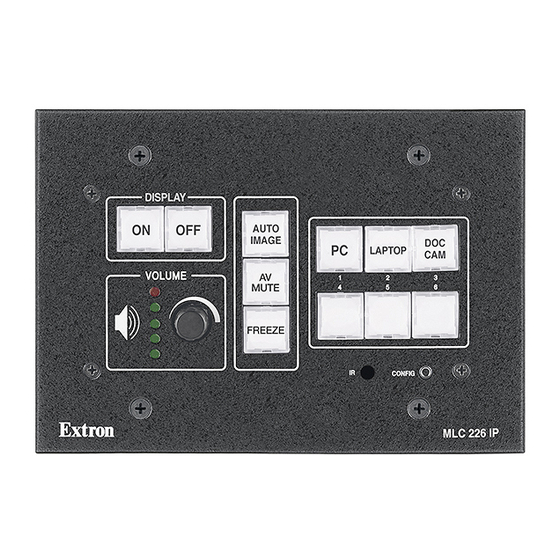
MLC 226 IP
HOST
CONTROL
1=D INPUT 2=Tx 3=Rx
5=GND, 38400, N, 8, 1
PRESS TAB WITH
TWEEKER TO REMOVE
S G
S G
S G
A
B
C
A B
IR/SERIAL OUT
MLS PWR
RS-232 12V
™
Controllers
68-955-01 Rev. A
11 04
Advertisement
Table of Contents

Related Manuals for Extron electronics MLC 226 Series


Summary of Contents for Extron electronics MLC 226 Series
- Page 1 C 1 2 C 3 4 C 5 6 PROJECTOR A B C D E RELAYS IR/SERIAL OUT MLS PWR CM/ IR SCP RS-232/IR RS-232 12V Bottom (rotated 180 degrees) MLC 226 Series ™ MediaLink Controllers 68-955-01 Rev. A 11 04...
- Page 2 Precautions Safety Instructions • English Warning This symbol is intended to alert the user of important operating and maintenance Power sources • This equipment should be operated only from the power source indicated on the product. This equipment is intended to be used with a main power system with a grounded (servicing) instructions in the literature provided with the equipment.
-
Page 3: Table Of Contents
Table of Contents Chapter 1 • Introduction ...................... 1-1 About the MLC 226 Series MediaLink™ Controllers ........1-2 MLC 226 Series features ....................1-2 Additional features for MLC 226 IP models ..............1-2 Controlling other devices ....................1-2 How the MLC 226 Series Controllers Work: MLC Components and Interactions ................. - Page 4 Using the help program ....................4-39 Embedded Web Pages ....................4-40 Status: System Status ...................... 4-41 Configuration ........................4-42 File Management ......................4-43 Control ..........................4-44 Controlling the MLC 226 IP via Global Viewer ™ ..........4-47 MLC 226 Series • Table of Contents...
- Page 5 Included parts ........................A-4 Accessories ........................A-4 Cables ..........................A-6 Glossary ..........................A-7 All trademarks mentioned in this manual are the properties of their respective owners. 68-955-01 Rev. A Printed in the USA 11 04 MLC 226 Series • Table of Contents...
-
Page 6: Table Of Contents, Cont'd
Table of Contents, cont’d MLC 226 Series • Table of Contents... -
Page 7: Chapter 1 • Introduction
MLC 226 MediaLink ™ Controllers Chapter One Introduction About the MLC 226 Series MediaLink™ Controllers How the MLC 226 Series Controllers Work: MLC Components and Interactions... -
Page 8: About The Mlc 226 Series Medialink Controllers
Controlling other devices The MLC 226 Series offers two methods of projector and source device control: RS-232 or infrared (IR). The MLC can learn IR signals from remote controls to communicate with sources such as VCRs and DVD players. Users can create their own device drivers (IR or RS-232) or go to the Extron Web site (www.extron.com) -
Page 9: How The Mlc 226 Series Controllers Work: Mlc Components And Interactions
How the MLC 226 Series Controllers Work: MLC Components and Interactions Unlike the Extron MediaLink Controller (MLC 206 Series), the MLC 226 Series requires and uses event files to perform all functions except basic input switching and volume control. The event files define, monitor, and govern how an MLC 226 Series controllerworks. - Page 10 Scripts are compiled to generate the main event file to monitor any button press or release and to generate the actions (issuing commands, triggering relays, switching inputs) associated with the buttons. MLC 226 Series • Introduction...
- Page 11 MLC 226 MediaLink ™ Controllers Chapter Two Installation: Labeling, Cabling, Mounting UL/Safety Requirements Installing or Replacing Button Labels Panels and Cabling Side Panel Features: Reset Button and LED Pinout Guide Mounting the MLC...
-
Page 12: Ul/Safety Requirements
Align the tabs on the MLC with the notches on the backing plate. Gently but firmly press the reassembled button into place in the MLC’s or SCP’s front panel. Repeat steps 1 to 8 as needed to relabel other buttons. MLC 226 Series • Installation: Labeling, Cabling, Mounting... -
Page 13: Panels And Cabling
The pin assignments of this – Digital I/O connector are as follows: Transmit data Receive data – No connection Signal ground 6, 7 – No connection DB9 Pin Locations 8, 9 – No connection Female MLC 226 Series • Installation: Labeling, Cabling, Mounting... - Page 14 RS-232 up to 250 feet (76 m) away, but the RS-232 response levels of that device may be too low for the MLC to be able to detect. MLC 226 Series • Installation: Labeling, Cabling, Mounting...
-
Page 15: Bottom/Rear Panel And Cabling
Digital input: pin 1 and the ground pin together act as a digital input port (depending on configuration). This allows for an additional way to trigger events or functions (such as triggering relays, issuing commands, or sending an e-mail). MLC 226 Series • Installation: Labeling, Cabling, Mounting... - Page 16 Refer to the appropriate device’s user’s manual. The control modules, IR Link, and SCPs can be daisy chained, as shown in the following diagram. Extron Comm-Link cable is recommended for these connections. MLC 226 Series • Installation: Labeling, Cabling, Mounting...
- Page 17 Any SCP control pad or control modules (CM, IRCM, ACM, RCM) used with the MLC will be affected by front panel security lockout (executive mode) status changes. MLC 226 Series • Installation: Labeling, Cabling, Mounting...
- Page 18 You can also use SIS commands or the configuration software to specify pulse duration. Via the configuration software, each relay can be associated with a front panel button, or it can be operated independently. MLC 226 Series • Installation: Labeling, Cabling, Mounting...
- Page 19 IR Emitter 1 S = Signal (IR) G = Ground 100' (30.5 m) IR/SERIAL OUT See chapter 4 for details on how to set up these ports for IR or RS-232 control. MLC 226 Series • Installation: Labeling, Cabling, Mounting...
- Page 20 MLS PWR RS-232 12V Ground all devices. Connecting an MLC 226 to an external power supply Check the power supply’s polarity before connecting it to the MLC. See the following illustration. 2-10 MLC 226 Series • Installation: Labeling, Cabling, Mounting...
- Page 21 (chapters four brown brown and five) for details. LAN port defaults: • MLC’s IP address: 192.168.254.254 • gateway’s IP address: 0.0.0.0 • subnet mask: 255.255.0.0 • DHCP: off MLC 226 Series • Installation: Labeling, Cabling, Mounting 2-11...
-
Page 22: Side Panel Features: Reset Button And Led
• Removes button configurations. • Resets all IP options. • Removes scheduling settings. • Removes/clears all files from switcher. The Reset LED flashes 4 times in quick succession during the reset. 2-12 MLC 226 Series • Installation: Labeling, Cabling, Mounting... -
Page 23: Pinout Guide
They attach the faceplate to the MLC unit. Removing these screws during or after mounting will cause the MLC to detach, and it may then fall down into the wall or furniture. MLC 226 Series • Installation: Labeling, Cabling, Mounting 2-13... -
Page 24: Mounting The Mlc To An Electrical Box Or Mud Ring
1.25" #6-32 Screw Mounting Bracket Detail B Backing Clip can be in either orientation. See Detail A or Detail B. t r o Mounting the MLC to an electrical box or mud ring 2-14 MLC 226 Series • Installation: Labeling, Cabling, Mounting... -
Page 25: Mounting The Mlc To A Wall Or Furniture
Extron UCM-RAAP Extron MLC 226 L V ID IM A P TO t r o Rack mounting the MLC 226 IP L MLC 226 Series • Installation: Labeling, Cabling, Mounting 2-15... -
Page 26: Mounting The Mlc In A Euro Channel
Make sure that the Euro Channel is grounded to an earth ground before completing the installation. Extron MLC 226 EC Euro Channel Backing Plate Mounting the MLC 226 to a Euro Channel 2-16 MLC 226 Series • Installation: Labeling, Cabling, Mounting... -
Page 27: Chapter 3 • Front Panel Features And Basic Operation
MLC 226 MediaLink ™ Controllers Chapter Three Front Panel Features and Basic Operation Projector Control Front Panel Features and Operation Front Panel Security Lockout (Executive Modes) -
Page 28: Projector Control
Front Panel Buttons The MLC 226 Series controllers have backlit buttons. The functions, events, and scripts associated with these buttons are available in all models. Pressing the corresponding button on the Extron IR 402 remote control or an Extron SCP 226 keypad will cause that button’s functions to be executed exactly as if you had... - Page 29 Press an input selection button to select the desired audio and video input on the projector or an optional Extron switcher. The button lights brighter and remains lit while an audio-video input is selected. MLC 226 Series • Front Panel Features and Basic Operation...
-
Page 30: Volume Control
Volume Volume Volume Volume Volume Volume Volume If the MLC is configured for increment/decrement volume adjustment, the LEDs scroll up/down briefly. See the example below. Increment/Decrement-based Volume Adjustment VOLUME VOLUME MLC 226 Series • Front Panel Features and Basic Operation... -
Page 31: Ir Signal Sensors
IRCM-VCR, IRCM-DVD, IRCM-DVD+, IRCM-DV+, or IRCM-Tape) in order to allow limited control of source devices. ACM control modules provide limited remote control of adjustments to a slaved MediaLink Switcher (MLS). MLC 226 Series • Front Panel Features and Basic Operation... - Page 32 IR commands are transmitted from the MLC’s Projector RS-232/IR port (via hard wiring) and IR ports (via IR Emitters or optional IR Broadcaster) when the corresponding button is pressed on the remote or on the controller’s, SCP’s, or MLC 226 Series • Front Panel Features and Basic Operation...
-
Page 33: Front Panel Security Lockout (Executive Mode)
1 to 6. By default the Administrator PIN is 1346 and the User PIN is 0000. Click the Take button and close the PIN Manager. Exit the configuration software, if desired. MLC 226 Series • Front Panel Features and Basic Operation... -
Page 34: Enabling And Disabling Front Panel Lockout
(with or without a PIN) via the front panel. The PIN can be entered via either the MLC or the SCP. MLC 226 Series • Front Panel Features and Basic Operation... - Page 35 MLC 226 MediaLink ™ Controllers Chapter Four Software-and Web Page-based Setup and Control Configuring the Hardware ® Configuration Software for Windows Embedded Web Pages Controlling the MLC 226 IP via Global Viewer ™...
-
Page 36: Chapter 4 • Software- And Web Page-Based Setup And Control
Software- and Web Page-based Setup and Control An MLC 226 Series controller must be configured before use or it will not be able to control other devices. The MLC 226 IP can be configured and controlled via a host computer attached to the rear panel Host Control port or LAN port, or the front panel Config port. -
Page 37: Setting Up The Pc For Ip Communication
Internet Protocol (TCP/IP) is not on the list, it must be added (installed). Refer to the Windows user’s manual or the Windows online help system for information on how to install the TCP/IP protocol. MLC 226 Series • Software-and Web Page-based Setup and Control... - Page 38 IP communication” below. Restore the PC’s previous IP configuration by following steps 1, 2, 3, and 5 but using the PC’s original IP address settings you wrote down in step 4. MLC 226 Series • Software-and Web Page-based Setup and Control...
-
Page 39: Setting Up The Mlc 226 Ip (At Initial Startup) For Ip Communication
The MAC address is listed on the controller’s rear or bottom panel. After the arp -s command is issued, the controller changes to the new address and starts responding to the ping requests, as described in the next step. MLC 226 Series • Software-and Web Page-based Setup and Control... -
Page 40: Configuring The Mlc Via A Web Browser
Select the Configuration tab, then select System Settings from the list/menu on the left of the screen. A Web page appears. The top half of a typical screen is shown below. MLC 226 Series • Software-and Web Page-based Setup and Control... -
Page 41: Configuring The Controller Via The Mlc 226/104 Configuration Program
Click on the Take button (near the bottom of the screen). If connected via IP, once you change the controller’s IP address, you lose communication with the controller. Close the program when the connection is lost. MLC 226 Series • Software-and Web Page-based Setup and Control... -
Page 42: Configuration Software For Windows
Locate and select the MLC 226/104 Configuration Program, the IR Learner utility software, and Extron driver files from the Extron Web site. The configuration software is designed for use with the MLC 226 Series and MLC 104 Series controllers only, but the device drivers (for controlling projectors, VCRs, DVD players, etc.) can be used by other Extron IP Link... - Page 43 File Manager displays the files currently stored in the MLC’s embedded Web server and allows you to select files from that list to delete or to MLC 226 Series • Software-and Web Page-based Setup and Control...
-
Page 44: Drop-Down Menus
SIS commands to the MLC, using the software tools), and the configuration settings can be saved to a directory or folder for backup or for installation on another MLC 226 Series controller. Saving a configuration is recommended before you perform a firmware upgrade. -
Page 45: Restoring Configurations
To check the physical status of the hardware or to check port configurations, firmware information, and other useful statistics, select System Status from the Tools menu. A screen like this one appears: This information is useful when troubleshooting problems. MLC 226 Series • Software-and Web Page-based Setup and Control 4-11... -
Page 46: Setting And Enabling Pins For Front Panel Lockout (Executive Mode)
If PINs Disabled is selected via the PIN Manager drop-down box in the configuration software, front panel lockout can’t be enabled/disabled by anyone (with or without a PIN) via the front panel. 4-12 MLC 226 Series • Software-and Web Page-based Setup and Control... -
Page 47: Viewing And Resetting Button-Usage Statistics
Select Learn IR from the Tools menu. If you are logged into the configuration software as a user instead of as an administrator, you will not be able to use the IR Learner utility. MLC 226 Series • Software-and Web Page-based Setup and Control 4-13... - Page 48 IP address in the Address field. A password is not required unless an administrator password has already been set for the MLC. 4-14 MLC 226 Series • Software-and Web Page-based Setup and Control...
- Page 49 OK, you’d need to click on the Connect button ( Start a new IR driver file by clicking on the Create New Driver button ( (as shown at right) or by selecting New from the File menu. MLC 226 Series • Software-and Web Page-based Setup and Control 4-15...
- Page 50 Add New Function button ( ) to add a blank, customizable function. To rename the new function, double-click on it and enter the function’s new name. 4-16 MLC 226 Series • Software-and Web Page-based Setup and Control...
- Page 51 During IR learning, point the device’s remote control at the IR learning receiver and keep it within about 12" (30 cm) of the port. See the following examples. MLC 226 Series • Software-and Web Page-based Setup and Control 4-17...
- Page 52 Click Yes to rebuild the driver list. You must rebuild the driver list before you can select the new driver in the RS-232/IP Config. page of the configuration program. 4-18 MLC 226 Series • Software-and Web Page-based Setup and Control...
-
Page 53: Enabling/Disabling Switcher Slaving
Among other items, it lists any connected SCP and/or MLS switcher. The Help menu MLC 226 Series • Software-and Web Page-based Setup and Control 4-19... -
Page 54: User Mode
User Mode tab for a system with an IP connection, two IRCM-DV+ control modules, a selected relay, and with front panel security lockout enabled for both the MLC and an MLS 406 Series switcher 4-20 MLC 226 Series • Software-and Web Page-based Setup and Control... -
Page 55: Noteworthy Features
COM port (Comm1, for example) or the IP address (as shown in the sample screens on the previous page). MLC 226 Series • Software-and Web Page-based Setup and Control 4-21... -
Page 56: Real-Time Adjustments
If logged in as a user rather than an administrator, you are able to change overall volume only. Other settings may not be changed by anyone without administrator privileges. 4-22 MLC 226 Series • Software-and Web Page-based Setup and Control... -
Page 57: Noteworthy Features
This feature lets you select a delay between input changes of from 0 to 5 seconds in one-half second increments. MLC 226 Series • Software-and Web Page-based Setup and Control 4-23... -
Page 58: Rs-232 / Ir Config
Email Config. tab, then click on Build & Apply Configuration. See the procedure on the next page. The numbers ( , …) shown on the sample screen pictures correspond to the numbered steps of the procedure. 4-24 MLC 226 Series • Software-and Web Page-based Setup and Control... - Page 59 Select the general type of device (video projector, document camera, VCR, etc.) (see above) for which a driver is needed. A list of devices in that category appears in the Device Models field. MLC 226 Series • Software-and Web Page-based Setup and Control 4-25...
- Page 60 3 reset. See chapter 2 for instructions. Review the reset modes carefully. Using the wrong reset mode may CAUTION result in unintended loss of flash memory programming, port reassignment, or a controller reboot. 4-26 MLC 226 Series • Software-and Web Page-based Setup and Control...
-
Page 61: Button Config
Click on a button that you wish to configure on the front panel, a control module, or the IR 402. A dialog box appears on screen that allows you to select up to six separate actions to associate with the selected button. MLC 226 Series • Software-and Web Page-based Setup and Control 4-27... - Page 62 Projector Port, the IR/Serial ports (A, B, C), or the slave switcher (MLS) control port. For a user-defined operation you also have the option to select MLC internal operations. 4-28 MLC 226 Series • Software-and Web Page-based Setup and Control...
- Page 63 FPC button light action to perform (available for Function buttons and buttons of nonswitching inputs only), or set a delay time, or select user-defined RS-232 operations and enter the command. MLC 226 Series • Software-and Web Page-based Setup and Control 4-29...
- Page 64 MLC’s front panel Projector On/Off buttons, the three Function buttons, and the volume up/down functions are automatically applied to the corresponding buttons on the IR 402, as shown in the following image. 4-30 MLC 226 Series • Software-and Web Page-based Setup and Control...
-
Page 65: Configuring For Toggle Mode
Up to six operations can be assigned to the button, and each operation can be set to occur upon the button’s press, the button’s release, or at both press and release. MLC 226 Series • Software-and Web Page-based Setup and Control 4-31... -
Page 66: Configuring Buttons To Repeat (Resend) Commands
To accomplish that, check the Repeat while held every: checkbox, then select a repeat interval from the drop-down menu that appears to the right of that checkbox. 4-32 MLC 226 Series • Software-and Web Page-based Setup and Control... -
Page 67: Configuring Function And Input Buttons For Tracking
1Z SIS command), and it is dim amber when the audio is unmuted (via software or a 0Z command). The function/room button’s color cannot be changed from amber to anything else if the tracking mode is enabled. MLC 226 Series • Software-and Web Page-based Setup and Control 4-33... -
Page 68: Ip & Email Config
The sync time to PC option sets the controller’s time setting to match that of the computer on which the configuration program is running. GMT is the time difference in hours between the installation site and Greenwich Mean Time. 4-34 MLC 226 Series • Software-and Web Page-based Setup and Control... - Page 69 MLC will use to determine its operation. Ideally this should be done after configuring IP addresses and entering e-mail addresses but before the e-mail notification and scheduling options are selected. MLC 226 Series • Software-and Web Page-based Setup and Control 4-35...
- Page 70 Max. Lamp Hours field. Click on the Take button to save the settings. Scheduling and email settings that were set up previously are removed after building and applying a configuration. 4-36 MLC 226 Series • Software-and Web Page-based Setup and Control...
-
Page 71: Scheduling
This part of the program uses a 24-hour time scheme. There is no selection for a.m. and p.m. Repeat steps 1 through 3 for the Power Display Off function. Click the Take button. MLC 226 Series • Software-and Web Page-based Setup and Control 4-37... -
Page 72: File Manager
3.eml,... 64.eml. ___.evt — These are event files, the most important files for the functioning of the MLC. Almost everything the MLC does is coordinated by the scripts in the 4-38 MLC 226 Series • Software-and Web Page-based Setup and Control... -
Page 73: File Manager Buttons And When To Use Them
For explanations of buttons or functions, select the tabs in the help screen to reach the desired screen. A description and tips on using the program appears on screen. MLC 226 Series • Software-and Web Page-based Setup and Control 4-39... -
Page 74: Embedded Web Pages
Administrators have access to all of the Web pages and are able to make changes to settings. Users can access the System Status and Control: User Mode pages only. 4-40 MLC 226 Series • Software-and Web Page-based Setup and Control... -
Page 75: Status: System Status
Changes must be made via the Configuration Web page or via the configuration software or SIS programming. Personnel who have user access can view this page but do not have access to configuration pages. A typical System Status Web page MLC 226 Series • Software-and Web Page-based Setup and Control 4-41... -
Page 76: Configuration
Passwords must contain 4 to 12 alphanumeric characters. Symbols and spaces are not allowed, and the passwords are case sensitive. A minimum of 4 characters are required when creating passwords via the Web pages. 4-42 MLC 226 Series • Software-and Web Page-based Setup and Control... -
Page 77: File Management
Those with user-level privileges are not able to see this page. Event files should NOT be deleted. They are necessary for the CAUTION controller’s operation. Never delete the main event file (0.evt). MLC 226 Series • Software-and Web Page-based Setup and Control 4-43... -
Page 78: Control
These pages (over 200 files) can be uploaded into the MLC if you select Load Enhanced Web Pages from the Tools menu and follow the on-screen Typical User Mode page Enhanced User Mode page 4-44 MLC 226 Series • Software-and Web Page-based Setup and Control... - Page 79 MLC button or not) for a configured device, you can click on a button or select an option from a pulldown menu to execute that command. MLC 226 Series • Software-and Web Page-based Setup and Control 4-45...
- Page 80 Software- and Web Page-based Setup and Control, cont’d Example of a page for an RS-232-controlled teleconferencing unit connected to the MLC’s IR/Serial Out port A Example of a page for a projector driver 4-46 MLC 226 Series • Software-and Web Page-based Setup and Control...
-
Page 81: Controlling The Mlc 226 Ip Via Global Viewer
Global Viewer Web pages, nonadministrators (people with user access) are able to access the Control and Status pages only. The MLC requires Global Viewer Configurator version 1.5 or higher. MLC 226 Series • Software-and Web Page-based Setup and Control 4-47... - Page 82 Software- and Web Page-based Setup and Control, cont’d 4-48 MLC 226 Series • Software-and Web Page-based Setup and Control...
- Page 83 MLC 226 MediaLink ™ Controllers A ppendix A Reference Material Specifications Part Numbers and Accessories Glossary...
-
Page 84: Appendix A • Reference Material
Reference Material Specifications Control/remote — MLC controller host ports Serial control port ......2 RS-232: 1 rear panel 9-pin female D connector (shared with digital input), 1 front panel 2.5 mm mini stereo jack Baud rate and protocol ....38400, 8 data bits, 1 stop bit, no parity Serial control pin configurations 9-pin female D connector: 2 = TX, 3 = RX, 5 = GND Mini stereo jack: tip = TX, ring = RX, sleeve = GND Ethernet control port .... - Page 85 Digital input control Number/type ......2 digital Connector ........1 rear panel 9-pin female D connector (shared with the MLC controller host port) (1) 3.5 mm direct insertion captive screw connector (shared with power sense port) Pin configuration ......9-pin female D connector: 1 = digital input, 5 = GND; power sense = digital in, GND = GND Input voltage range .....
-
Page 86: Part Numbers And Accessories
Reference Material, cont’d Part Numbers and Accessories Included parts These items are included in each order for an MLC 226: Included parts Replacement part number MLC 226 IP (controller only) 60-600-00 MLC 226 IP (black, white, RAL9010 white) 60-600-02, -03, -05 MLC 226 IP AAP (black, white, RAL9010 white) 60-600-12, -13, -15 MLC 226 IP L (black, white, RAL9010 white) - Page 87 Electrical boxes and mud rings Part number EWB-3Gang three gang external wall box 60-454-0x EWB-5Gang five gang external wall box 60-456-0x EWB-10x8 external wall box 60-457-0x SMB-3Gang three gang surface mount box (black) 60-641-02 SMB-5Gang five gang surface mount box (black) 60-643-02 SMB-7Gang seven gang surface mount box (black) 60-645-02...
-
Page 88: Cables
Reference Material, cont’d Switchers Part number MLS 100 A 60-497-01 MLS 103 V 60-497-02 MLS 103 SV 60-497-03 MLS 102 VGA 60-497-04 MLS 304MA, MLS 304SA 60-550-01, -02 MLS 406, MLS 406MA, MLS 406SA 60-560-01, -02, -03 MLS 506, MLS 506MA, MLS 506SA 60-386-02, -03, -04 Cables These cables can be used for the RS-232 control connection between the MLC and... -
Page 89: Glossary
Glossary 10/100Base-T is Ethernet which uses unshielded twisted pair (UTP - Cat 5, etc.) cable, where the amount of data transmitted between two points in a given amount of time is equal to either 10 Mbps or 100 Mbps. Address Resolution Protocol (ARP) is a protocol which assigns an IP address to a device based on the device’s MAC or physical machine address. - Page 90 Reference Material, cont’d the Internet, a table (see ARP) relates the device’s IP address to its corresponding physical (MAC) address on the LAN. Pass-through allows control systems to work with the switcher and provides a link between two ports. Ping is a utility/diagnostic tool that tests network connections. It is used to determine if the host has an operating connection and is able to exchange information with another host.
- Page 91 Extron’s Warranty Extron Electronics warrants this product against defects in materials and workmanship for a period of three years from the date of purchase. In the event of malfunction during the warranty period...
- Page 92 Anaheim, CA 92805 3821 AH Amersfoort PM Industrial Building 3-9-1 Kudan Minami The Netherlands Singapore 368363 Chiyoda-ku, Tokyo 102-0074 Japan 714.491.1500 +31.33.453.4040 +65.6383.4400 +81.3.3511.7655 www.extron.com Fax 714.491.1517 Fax +31.33.453.4050 Fax +65.6383.4664 Fax +81.3.3511.7656 © 2004 Extron Electronics. All rights reserved.