Table of Contents
Advertisement
Quick Links
Advertisement
Table of Contents

Related Manuals for Extron electronics MediaLink MLC 104 Plus Series


Summary of Contents for Extron electronics MediaLink MLC 104 Plus Series
-
Page 1: Setup Guide
Setup Guide MLC 104 Plus Series MediaLink Controllers ™ 68-1289-01 Rev. D 11 08... - Page 2 Safety Instructions • English This symbol is intended to alert the user of important operating and maintenance (servicing) instructions in the literature provided with the equipment. This symbol is intended to alert the user of the presence of uninsulated dangerous voltage within the product’s enclosure that may present a risk of electric shock.
- Page 3 安全须知 • 中文 这个符号提示用户该设备用户手册中 有重要的操作和维护说明。 这个符号警告用户该设备机壳内有暴 露的危险电压,有触电危险。 注意 阅读说明书 • 用 户 使 用 该 设 备 前 必 须 阅 读 并 理 解 所 有 安 全 和 使 用 说 明 。 保存说明书 • 用户应保存安全说明书以备将来使 用。 遵守警告 • 用户应遵守产品和用户指南上的所有安 全和操作说明。...
- Page 4 MLC 104 Plus Series • Safety and Compliances...
-
Page 5: Table Of Contents
Chapter One • Introduction About this Manual The MLC 104 Plus Series MediaLink Differences between models ... 1-2 About Global Configurator System Requirements ... 1-5 Installing Global Configurator ... 1-5 Global Configurator Online Training Chapter Two • Hardware Setup Front Panel ... - Page 6 Table of Contents, cont’d Step nine: assign serial device drivers ... 3-14 Step ten: assign IR drivers ... 3-15 Step eleven: configure the front panel ... 3-16 Button caption ...3-16 Button tool tip ...3-16 Button repeat rate ...3-17 Button modes ...3-18 Switcher input ...3-19 Button operations ...3-20 Clear, reset, and auto fill captions ...3-24...
-
Page 7: Chapter One • Introduction
MLC 104 Plus Series Chapter One Introduction About this Manual The MLC 104 Plus MediaLink Controllers ® About Global Configurator Global Configurator Online Training... -
Page 8: About This Manual
A MLC 104 Plus Series Controller acts as an extended remote control panel. It is not a switcher; instead, as a controller, it tells the display when to switch between its various inputs. Presenters with little or no training can walk into any multimedia classroom equipped with an MLC 104 IP Plus or MLC 104 Plus and operate the A/V system. - Page 9 MLC 104 IP Plus MediaLink Controller Audio Extron MPA 122 Mini Power Amplifier IF IE ST ER M IN D UA IT E L IM O FF Extron SI 3CT LP Full-range Ceiling Speakers A typical MLC 104 IP Plus installation MLC 104 Plus Series •...
-
Page 10: About Global Configurator
Introduction, cont’d About Global Configurator Global Configurator (GC) is a software application that gives users the ability to create a single configuration file of all of the controlled devices on their audio/video (A/V) network. There are two types of devices in an A/V system: Controllers - Control devices that have serial, relay, I/O, and infrared (IR) ports for A/V device connectivity;... -
Page 11: System Requirements
Using GC you can configure a single room controller, or create a web-based remote monitoring system for hundreds of A/V devices in multiple locations. You may configure an MLC using GC without having the device physically connected to the A/V network. For MLC 104 IP Plus models, use Global Configurator version 2.2 or later. -
Page 12: Global Configurator Online Training
Introduction, cont’d To install Global Configurator from an Extron Software Products CD if Autorun is enabled on your PC: Insert the Extron Software Products CD into your drive. Wait for the Extron Software Products page to load. Click on the Software icon. Scroll down to the Global Configurator description and click the Install link in the far right column. -
Page 13: Chapter Two • Hardware Setup
MLC 104 Plus Series Chapter Two Hardware Setup Front Panel Right Side Panel Left Side Panel and Top Panel Power Connection LAN Connection Front Host Configuration Port Device Connection... -
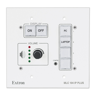
Page 14: Front Panel
Front Panel Front panel controls must be configured using the Global Configurator application (described in chapter 3) before they become functional. Display On/Off buttons — Use to turn the connected display device on and off. Input selection buttons — Use to select the desired audio and video input to the display device. -
Page 15: Right Side Panel
Right Side Panel Connectors on the unit's right side panel are described below. Display RS-232 / IR port — Dedicated bidirectional port for communication to a projector or display via RS-232 and/or infrared control. Comm Link — This port can be used to connect •... -
Page 16: Left Side Panel And Top Panel
Hardware Setup, cont’d Left Side Panel and Top Panel Controls on the left side panel and top panel are described below. Reset Button — Recessed button used to reset the device. See the MLC 104 Plus Series Reference Manual for available reset modes. -
Page 17: Power Connection
Power Connection To connect the external 12 VDC power supply: Strip the ends of the power supply wires as shown in the diagram below. Connect the stripped wires to the MLC's PWR port as shown in the diagram below. Connect the AC power cord between the power supply and an AC power outlet. -
Page 18: Lan Connection (Ip Models Only)
Hardware Setup, cont’d LAN Connection (IP Models Only) Connect a straight-through Ethernet cable to the LAN connector if you are connecting to a switch, hub, or router on your network. Connect a crossover Ethernet cable to the LAN connector if you are connecting directly to a PC. -
Page 19: Front Panel Host Configuration Port
Front Panel Host Configuration Port A 2.5 mm mini stereo jack the provides an RS-232 connection for configuration and control. Use Extron configuration cable part #70-335-01 (9-pin D female to 2.5 mm TRS) to connect a control PC to this port. VOLUME Front Panel The MLC 104 Plus (units without a LAN connection) can... -
Page 20: Device Connections
Hardware Setup, cont’d Device Connections The following illustrations show examples of A/V and control device connections for all models. Display connection DISPLAY RS-232/IR MLC 104 Plus Series Right Side Panel Infrared (IR) connection DISPLAY RS-232/IR MLC 104 Plus Series Right Side Panel Digital I/O connection GROUND IR OUT... -
Page 21: Comm Link Connection
Ground ( ) & Drain Wire Control Module Communication SCP Communication When an SCP 104 is connected to one of these controllers, the SCP's DIP switch #4 must be in the ON (up) position. MLS connection A B C MLC/IR MLC 104 Plus Series •... - Page 22 Hardware Setup, cont’d MLC 104 Plus Series • Hardware Setup 2-10...
-
Page 23: Chapter Three • Software Setup
MLC 104 Plus Series Chapter Three Software Setup Creating a Global Configurator Project File Configuring a New Device Testing the GlobalViewer Pages ™... -
Page 24: Creating A Global Configurator Project File
Creating a Global Configurator Project File After you have installed Global Configurator (GC) software on your PC, follow the steps in this chapter to configure your devices. Step one: download device drivers Software drivers for your audio/video devices are available free from the Extron web site at www.extron.com. - Page 25 Click the Right Arrow (Subscribe) button. Repeat steps 3 through 5 for each type of device you plan to add to your audio/video network. Click the Download button. The Download Complete dialog box opens. Click the Close button. Click OK to return to the Start Options dialog box. MLC 104 Plus Series •...
-
Page 26: Step Two: Create A New Project
Software Setup, cont’d Step two: create a new project To create a new Global Configurator project file: Select Create a New Project. Click OK. The Project Settings dialog box opens. For IP models For IP models, enter the IP address of the first device you will add to your GC project file in the Next Assigned IP Address field. -
Page 27: For An Mlc 104 Plus (Non-Ip Model)
Click OK. The Add Device dialog box opens. For an MLC 104 Plus (non-IP model) Click Cancel. The Add Device dialog box opens. MLC 104 Plus Series • Software Setup... -
Page 28: Step Three: Add A Device And Set Up Its Connection
Software Setup, cont’d Step three: add a device and set up its connection For IP models For IP models, obtain the following information from your network administrator: • IP address / hostname • gateway IP • subnet • Telnet port •... - Page 29 If the device you are adding is password protected, enter the appropriate Admin and User passwords. The default condition is no Admin or User password. Click Auto Configure IP Address. Enter the device’s MAC address (found on a label on the rear of the device).
-
Page 30: For An Mlc 104 Plus (Non-Ip Model)
Software Setup, cont’d For an MLC 104 Plus (non-IP model) Select MLC 104 Plus Series from the IP Link Device drop- down list. Click OK. MLC 104 Plus Series • Software Setup... -
Page 31: Step Four: Define The Location Of The New Device (Ip Models Only)
Step four: define the location of the new device (IP models only) Global Configurator allows you to keep track of the devices on your audio/video network by creating a custom tree of folders in which you can place and organize your audio/video devices. This GlobalViewer Tree can be up to eight levels deep and have multiple folders in each level. -
Page 32: Step Five: Save The New Global Configurator File
Software Setup, cont’d Step five: save the new Global Configurator file To save the new GC project file: Click File > Save - or - click the Save icon. If the file has not previously been saved, the Save As dialog box opens. -
Page 33: Configuring A New Device
Configuring a New Device Step six: configure e-mail server (IP models only) Obtain the following from your network administrator: • Mail server IP • Mail server domain • SMTP username and password Device must be online to change device settings. To set the e-mail server configuration: Click Tools >... -
Page 34: Step Seven: Configure E-Mail Messages (Ip Models Only)
Software Setup, cont’d Step seven: configure e-mail messages (IP models only) The Email Manager dialog box is used to create custom e-mails that are delivered as directed by the settings in the GC Schedule and Monitor dialog boxes. To create custom e-mails: Click Edit >... -
Page 35: Step Eight: Configure Contacts (Ip Models Only)
Step eight: configure contacts (IP models only) The Contact Manager dialog box is used to enter the name, e-mail address, and company name of the network’s contacts. To configure contacts: Click Edit > Contact Manager... Complete the Name, Email, and Company fields. Click Add. -
Page 36: Step Nine: Assign Serial Device Drivers
Software Setup, cont’d Step nine: assign serial device drivers The Serial Configuration tab of Global Configurator allows you to assign a device driver to each serial port of the device. To assign a device driver: Select a serial port in the IP Link Tree window. The Serial Configuration tab opens. -
Page 37: Step Ten: Assign Ir Drivers
Step ten: assign IR drivers The IR Configuration tab of Global Configurator allows you to assign a device driver to each IR port of the device. To assign an IR device driver: Select an IR port in the IP Link Tree window. The IR Configuration tab opens. -
Page 38: Step Eleven: Configure The Front Panel
Software Setup, cont’d Step eleven: configure the front panel The Front Panel tab provides a graphical representation of the MLC's front control panel. It gives you the ability to: • Configure the operations of the front control panel buttons • Configure the captions and functions of the control buttons that are displayed in the GlobalViewer interface. -
Page 39: Button Repeat Rate
Button repeat rate The repeat rate is how quickly a button will repeat its function if the button is held down. Example: If you have configured a button as an increment volume button, and given it a repeat rate of 1.00 second, as long as you keep this button pressed (the front panel button or the GlobalViewer button) the “increment volume”... -
Page 40: Button Modes
MLC's front panel. Button modes of operation are: • Single Switch — the pushbutton switch performs the same function each time it is pressed. • Toggle — you can assign two different actions to subsequent depressions of the same pushbutton. -
Page 41: Switcher Input
Switcher input The Switcher Input field allows you to assign a specific input from an attached MediaLink Switcher (MLS) to a specific input button on the MLC’s front panel (only applies to a button in input mode). To assign a switcher input: Select one of the four input buttons. -
Page 42: Button Operations
Software Setup, cont’d Button operations Selected functions in the Button Operations area of the window are moved to the Press, or Release windows to be assigned to the press or release action of the selected button. Tabs in the Button Operations area include: •... - Page 43 When you add multiple functions to a front panel button, you may want to insert a time delay between the functions. The Button Operations Time Delay tab provides the capability to add a delay of from 1 second to 180 seconds to the press or release action of a button.
- Page 44 Software Setup, cont’d The Button Operations User Defined tab allows users to add button functionality that is not predefined by entering ASCII strings or Extron Simple Instruction Set (SIS the Command field and moving those commands to the Press window or the Release window. The User Defined tab is only functional with serial ports.
- Page 45 Press and Release actions of selected buttons. Color changes are reflected on both the physical front panel button and the virtual front panel button in the GlobalViewer interface (only applies to buttons in single switch ® or group mode). Indicator color options are: •...
-
Page 46: Clear, Reset, And Auto Fill Captions
Software Setup, cont’d Clear, reset, and auto fill captions Use the Clear button to clear all front panel button caption text. Use the Reset button to delete all operations on the front panel buttons and reset the captions to their factory default text. The Auto Fill button is not active on the front panel tab. -
Page 47: Step Twelve: Configure Associated Control Modules
Step twelve: configure associated control modules A control module is a faceplate with buttons that can be associated with the MLC. The buttons on a control module can be configured to perform specific device operations, such as power on a device or raise/ lower audio volume. - Page 48 Software Setup, cont’d Select an available control module. Click the Add (right arrow, ) button. The new control module is displayed in the Control Module Summary field and in the IP Link Tree window. Select the newly assigned control module's Address in the IP Link Tree window.
-
Page 49: Step Thirteen: Create A Shutdown Schedule
Step thirteen: create a shutdown schedule Global Configurator’s scheduling feature enables you to schedule specific actions to occur for a selected device. As an example, scheduling is useful to set network projectors to power off at the end of the day to prevent idle lamp usage. To set a display shutdown schedule: Click the Schedule tab. - Page 50 Software Setup, cont’d Enter a unique name in the Schedule Action Name field. Set the desired schedule times. Click Next. Select the desired Subject Port (device). Select the Available Option Power Control - Off. Click Apply Action. Click Done. MLC 104 Plus Series • Software Setup 3-28...
-
Page 51: Step Fourteen: Create A Lamp Hour Notification (Ip Models Only)
Step fourteen: create a lamp hour notification (IP models only) Global Configurator’s monitoring feature enables you to configure IP Link devices to monitor many parameters of their connected audio/visual devices. This feature can be used to monitor lamp usage hours and send an e-mail alert to the network administrator if a display’s lamp is nearing expiration. - Page 52 Software Setup, cont’d Select a subject port or device. Select Available Options Lamp Usage: Value. Select Is Greater or Equal in the Display: Lamp Usage Value field. Enter a number (hours) that is less than the lamp’s anticipated burn-out spec in the Lamp Usage Value field. Click Apply Condition.
-
Page 53: Step Fifteen: Create A Disconnect Notification (Ip Models Only)
Step fifteen: create a disconnect notification (IP models only) Global Configurator’s monitoring feature enables you to configure IP Link devices such as an MLC 104 IP Plus to monitor many parameters of their connected audio/visual devices. This feature can be used to monitor a display connection and send an alert e-mail to the administrator if a display is unexpectedly disconnected from the network. - Page 54 Software Setup, cont’d Select a subject port or device. Select Available Options Connection Status: Disconnected. Click Apply Condition. Click Next. Click Next a second time to add an e-mail notification. Select Email Messages Disconnect Notification. Select the desired contacts. Click Apply Email/Contacts. Click Done.
-
Page 55: Step Sixteen: Build The Global Configurator File
Step sixteen: build the Global Configurator file Before a Global Configurator (GC) file is active in the GlobalViewer interface, the GC file must be “built” and uploaded to a GlobalViewer host device. The “build” process compiles all of the configuration data you have entered into the GC file for each A/V network device. -
Page 56: Step Seventeen: Upload The Global Configurator File
Software Setup, cont’d Step seventeen: upload the Global Configurator file When the build process completes, the Upload dialog box opens. Click the Begin button. When the upload process completes, the Progress and Status fields are updated to indicate completion. For IP models only, click the Test GV System button to view the GlobalViewer host interface. -
Page 57: Step Eighteen: Launch Globalviewer (Ip Models Only)
Step eighteen: launch GlobalViewer (IP models only) GlobalViewer is a graphical user interface that is generated by Global Configurator (GC). When a GC file is built and uploaded to a GlobalViewer host device, you can launch the GlobalViewer interface by opening an Internet browser and entering the host device’s IP address in the browser's address field. -
Page 58: Testing The Globalviewer Pages
Software Setup, cont’d Testing the GlobalViewer pages Use the GlobalViewer graphical user interface (IP models only), the MLC’s front panel, and, if present, the buttons on an associated control module to test for proper operation of the MLC and any connected devices. More information on operation and testing of the MLC and its connected devices can found in the MLC 104 Plus Series User's Manual, part number 68-1443-01, which can be downloaded... - Page 59 Extron Electronics warrants this product against defects in materials and workmanship for a period of three years from the date of purchase. In the event of malfunction during the warranty period attributable directly to faulty workmanship and/or materials, Extron Electronics will, at its option, repair or replace said products or components, to whatever extent it shall deem necessary to restore said product to proper operating condition, provided that it is returned within the warranty period, with proof of purchase and description of malfunction to:...
- Page 60 Setup Guide Checklist Chapter 1: Install Global Configurator • Download from www.extron.com, or • Install from Extron Software Products CD Chapter 2: Make the MLC cable connections. Chapter 3: Configure MLC 104 Plus Series using Global Extron USA - West Extron USA - East Headquarters +800.633.9876...