Extron electronics MediaLink MLC 52 Series User Manual
Hide thumbs
Also See for MediaLink MLC 52 Series:
- User manual (124 pages) ,
- User manual (120 pages) ,
- Quick start manual (17 pages)

Related Manuals for Extron electronics MediaLink MLC 52 Series


Summary of Contents for Extron electronics MediaLink MLC 52 Series
- Page 1 User Guide MediaLink MLC 52 Series MediaLink Controllers ® 68-1079-01 Rev. F 02 13...
- Page 2 Safety Instructions Safety Instructions • English Chinese Simplified (简体中文) 警告: 产品上的这个标志意在警告用户该产品机壳内有暴露的危险 WARNING: This symbol, , when used on the product, is intended to alert the user of the presence of uninsulated dangerous voltage within 电压, 有触电危险。 the product’s enclosure that may present a risk of electric shock. 注...
- Page 3 (SM) , and Trademarks (TM) are the property of RGB Systems, Inc. or Extron Electronics: Registered Trademarks (®) AVTrac, Cable Cubby, CrossPoint, eBUS, EDID Manager, EDID Minder, Extron, Flat Field,GlobalViewer, Hideaway, Inline, IP Intercom, IP Link, Key Minder, LockIt, MediaLink, PoleVault, PURE3,...
- Page 4 Conventions Used in this Guide Notifications The following notifications are used in this guide: CAUTION: A caution indicates a situation that may result in minor injury. Attention indicates a situation that may damage or destroy the product or ATTENTION: associated equipment. NOTE: A note draws attention to important information.
-
Page 5: Table Of Contents
Contents Mounting the MLC 52 ........23 Introduction ........... 1 Preparing the Site ......... 23 About this Guide ..........1 Mounting the MLC to an Electrical Box ..24 About the MLC 52 Series MediaLink Mounting the MLC to a Decora Mounting Controllers ............ - Page 6 Serial Communication ........ 46 Configuration Ports ........... 46 Using the MLC 52/DVCM 50 Configuration Program ............46 Installing the Software from the DVD ..... 47 Downloading and Installing the Software from the Website ......... 48 Starting the Configuration Program ....49 Loading Extron Drivers ........
-
Page 7: Introduction
Introduction This section gives an overview of the MLC 52 User Guide and describes the Extron ® MLC 52 Series MediaLink Controllers and their features. Topics include: ® • About this Guide • About the MLC 52 Series MediaLink Controllers •... -
Page 8: Standard Features
European models • MLC 52 RS EU — European two-gang size. Controls the display device by either IR or RS-232. • MLC 52 RS EU VC — European two-gang size. Controls the display device by either IR or RS-232. This model has a volume control knob to control an amplifier such as an Extron MPA Mini Power Amplifier (purchased separately). -
Page 9: Options And Accessories
• Inactivity timer for display shutoff — Adjustable timer control provides automatic shutdown of the display device to conserve energy, prevent plasma burn-in, and extend projector lamp life. • Front panel security lockout — Front panel lockout (executive mode) can be implemented where the MLC 52 is installed in an unsecured environment and universal access is not desirable. -
Page 10: Device Drivers
Device Drivers In order for the MLC 52 to control a switcher, projector, or other display device via IR or RS-232 communication, it must have drivers loaded for the devices it will control. Drivers can be obtained in the following ways: •... - Page 11 Extron PC VGA with Audio SI 26X Ceiling Speakers Extron MPA 152 Mini Power Ampli er 4/ 8 IN G W IR U TE L/ M 50 m 10 V DVD/VCR Combo IN P L IS D IO S-video and Composite Video with Audio Audio Output...
-
Page 12: Installation And Configuration
Installation and Configuration This section describes the front, side, and rear panel features of the four MLC 52 models, and provides procedures for installing and configuring the controllers. Topics include: • Rear Panel and Cable Connections • Installation Steps • Replacing the Faceplate (US Models Only) Replacing Button Labels •... - Page 13 VOL/ MUTE + 10V MLC 52 RS MK MLC 52 RS MK VC Figure 4. MLC 52 RS MK and MLC 52 RS MK VC Rear Views MLC 52 RS EU MLC 52 RS EU VC Figure 5. MLC 52 RS EU and MLC 52 RS EU VC Rear Views IR Learner/Transmitter —...
-
Page 14: Installation Steps
Configuration switches — When set to On, these DIP switches place the MLC in IR learning or data transfer mode, or disable IR repeats. Switch 1: Enables IR learning. • Switch 2: Enables data transfer, such as cloning the current MLC configuration •... -
Page 15: Replacing The Faceplate (Us Models Only)
If you want to use a different faceplate from the one that is attached, remove the installed faceplate from the MLC, and replace it with the new one (see Replacing the Faceplate [US Models Only]). Attach cables to the rear of the MLC and to the display device as well as any optional devices such as the MPA Mini Power Amplifier, IR emitters, and IRL 20. -
Page 16: Replacing Button Labels
Figure 6_Remove screws 2 3 4 Figure 6. Screws to Remove from the MLC Faceplate Figure 7_New faceplate MLC 52 Standoff Faceplate Figure 7. Installing the MLC onto a New Faceplate Replacing Button Labels The button caps are prelabeled for your convenience. However, you can replace the labels with others that are included with the MLC, as follows: The button assembly consists of a clear lens cap, the button label, and a white diffuser (see... - Page 17 Locate the small corner notch on the lens cap, and slide the screwdriver between the lens cap and the diffuser (see in the illustration below). Using a rotating motion of the screwdriver, carefully pry the two pieces apart (see in figure 9). Plunger Base Diffuser...
-
Page 18: Wiring The Control Connector
Wiring the Control Connector The display and source control connector allows you to connect cables for IR devices, RS-232 devices (RS models only), and AC power to the MLC. The illustration below shows the MLC control connector pin assignments that are described on the following pages. -
Page 19: Wiring For Ir Control
FIG_Wiring for RS-232 F Transmit (Tx) To the Display or Projector RS-232 Port D Ground (Gnd) F E D C B A RS-232 Figure 11. Wiring for RS-232 Control (RS Models Only) Extron recommends using the CTL Series Comm-Link Control System Cable, available in lengths of 500 feet (150 m) (non-plenum only) and 1000 feet (300 m) (plenum and non-plenum) for this connection (see Recommended Cables... - Page 20 Wiring an IRL 20 The Extron IRL 20 is a hard wired IR signal receiver that can be used with the MLC 52 and an IR remote control. The IRL 20 receives a signal via its front panel (or an IR sensor) from the IR remote control, and outputs a modulated IR signal via an IR emitter.
-
Page 21: Wiring The Power Connector
Wiring the Power Connector The control connector also contains a power connector for the MLC 52. Connect the supplied external 12 VDC, 1 A power supply to this port to power the MLC as shown in the following diagram. The Extron PS 1210 (included) and other Extron power supplies can be used NOTE: with the MLC 52. - Page 22 To transmit configuration data via IR, both the transferring and the receiving MLCs must be removed from the wall, electrical box, or furniture, and both must be powered on. The MLC that is already configured can be powered by an external power supply, or it can share a power supply with the unit that will be configured.
- Page 23 The front panel buttons act as data transfer progress indicators. While data is being transferred, the buttons on both the transmitting and the receiving MLCs blink sequentially in clockwise order, starting with the On button in the upper-left corner (see figure 16). This cycle repeats until transfer is complete. DISPLAY DISPLAY VOLUME...
-
Page 24: Configuring Using Ir Learning
When the data transfer is complete, do either of the following: If you want to repeat the transfer process to configure another MLC 52, repeat • steps 2 and 3 for the unit that is to be configured. Press any button on the donor unit. -
Page 25: Removing Ir Commands From A Button
Hold the remote control of the display device between 4 and 14 inches (10 to 36 cm) away from the MLC and point it at the IR Transmit/Receive LEDs on the MLC. Within 5 seconds of pressing the MLC button (step 3), press the button on the remote control whose function you want the selected MLC button to learn. -
Page 26: Setting Up Button Macros Using Ir
Setting Up Button Macros Using IR Buttons function in either toggle mode or macro mode. By default, all the buttons (except the On and Off Display buttons) are in toggle mode. This means that each press of the button issues one command — the next in sequence of the four commands programmed to the button (each button can store up to four commands). -
Page 27: Setting Up An Mlc 52 Vc Model With An Extron Amplifier
Press the MLC button that will store the input selection IR codes. The button blinks for 5 seconds, during which time it is able to learn codes. On the rear panel, the first (bottom) IR learning LED starts flashing.) If a command is not entered within 5 seconds, the button and LED stop blinking, and you must press the button again to put it in back in learning mode. -
Page 28: Requirements For The Mlc 52 Vc
MLC RS EU VC with MPA Extron SI 3 PC with Surface-mount Audio Speakers Extron MPA 152 Mini Power Ampli er 4/ 8 IR IN C LA L/ M 50 m IN P 10 V LI ST D IO R AT DVD/VCR Combo S-video and Composite Video... -
Page 29: Configuring The Mlc 52 Ir Vc And Mlc 52 Rs Vc Vol Buttons
Figure 21_Wiring MLC VC and MPA VOL/ MUTE + 10V RS-232 or IR 2 3 4 Projector Control MLC 52 VC Series COMPUTER IN-1 VIDEO AV IN AUDIO COMPUTER IN-2 AUDIO AUDIO OUTPUT MPA 152 CLASS 2 WIRING DO NOT GROUND H/Cs /B-Y LISTED... -
Page 30: Mounting The Mlc To An Electrical Box
• The standard US MLC 52 model includes a one-gang black or white plastic faceplate, which can be installed on a standard one-gang US electrical box that is at least 1.75 inches deep. A mounting bracket (“mud ring”) is also included. •... -
Page 31: Mounting The Mlc To A Decora Mounting Bracket
Ground the MLC to the electrical box as follows: Attach the bare wire end of the provided grounding wire to the Gnd pin of the 6-pole captive screw connector on the MLC rear panel. Attach the other end of the grounding wire to a screw on the junction box. NOTE: Do not ground a product to both a separate earth ground and the circuit ground (via a connector pin). -
Page 32: Mounting The Mlc To A Wall Or Furniture
Figure_Mounting US MLC to Decora Wall Wall Mounting Bracket (Mud Ring) V I D MLC 52 Figure 22. Mounting an MLC 52 to a Decora Mounting Bracket Mounting the MLC to a Wall or Furniture With all cables attached to the MLC and power disconnected at the source, insert the MLC into the wall or furniture. -
Page 33: Operation
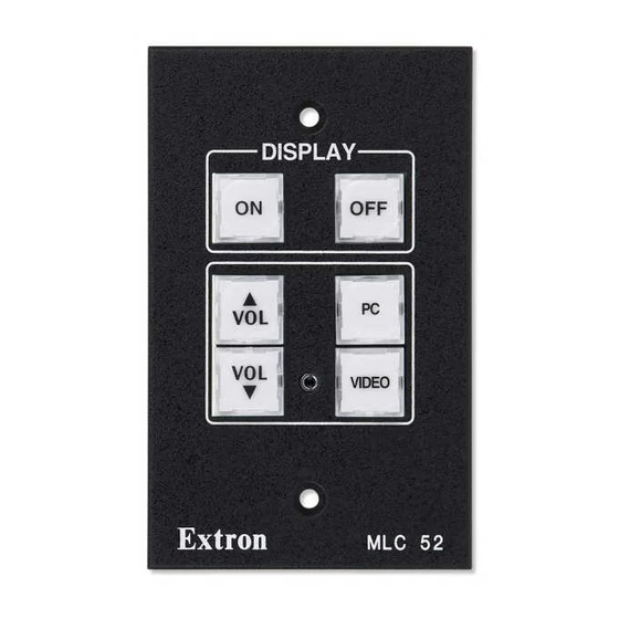
Operation This section describes the front panel features of the MLC 52 models and provides procedures for operating the controllers. Topics include: • Front Panel Features • Selecting Inputs • Resetting Locking the Front Panel (Executive Mode) • Front Panel Features The MLC 52 front panel contains six buttons, each of which can be programmed with up to four IR or RS-232 commands or functions. -
Page 34: Front Panel Components
Power mode: The two Display buttons at the top of the front panel, labeled On • and Off, are permanently in power mode. This mode is similar to input mode. The two Display buttons are mutually exclusive; if you press one, the other one becomes unlit. - Page 35 VOLUME VIDEO MLC 52 MLC 52 MLC 52 RS MK MLC 52 RS MK VC Figure 24. MLC 52 RS MK and MLC 52 RS MK VC Front Panels VIDEO VIDEO MLC 52 MLC 52 MLC 52 RS EU MLC 52 RS EU VC Figure 25.
- Page 36 Configuration port — Connect this port to your computer RS-232 port to configure and communicate with the MLC. Through this port, the MLC receives commands issued via the configuration software on your computer. Use a 2.5 mm TRS to 9-pin D-sub connector cable to connect the MLC to your PC via this 2.5 mm female TRS (tip-ring-sleeve) connector.
- Page 37 Selecting Inputs The four buttons below the On and Off buttons on the front panel can be configured to select inputs on the display device. The PC and Video buttons have been preconfigured to select inputs — a desktop or laptop computer (PC); a VCR or DVD (Video). Using IR learning, IR data transfer, or the MLC 52 configuration software, you can reconfigure these buttons and add commands to them to select other inputs if desired.
-
Page 38: Resetting
Resetting In the event that the MLC 52 needs to be reset, you can do so by one of the following methods: • Factory firmware reset — Press and hold the bottom right button (the Video button on standard models or the blank button on VC models) while applying power to the MLC. -
Page 39: Special Applications
Special Applications This section describes some special types of applications that represent unique conditions. For the MLC 52 to operate properly in these situations, it is important that the controller be configured correctly. In this section, three application examples are described, along with their requirements for the MLC 52. -
Page 40: Programming Buttons For An Ir Controlled System
The MLC 52 is configured differently depending on the type of projector remote control that will be used and on whether the MLC will use IR or RS-232 projector control. Because each button on the MLC 52 can store up to four commands per button, the PC and Video buttons should be programmed as shown in the illustrations below and on the following pages. - Page 41 Projector remote control type A (application 1) This remote control has a discrete button for each input. Two buttons are designated for RGB inputs, one for S-video, and one for video (composite). • Use IR learning to program the command from each of the projector remote control RGB input selection buttons onto the MLC PC button.
-
Page 42: Mlc 52 Vc
MLC 52 VC models with a type A remote control If you are using an MLC 52 IR VC or an MLC 52 RS VC model with a type A remote control, program the buttons using the following scheme: INPUTS RGB1 S-Video RGB2... -
Page 43: Programming Buttons For Multiple Inputs On An Rs-232 Controlled System
Standard MLC 52 with a type B remote control If you are using an MLC 52 IR or an MLC 52 RS with a type B remote control, program the buttons using the following scheme: COMPUTER VIDEO VIDEO AUDIO MUTE MUTE MUTE PROJECTOR... -
Page 44: Application 2: Controlling Projectors That Require Power Off Confirmation
Application 2: Controlling Projectors that Require Power Off Confirmation Some projectors controlled via IR require the Power Off button on the hand-held remote control to be pressed twice to turn off the projector. These projectors usually present a prompt (similar to the one shown below) on the image, instructing you to press the Power Off button again to confirm your intent to power off the projector. -
Page 45: Application 3: Controlling Projectors That Have Multi-Coded Ir Functionality
Put the MLC Off button that you have just programmed into macro mode by pressing and holding the button for 3 seconds. The orange LED on the back panel, labeled “E,” flashes rapidly five times, then turns off, indicating that the button is now configured for macro mode. - Page 46 Program the input selection command “A” from the RGB 2 input selection button on the projector remote control into memory block 2 of the MLC 52 PC button: Press the PC button on the MLC front panel. The button blinks, indicating that the MLC is ready to learn the command.
- Page 47 INPUTS S-Video RGB1 VIDEO RGB2 POWER PRG+ PLAY DISPLAY TIME/ TIME/ LEVEL– DLY/CNT/REAR LEVEL+ PAUSE LEFT RIGHT VOLUME STOP DOWN PRG– – SKIP/CHAPTER DIR A INPUT +100 Command 1: RGB 1 IR Command “A” Command 1: Video 1 IR Command “A” REC/ EFFECT PAUSE...
- Page 48 Program the input selection command “B” from the S-video input selection button on the projector remote control into memory block 4 of the MLC 52 Video or blank button as follows: Press the Video or blank button on the MLC front panel. The button blinks, indicating that the MLC is ready to learn the command.
-
Page 49: Configuration For A System With A Projector Remote Control Type B (Application 3)
Configuration for a System with a Projector Remote Control Type B (Application 3) A type B remote control has only two input buttons: one for the RGB inputs and one for 2 3 4 the S-video and composite video inputs (see page 34). - Page 50 COMPUTER VIDEO VIDEO AUDIO MUTE MUTE MUTE DISPLAY MENU ENTER VOLUME Command 1: Computer IR Command “A” Leave blank and do not program. The button should be in single switch mode. Command 2: Computer IR Command “B” CONT/ COL/ SIZE CENTER TINT Leave blank and do not program.
- Page 51 Issuing input selection commands learned from remote control type B The MLC now has two commands each on the PC and Video (or blank) buttons. When you press an MLC input button repeatedly, the following commands are issued: Using the PC button (RGB) •...
-
Page 52: Serial Communication
Serial Communication This section describes the procedure for accessing and starting the MLC 52/DVCM 50 Configuration Program and also contains a list and explanations of the Simple Instruction Set (SIS) commands available for the MLC 52. The following topics are covered: •... -
Page 53: Installing The Software From The Dvd
Installing the Software from the DVD To install the MLC 52 configuration software to your computer from the included Extron Software Products DVD: Insert the disc into your computer drive. The DVD should start automatically. If it does not, open your Windows Explorer and double-click on the DVD drive to Launch.exe start it. -
Page 54: Downloading And Installing The Software From The Website
Downloading and Installing the Software from the Website If you do not have the software on DVD, download it to your computer from the Extron website as follows: Visit the Extron website at www.extron.com and select the tab. Download Figure 43. Control Software Button on Download Center Screen On the Download Center screen, click the button. -
Page 55: Starting The Configuration Program
To run the configuration program: On your desktop, click > > > Start Extron Electronics MLC 52 DVCM 50 MLC 52 DVCM 50 Control Program On the Connection Window, select one of the two tabs: — This tab lets you establish a connection between your •... - Page 56 On the tab, select a COM port from the drop-down menu, Select a Comm Port On the tab, select one of the following radio buttons: Emulation Mode to create a new configuration in emulation mode • Start New Configuration to open an existing configuration. If you •...
-
Page 57: Loading Extron Drivers
Loading Extron Drivers Extron drivers are control files (libraries) of Extron-created projector or display commands that are specific to a particular display device. There are different sets of drivers for serial (RS-232) and for IR control. Before you can use the software to configure the MLC buttons, the IR, serial, or both driver packages must be loaded onto your computer. - Page 58 Downloading IR drivers from the DVD The software DVD provided with the MLC 52 contains a set of device drivers that are also available from the website. To load the drivers from the DVD to your computer: Load the Extron Software Products DVD into your CD or DVD drive. The disc should start automatically.
- Page 59 From the DVD, you can download either the current Extron driver package (containing all IR drivers that were available at the time the package was compiled) or one driver at a time. To download the driver package: Click Download install for current driver package (n.n MB) Figure 49.
- Page 60 To download a single driver: (Optional) From the Select Interface Type drop-down menu, select for the type of drivers to view. When you make this selection, only drivers in the current driver package are displayed. If you want to view all the IR drivers, including those outside the current package, click View All.
- Page 61 Downloading drivers from the website Drivers can also be obtained directly from the Extron website, as follows: Visit the Extron website at www.extron.com, and click the tab. Download Click the button (shown at right) on the Download Device Drivers Center screen. From the drop-down menu on the Device Drivers screen, select MLC 52 IR.
- Page 62 As you make each selection, the driver list below changes to display all available drivers meeting your selected criteria. Figure 52. Entering MLC 62 Driver Search Criteria Click on the device name whose driver you want to download. To download all the drivers in the current package, click the Download install for link.
-
Page 63: Using Sis Commands
The MLC sends the following copyright message only when it first powers on. (c) Copyright 20nn, Extron Electronics, MLC 52, Vn.nn, 60-100n-nn where Vn.nn is the firmware version number and 60-100 is the MLC 52 model number. -
Page 64: Symbol Definitions
Symbol Definitions ] = CR/LF (carriage return/line feed) (hex 0D 0A } = Soft carriage return (no line feed) (hex ; web | ) • = Space E = Escape key (hex ; web X! = Firmware version number (n.nn format) X@ = Display power status ( through = power off... -
Page 65: Command And Response Table For Sis Commands
Command and Response Table for SIS Commands ASCII Command Response Command Additional Description (Host to Unit) (Unit to Host) Information Requests Query firmware version Display firmware version two decimal places (n.nn). Example: 1.00 View controller part number Show the MLC 52 part number: 60-74n-nn MLC 52 IR = 60-744-02 MLC 52 RS = 60-744-12... -
Page 66: Reference Information
Reference Information This section contains the names and part numbers of included parts and optional accessories for all models of the MLC 52. It also contains instructions for mounting an electrical junction box and templates for measuring and cutting the hole in the mounting surface (US models only). -
Page 67: Optional Accessories
Optional Accessories These optional items can be ordered separately: Mounting Hardware Part Number EWB 101 one-gang external wall box (black, white) 60-1161-02, -03 JB 125 one-gang junction box, 2.5" (10 mm) deep 980130 SMB 101 one-gang surface mount box (black only) 60-1292-02 EWB 102 two-gang external wall box (black, white) 60-1162-02, -03... -
Page 68: Mounting An Electrical Box
Mounting an Electrical Box If you want to install the MLC 52 or MLC 52 VC (US models) in an electrical box (in a wall or in furniture), install the box as described below. NOTE: These instructions are for US models only. To mount an electrical box for an EU or MK model, follow the directions provided with the box by its manufacturer. -
Page 69: Templates For Mlc 52 And Mlc 52 Vc (Us Models)
1-gang wall box.eps Insert the electrical box into the opening, and attach it to the wall stud or furniture with nails or screws, leaving the front edge flush with the outer wall or furniture surface. The following illustration applies to all sizes of electrical boxes. Wall Stud Installation Cable... -
Page 70: Mlc 52 Ir And Mlc 52 Rs Cutout Template For The One-Gang Decora Mud Ring
MLC 52 IR and MLC 52 RS Cutout Template for the One-gang Decora Mud Ring To mount the MLC 52 to a one-gang plastic Decora mud ring, use the dimensions shown below to cut the hole in the mounting surface. Cut-Out Template for MLC 52 (Front View) -
Page 71: Mlc 52 Ir Vc And Mlc 52 Rs Vc Cutout Template For The Two-Gang Decora Mud Ring
MLC 52 IR VC and MLC 52 RS VC Cutout Template for the Two-gang Decora Mud Ring To mount the MLC 52 VC to a two-gang plastic Decora mud ring, use the dimensions shown below to cut the hole in the mounting surface. Cut-Out Template for MLC 52 VC (Front View) -
Page 72: Mlc 52 Ir And Mlc 52 Rs Cutout Template For Mounting Directly To A Wall Or Furniture
MLC 52 IR and MLC 52 RS Cutout Template for Mounting Directly to a Wall or Furniture To mount the MLC 52 RS or IR directly to a wall or furniture, use the dimensions shown below to cut the hole in the mounting surface. Cut-Out Template for MLC 52 (Front View) -
Page 73: Mlc 52 Ir Vc And Mlc 52 Rs Vc Cutout Template For Mounting Directly To A Wall Or Furniture
MLC 52 IR VC and MLC 52 RS VC Cutout Template for Mounting Directly to a Wall or Furniture To mount the MLC 52 RS VC or MLC 52 IR VC directly to a wall or furniture, use the dimensions shown below to cut the hole in the mounting surface. Cut-Out Template for MLC 52 VC (Front View) - Page 74 Extron Electronics makes no further warranties either expressed or implied with respect to the product and its quality, performance, merchantability, or fitness for any particular use. In no event will Extron Electronics be liable for direct, indirect, or consequential damages resulting from any defect in this product even if Extron Electronics has been advised of such damage.