Table of Contents
Advertisement
Quick Links
Advertisement
Table of Contents

Related Manuals for Extron electronics MLC 62 Series


Summary of Contents for Extron electronics MLC 62 Series
- Page 1 Setup Guide MLC 62 Series MediaLink Controllers ™ 68-1731-50 Rev. A 10 09...
- Page 2 Precautions Safety Instructions • English Warning Power sources • This equipment should be operated only from the power source This symbol is intended to alert the user of important indicated on the product. This equipment is intended to be used with a main power operating and maintenance (servicing) instructions in system with a grounded (neutral) conductor.
-
Page 3: Table Of Contents
Accessing MLC 62 EU side panel features......2-20 Chapter Three • Software Setup .......... 3-1 Installing the Configuration Software ........ 3-2 Downloading the software from the Web......3-2 Installing the software from the disk ........3-2 MLC 62 Series • Table of Contents... - Page 4 Resetting using the MLC 62 configuration software..3-11 Resetting using the Reset button........3-11 Accessing the Help File ............3-12 All trademarks mentioned in this manual are the properties of their respective owners. 68-1731-50..Rev. A 10.09 MLC 62 Series • Table of Contents...
-
Page 5: Chapter One • Introduction
MLC 62 Series Chapter One Introduction About.this.Manual About.the.MLC.62.MediaLink .Controllers ®... -
Page 6: About This Guide
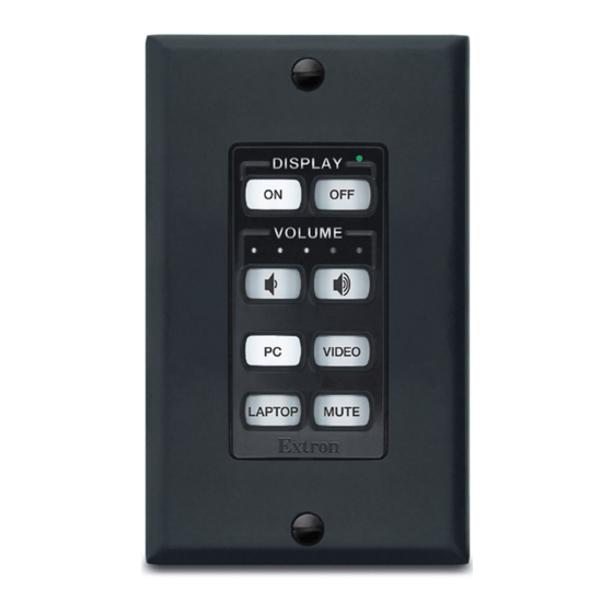
They act as extended remote control panels, telling the display when to switch between its various inputs. The MLC 62 series provide universal control for a display’s power, input switching, and volume control. For one-button functionality, the MLC 62 controllers feature eight labeled back-lit buttons. -
Page 7: Alternative Faceplates
The minimum system requirements for the PC on which you install the configuration software include: • Intel Pentium III 1 GHz processor ® ® • MicroSoft Windows XP SP2 • 512 MB of RAM • 50 MB of available hard disk space MLC 62 Series • Introduction... -
Page 8: Application Diagrams
Audio Output Extron IF IE ST ER M IN SI 3 IT E M ON L IM Screen Extron Extron Surface-Mount Control MPA 122 MLC 62 EU Speakers Mini Power MediaLink Controller ® Amplifier MLC 62 EU controlling a projector MLC 62 Series • Introduction... -
Page 9: Chapter Two • Hardware Setup
MLC 62 Series Chapter Two Hardware Setup UL.Safety.Requirements. Panels.and.Connectors Installation Accessing.the.Front.and.Side.Panels.after.Mounting... -
Page 10: Ul Safety Requirements
MLC 62 D or remove the entire MLC 62 EU from the wall. (See "Accessing Front and Side Panel Controls After Mounting", later in this chapter, for the removal procedures.) MLC 62 Series • Hardware Setup... -
Page 11: Button Illumination
When buttons are placed in a mode that groups them together (for example, Input mode) only the button that is pressed lights brightly. The other buttons in the group remain dim. (Refer to the configuration software's help file for information on setting button modes.) MLC 62 Series • Hardware Setup... -
Page 12: Front And Side Panel Features
When the power Off button is pressed, it blinks slowly while the display is cooling down. When this delay period has elapsed, the power button that was pressed lights brightly. MLC 62 Series • Hardware Setup... - Page 13 The IR-learned commands can be assigned or configured to be played back with any button press. Before performing IR learning, check to see if an Extron driver exists for your display device. The IR Learning feature will be supported in future releases. MLC 62 Series • Hardware Setup...
-
Page 14: Rear Panels
Digital Input port — This port provides an additional way to trigger functions on the MLC 62. Connect a switch to this 2-pole connector to initiate commands via the MLC to the display or other devices such as room lights or a motorized screen. MLC 62 Series • Hardware Setup... -
Page 15: Rear Panel Features On Mlc 62 Eu Only
It also blinks four times to indicate a successful reset. Reset button — Press this reset button to initiate factory or configuration resets. (See "Resetting the MLC" in chapter 3, "Software Setup", for more information.) DIP switches — Reserved for future use MLC 62 Series • Hardware Setup... -
Page 16: Installation
Configure the MLC's buttons and ports using the MLC 62 Windows-based Configuration Program. (See "Step 4: configure the front panel buttons" in chapter 3, "Software Setup." For detailed configuration procedures, refer to the software's help file.) When finished configuring, detach the USB cable. MLC 62 Series • Hardware Setup... -
Page 17: Removing And Replacing The Faceplate
(A matching Decora wallplate is also provided for each faceplate.) Faceplate replacement kits containing six-button or eight-button faceplates can be ordered. (Refer to appendix A, "Reference Information", in the MLC 62 User's Manual for information.) MLC 62 Series • Hardware Setup... -
Page 18: Removing And Replacing The Mlc 62 D Faceplate
MLC's main board. Press the faceplate onto the board with the pegs in the holes until the tabs at the top and bottom of the faceplate snap into their slots on the board. MLC 62 Series • Hardware Setup 2-10... -
Page 19: Removing And Replacing The Mlc 62 Eu Faceplate
MLC fit. Insert the flat head of the provided Extron Tweeker or another small screwdriver into one of the side slots. V I D Slot Removing the faceplate (MLC 62 EU) MLC 62 Series • Hardware Setup 2-11... -
Page 20: Replacing Buttons
From the front of the faceplate, press the button pair to be replaced backward through its slots in the faceplate until the membrane containing the two buttons is free. MLC 62 Series • Hardware Setup 2-12... -
Page 21: Wiring The Relays Port
Connect the ground wires of both devices to pin 3 of the provided 3-pin connector. Connect the signal wire of one device to pin 2 and the other to pin 1 of the 3-pin connector. MLC 62 Series • Hardware Setup 2-13... -
Page 22: Wiring The Ir/S Port
COMMON Rx pin on the output device. GROUND Tx/IR Ground ( ) Ground ( ) GROUND Transmit (Tx) Receive (Rx) GROUND +12 VDC Display Panel MLC 62 RS D Rear Panel Connecting a display to the RS-232 port of an MLC 62 RS D MLC 62 Series • Hardware Setup 2-14... -
Page 23: Connecting Power To The Mlc 62
Plug the connector into the rear panel PWR connector. GROUND Tx/IR GROUND Ground ( ) GROUND 12VDC input +12 VDC External MLC 62 RS D Ground all devices Power Supply Rear Panel (12 VDC) Connecting a power supply to an MLC 62 RS D MLC 62 Series • Hardware Setup 2-15... -
Page 24: Mounting The Mlc 62
Fasten the Decora wallplate onto the unit using two of the provided screws in the holes at the top and bottom. MLC 62 Series • Hardware Setup 2-16... - Page 25 MLC line up with the oval holes at the top and bottom of the bracket. Attach the MLC to the bracket using two of the provided screws in the holes at the top and bottom. MLC 62 Series • Hardware Setup 2-17...
-
Page 26: Mounting The Mlc 62 Eu
Mounting the MLC 62 EU The MLC 62 EU can be mounted to a one-gang EU electrical junction box. Electrical Junction Box Metal Bracket V I D Wall Frame MLC 62 RS EU Mounting the MLC 62 EU to an electrical junction MLC 62 Series • Hardware Setup 2-18... -
Page 27: Accessing The Front And Side Panels After Mounting
Reset button, and USB connector. To access these controls, unfasten the two screws at the top and bottom of the wallplate and lift it off the controller. (See the illustration on the next page.) MLC 62 Series • Hardware Setup 2-19... -
Page 28: Accessing Mlc 62 Eu Side Panel Features
MLC and the wall frame. Press the screwdriver head inward to release the tab holding the MLC in place in the wall frame. MLC 62 Series • Hardware Setup 2-20... - Page 29 Pry the MLC upward until it is free of the wall frame, then lift the unit out of the mounting surface. To reinstall the MLC, press it into the opening in the wall frame until the both tabs on the unit snap into place. MLC 62 Series • Hardware Setup 2-21...
- Page 30 Hardware Setup, cont’d MLC 62 Series • Hardware Setup 2-22...
-
Page 31: Chapter Three • Software Setup
MLC 62 Series Chapter Three Software Setup Installing.the.Configuration.Software Creating.a.New.MLC.62.Configuration Resetting.the.MLC Accessing.the.Help.File... -
Page 32: Installing The Configuration Software
On the Control Software screen, scroll to locate the MLC 62, and click the Install link in the far right column. Follow the instructions on the installation screens to complete the program installation. MLC 62 Series • Software Setup... -
Page 33: Creating A New Mlc 62 Configuration
Extron web site at www.extron.com. To download device drivers: Click Start > Programs > Extron Electronics > MLC 62 or double-click the MLC 62 software icon on your desktop to launch the MLC 62 software application. The MLC62 Configuration Program window opens, with the Start Options window displayed in front of it. -
Page 34: Step Two: Create A New Project
The Front Panel tab enables you to configure the buttons and assign all commands to them. MLC 62 Series • Software Setup... -
Page 35: Step Three: Configure The Ports
(ports are listed under the configuration's name). It is recommended that you start with the Display port. When you select the port, the Port Configuration screen is displayed. You can also click the Port Configuration tab to display it. MLC 62 Series • Software Setup... - Page 36 (for example, 3M, Sony, or Leica). c. From the Version menu, select either the Latest Version of the driver, or Any Version. In the Available Drivers window, select the driver for the device connected to the port. MLC 62 Series • Software Setup...
-
Page 37: Step Four: Configure The Front Panel Buttons
On and Off buttons, respectively. This is a common configuration that can be used to raise and lower a motorized screen that is connected to the Relay port. MLC 62 Series • Software Setup... - Page 38 On the Driver tab, click on the name of the command to be programmed onto the selected button. In the example above, the power On command was selected for the On button. MLC 62 Series • Software Setup...
-
Page 39: Step Five: Set Up Relays (Optional)
The procedure for assigning commands to the Digital Input port is similar to the process used to add commands to the front panel buttons. Refer to the MLC 62 configuration software's help file to configure this port. MLC 62 Series • Software Setup... -
Page 40: Step Seven: Upload The Configuration To The Mlc
When the window closes, the configuration has been uploaded to the connected device. Test the system to ensure that the MLC 62 controls it properly. MLC 62 Series • Software Setup 3-10... -
Page 41: Resetting Using The Mlc 62 Configuration Software
The Reset button remains lit while it is being held. DISPLAY RELAYS IR/ S RS-232 Reset Reset Button VOLUME Button MLC 62 RS EU rear panel MLC 62 D front panel VIDEO MUTE LAPTOP Extron MLC 62 Series • Software Setup 3-11... -
Page 42: Accessing The Help File
To open the help file, select Help file from the Help menu on the configuration software's main window. In this file, you can perform a search or use the table of contents to locate the topic or procedure you want. MLC 62 Series • Software Setup 3-12... - Page 43 In no event will Extron Electronics be liable for direct, indirect, or consequential damages resulting from any defect in this product even if Extron Electronics has been advised of such damage.
- Page 44 Inside USA / Canada Only Inside Europe Only Inside Asia Only Inside China Only Inside USA / Canada Only +1.919.863.1794 +31.33.453.4040 +65.6383.4400 +86.21.3760.1568 +1.714.491.1500 +1.919.863.1797 FAX +31.33.453.4050 FAX +65.6383.4664 FAX +86.21.3760.1566 FAX +1.714.491.1517 FAX © 2009 Extron Electronics. All rights reserved.