Table of Contents
Advertisement
Quick Links
Advertisement
Table of Contents

Related Manuals for Interlogix NS4702-24P-4S-4X


Summary of Contents for Interlogix NS4702-24P-4S-4X
- Page 1 NS4702-24P-4S-4X User Manual P/N 1072829 • REV 00.01 • ISS 14JUL14...
- Page 2 © 2014 United Technologies Corporation Copyright Interlogix is part of UTC Building & Industrial Systems,Inc. a unit of United Technologies Corporation. All rights reserved. The NS4702-24P-4S-4X name and logo are trademarks of United Technologies. Trademarks and patents Other trade names used in this document may be trademarks or registered trademarks of the manufacturers or vendors of the respective products.
-
Page 3: Table Of Contents
TABLE OF CONTENTS 1. INTRODUCTION........................10 1.1 Packet Contents ............................10 1.2 Product Description ...........................11 1.3 How to Use This Manual ..........................16 1.4 Product Features............................17 1.5 Product Specifications ..........................20 2. INSTALLATION ........................24 2.1 Hardware Description ..........................24 2.1.1 Switch Front Panel ..............................24 ... - Page 4 4.2.2 IP Configuration ..............................46 4.2.3 IP Status ................................48 4.2.4 Users Configuration .............................49 4.2.5 Privilege Levels ..............................52 4.2.6 NTP Configuration ...............................54 4.2.7 Time Configuration ..............................55 4.2.8 UPnP ...................................57 4.2.9 DHCP Relay ................................59 4.2.10 DHCP Relay Statistics ............................61 ...
- Page 5 4.4.1 Port Configuration..............................92 4.4.2 Port Statistics Overview ............................94 4.4.3 Port Statistics Detail.............................95 4.4.4 SFP Module Information ............................98 4.4.5 Port Mirror................................100 4.5 Link Aggregation ............................102 4.5.1 Static Aggregation..............................105 4.5.2 LACP Configuration ............................107 4.5.3 LACP System Status ............................109 ...
- Page 6 4.8 Multicast ..............................163 4.8.1 IGMP Snooping ..............................163 4.8.2 Profile Table...............................168 4.8.3 Address Entry ..............................169 4.8.4 IGMP Snooping Configuration ...........................171 4.8.5 IGMP Snooping VLAN Configuration.........................173 4.8.6 IGMP Snooping Port Group Filtering .........................175 4.8.7 IGMP Snooping Status ............................176 ...
- Page 7 4.9.15 WRED................................224 4.9.14 QoS Statistics ..............................227 4.9.15 Voice VLAN Configuration ..........................228 4.9.16 Voice VLAN OUI Table.............................232 4.10 Access Control Lists..........................234 4.10.1 Access Control List Status ..........................234 4.10.2 Access Control List Configuration........................236 4.10.3 ACE Configuration ............................238 ...
- Page 8 4.13 Address Table ............................324 4.13.1 MAC Table Configuration..........................324 4.13.2 MAC Address Table Status ..........................326 4.13.3 Dynamic ARP Inspection Table........................327 4.13.4 Dynamic IP Source Guard Table........................328 4.14 LLDP ................................331 4.14.1 Link Layer Discovery Protocol .........................331 ...
- Page 9 4.18.4 RMON Event Status............................383 4.18.5 RMON History Configuration ...........................384 4.18.6 RMON History Status............................386 4.18.7 RMON Statistics Configuration ........................387 4.18.8 RMON Statistics Status............................388 4.19 Ring................................390 4.19.1 MEP Configuration............................392 4.19.2 Detailed MEP Configuration ..........................394 4.19.3 Ethernet Ring Protocol Switch .........................397 ...
-
Page 10: Introduction
1. INTRODUCTION NS4702-24P-4S-4X is a 24-Port 10/100/1000Mbps 802.3at PoE + 4-Port 10G SFP+ Managed Switch with Hardware Layer3 IPv4/IPv6 Static Routing, NS4702-24P-4S-4X, comes with the multi-port Gigabit Ethernet Switch and SFP fiber optic connectibility and robust layer 2 features. The description of this model is shown below: 24-Port 10/100/1000Mbps 802.3at PoE +, 4 Shared Gigabit Ports (RJ45 and SFP) and 4-Port 10G SFP+... -
Page 11: Product Description
Cost-effective 10Gbps Uplink Capacitated Managed High Power PoE Switch for Large Surveillance Applications The NS4702 is the latest generation of Interlogix Managed Gigabit PoE Switches featuring Interlogix intelligent PoE functions to improve the availability of critical business applications. It provides IPv6/IPv4 Layer 3 static routing and built-in L2/L4 Gigabit Switching engine along with 24 10/100/1000Base-T ports featuring 30-watt 802.3at PoE+, 4 Gigabit SFP fiber slots and 4 10Gbps... - Page 12 Intelligent Powered Device Alive Check The NS4702 can be configured to monitor connected PD (Powered Device) status in real-time via ping action. Once the PD stops working and it is without response, the NS4702 will resume the PoE port power and bring the PD back to work. It will greatly enhance the network reliability through the PoE port resetting the PD’s power source and reduce administrator management burden.
- Page 13 PoE Schedule for Energy Saving Besides being used for IP surveillance, theNS4702 is certainly applicable to construct any PoE network including VoIP and wireless LAN. Under the trend of energy saving worldwide and contributing to the environmental protection on the Earth, the NS4702 can effectively control the power supply besides its capability of giving high watts power.
- Page 14 IPv4 and IPv6 VLAN Routing for Secure and Flexible Management To help customers stay on top of their businesses, the NS4702 switch not only provides ultra high transmission performance and excellent layer 2 technologies, but also offers IPv4/IPv6 VLAN routing feature which allows to cross over different VLANs and different IP addresses for the purpose of having a highly secured, flexible management and simpler networking application.
- Page 15 Intelligent SFP Diagnosis Mechanism The NS4702 supports SFP-DDM (Digital Diagnostic Monitor) function that greatly helps network administrator to easily monitor real-time parameters of the SFP, such as optical output power, optical input power, temperature, laser bias current, and transceiver supply voltage.
-
Page 16: How To Use This Manual
1.3 How to Use This Manual This User’s Manual is structured as follows: Section 2, INSTALLATION The section explains the functions of the Managed Switch and how to physically install the Managed Switch. Section 3, SWITCH MANAGEMENT The section contains the information about the software function of the Managed Switch. Section 4, WEB CONFIGURATION The section explains how to manage the Managed Switch by Web interface. -
Page 17: Product Features
1.4 Product Features Physical Port 24-Port 10/100/1000Base-T RJ-45 copper with IEEE 802.3at / 802.3af Power over Ethernet Injector function 4 100/1000Base-X mini-GBIC/SFP slot, shared with Port-21 to Port-24 compatible with 100Base-FX SFP 4 10GBase-SR/LR SFP+ slot, compatible with 1000Base-SX/LX/BX SFP ... - Page 18 Supports Spanning Tree Protocol STP, IEEE 802.1D Spanning Tree Protocol RSTP, IEEE 802.1w Rapid Spanning Tree Protocol MSTP, IEEE 802.1s Multiple Spanning Tree Protocol, spanning tree by VLAN BPDU Guard Supports Link Aggregation 802.3ad Link Aggregation Control Protocol (LACP) ...
- Page 19 Reset button for system reboot or reset to factory default SMTP / Syslog / SNMP Trap remote alarm System Log Interlogix Smart Discovery Utility for deploy management Redundant Data Protection ITU-T G.8032 Ethernet Ring Protection Switching...
-
Page 20: Product Specifications
1.5 Product Specifications NS4702-24P-4S-4X Product Hardware Specifications 24 10/100/1000Base-T RJ-45 auto-MDI/MDI-X ports Copper Ports 4 100/1000Base-X SFP interfaces, shared with Port-21 to Port-24 SFP/mini-GBIC Slots Compatible with 100Base-FX SFP transceiver 4 10GBase-SR/LR SFP+ interface (Port-25 to Port-28) SFP+ Slots Compatible with 1000Base-SX/LX/BX SFP transceiver... - Page 21 24 units PD @ 7 watts PoE Ability 24 units PD @ 15.4 watts 14 units PD @ 30.8 watts Layer 2 Functions Port disable / enable Auto-negotiation 10/100/1000Mbps full and half duplex mode selection Port Configuration Flow control disable / enable Display each port’s speed duplex mode, link status, flow control status, Port Status auto-negotiation status, trunk status...
- Page 22 Secure Management SSH, SSL, SNMP v3 Interfaces RFC-1213 MIB-II RFC-1493 Bridge MIB RFC-1643 Ethernet MIB RFC-2863 Interface MIB RFC-2665 Ether-Like MIB RFC-2819 RMON MIB (Group 1, 2, 3 and 9) RFC-2737 Entity MIB RFC-2618 RADIUS Client MIB SNMP MIBs RFC-2863 IF-MIB RFC-2933 IGMP-STD-MIB RFC-3411 SNMP-Frameworks-MIB RFC-4292 IP Forward MIB...
- Page 23 Temperature: -10 ~ 70 degrees C Storage Relative Humidity: 5 ~ 95% (non-condensing)
-
Page 24: Installation
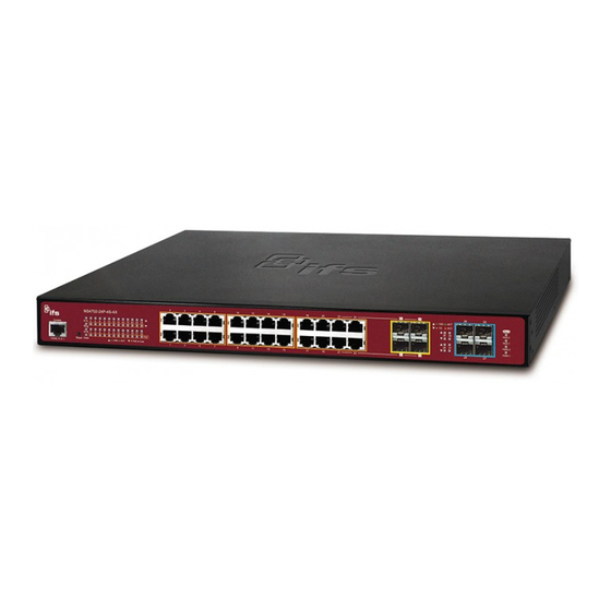
Figure 2-1-1 shows the front panel of the Managed Switch. NS4702-24P-4S-4X Front Panel Figure 2-1-1: Front Panels of NS4702-24P-4S-4X ■ Gigabit TP interface 10/100/1000Base-T Copper, RJ-45 Twist-Pair: Up to 100 meters. ■ SFP slot 100/1000Base-X mini-GBIC slot, SFP (Small Factor Pluggable) transceiver module: From 550 meters to 2km (multi-mode fiber), up to above 10/20/30/40/50/70/120 kilometers (single-mode fiber). -
Page 25: Led Indications
The front panel LEDs indicate instant status of power and system status, fan status, port links / PoE in-use and data activity; they help monitor and troubleshoot when needed. Figure 2-1-2 shows the LED indications of the Managed Switch. NS4702-24P-4S-4X LED Indication Figure 2-1-2: NS4702-24P-4S-4X LED at Front Panel NS4702-24P-4S-4X LED Indication Table LED definition System... - Page 26 Indicates that ring state is in idle. Lights Green Ring Indicates that ring state is in protected. Blink Indicates that the switch is set to ring owner. Lights Green R.O. Indicates that the switch doesn’t set to ring owner. Alert Color Function...
-
Page 27: Switch Rear Panel
Figure 2-1-3 shows the rear panel of the Managed Switch. NS4702-24P-4S-4X Rear Panel Figure 2-1-3: Rear Panel of NS4702-24P-4S-4X ■ AC Power Receptacle For compatibility with electric service in most areas of the world, the Managed Switch’s power supply automatically adjusts line power in the range of 100-240V AC and 50/60 Hz. -
Page 28: Installing The Switch
2.2 Installing the Switch This section describes how to install your Managed Switch and make connections to the Managed Switch. Please read the following topics and perform the procedures in the order being presented. To install your Managed Switch on a desktop or shelf, simply complete the following steps. -
Page 29: Rack Mounting
Connection to the Managed Switch requires UTP Category 5e network cabling with RJ-45 tips. For more information, please see the Cabling Specification in Appendix A. Supply power to the Managed Switch. Step 5: Connect one end of the power cable to the Managed Switch. Connect the power plug of the power cable to a standard wall outlet. -
Page 30: Installing The Sfp/Sfp+ Transceiver
Figure 2-2-3: Mounting Managed Switch in a Rack Proceed with Steps 4 and 5 of session 2.2.1 Desktop Installation to connect the network cabling and supply power to the Step 6: Managed Switch. 2.2.3 Installing the SFP/SFP+ Transceiver The sections describe how to insert an SFP/SFP+ transceiver into an SFP/SFP+ slot. The SFP/SFP+ transceivers are hot-pluggable and hot-swappable. - Page 31 Approved Interlogix SFP/SFP+ Transceivers Interlogix Managed Switch supports both single mode and multi-mode SFP/SFP+ transceiver. The following list of approved Interlogix SFP/SFP+ transceivers is correct at the time of publication: Fast Ethernet Transceiver (100Base-X SFP) SFP-Port 100Base-FX Transceiver (1310nm) - 2KM 0~50•C...
- Page 32 3. Port 25 to Port 28 are a shared SFP+ slot that supports the 10 Gigabit SFP+ transceiver and Gigabit SFP transceiver. Before we connect the NS4702-24P-4S-4X to the other network device, we have to make sure both sides of the SFP transceivers are with the same media type, for example: 1000Base-SX to 1000Base-SX, 1000Bas-LX to 1000Base-LX.
- Page 33 Remove the Transceiver Module Make sure there is no network activity anymore. Remove the Fiber-Optic Cable gently. Lift up the lever of the MGB module and turn it to a horizontal position. Pull out the module gently through the lever. Figure 2-2-5: How to Pull Out the SFP/SFP+ Transceiver Never pull out the module without lifting up the lever of the module and turning it to a horizontal position.
-
Page 34: Switch Management
3. SWITCH MANAGEMENT This chapter explains the methods that you can use to configure management access to the Managed Switch. It describes the types of management applications and the communication and management protocols that deliver data between your management device (workstation or personal computer) and the system. It also contains information about port connection options. This chapter covers the following topics: ... -
Page 35: Management Access Overview
3.2 Management Access Overview The Managed Switch gives you the flexibility to access and manage it using any or all of the following methods: An administration console Web browser interface An external SNMP-based network management application The administration console and Web browser interface support are embedded in the Managed Switch software and are available for immediate use. -
Page 36: Administration Console
3.3 Administration Console The administration console is an internal, character-oriented, and command line user interface for performing system administration such as displaying statistics or changing option settings. Using this method, you can view the administration console from a terminal, personal computer, Apple Macintosh, or workstation connected to the Managed Switch's console (serial) port. Figure 3-1-1: Console Management Direct Access Direct access to the administration console is achieved by directly connecting a terminal or a PC equipped with a terminal-emulation... -
Page 37: Web Management
connected and monitor the system during system reboots. Also, certain error messages are sent to the serial port, regardless of the interface through which the associated action was initiated. A Macintosh or PC attachment can use any terminal-emulation program for connecting to the terminal serial port. A workstation attachment under UNIX can use an emulator such as TIP. 3.4 Web Management The Managed Switch offers management features that allow users to manage the Managed Switch from anywhere on the network through a standard browser such as Microsoft Internet Explorer. -
Page 38: Snmp-Based Network Management
3.5 SNMP-based Network Management You can use an external SNMP-based application to configure and manage the Managed Switch, such as SNMP Network Manager, HP Openview Network Node Management (NNM) or What’s Up Gold. This management method requires the SNMP agent on the switch and the SNMP Network Management Station to use the same community string. -
Page 39: Web Configuration
4. WEB CONFIGURATION This section introduces the configuration and functions of the Web-based management from Managed Switch. About Web-based Management The Managed Switch offers management features that allow users to manage the Managed Switch from anywhere on the network through a standard browser such as Microsoft Internet Explorer. The Web-based Management supports Internet Explorer 7.0. - Page 40 username/password you have changed via console) to login the main screen of Managed Switch. The login screen in Figure 4-1-2 appears. Figure 4-1-2: Login Screen Default User name: admin Default Password: admin After entering the username and password, the main screen appears as shown in Figure 4-1-3.
- Page 41 Now, you can use the Web management interface to continue the switch management or manage the Managed Switch by Web interface. The Switch Menu on the left of the web Page lets you access all the commands and statistics the Managed Switch provides.
-
Page 42: Main Web Page
4.1 Main Web Page The Managed Switch provides a Web-based browser interface for configuring and managing it. This interface allows you to access the Managed Switch using the Web browser of your choice. This chapter describes how to use the Managed Switch’s Web browser interface to configure and manage it. - Page 43 monitor network conditions. Via the Web-Management, the administrator can set up the Managed Switch by selecting the functions those listed in the Main Function. The screen in Figure 4-1-5 appears. Figure 4-1-5: Managed Switch Main Functions Menu...
-
Page 44: System
4.2 System Use the System menu items to display and configure basic administrative details of the Managed Switch. Under the System, the following topics are provided to configure and view the system information. This section has the following items: The Managed Switch system information is provided here. ■... -
Page 45: System Information
4.2.1 System Information The System Infomation Page provides information for the current device information. System Information Page helps a switch administrator to identify the hardware MAC address, software version and system uptime. The screen in Figure 4-2-1 appears. Figure 4-2-1: System Information Page Screenshot The Page includes the following fields: Object Description... -
Page 46: Ip Configuration
: Click to refresh the Page; any changes made locally will be undone. 4.2.2 IP Configuration The IP Configuration includes the IP Configuration, IP Interface and IP Routes. The configured column is used to view or change the IP configuration. The maximum number of interfaces supported is 128 and the maximum number of routes is 32. The screen in Figure 4-2-2 appears. - Page 47 No DNS server No DNS server will be used. Configured Explicitly provide the IP address of the DNS Server in dotted decimal notation. From this DHCP interface Specify from which DHCP-enabled interface a provided DNS server should be preferred. When DNS proxy is enabled, system will relay DNS requests to the DNS Proxy currently configured DNS server, and reply as a DNS resolver to the client...
-
Page 48: Ip Status
Buttons : Click to add a new IP interface. A maximum of 128 interfaces is supported. : Click to add a new IP route. A maximum of 32 routes is supported. : Click to apply changes. : Click to undo any changes made locally and revert to previously saved values. 4.2.3 IP Status IP Status displays the status of the IP protocol layer. -
Page 49: Users Configuration
The status flags of the interface (and/or address). Status IP Routes The destination IP network or host address of this route. Network The gateway address of this route. Gateway The status flags of the route. Status Neighbor Cache The IP address of the entry. - Page 50 Generally, the privilege level 15 can be used for an administrator account, privilege level 10 for a standard user account and privilege level 5 for a guest account. Buttons : Click to add a new user. Add / Edit User This Page configures a user –...
- Page 51 By default setting, most groups privilege level 5 has the read-only access and privilege level 10 has the read-write access. And the system maintenance (software upload, factory defaults and etc.) need user privilege level 15. Generally, the privilege level 15 can be used for an administrator account, privilege level 10 for a standard user account and privilege level 5 for a guest account.
-
Page 52: Privilege Levels
4.2.5 Privilege Levels This Page provides an overview of the privilege levels. After setup is completed, please press “Apply” button to take effect. Please login web interface with new user name and password and the screen in Figure 4-2-7 appears. Figure 4-2-7: Privilege Levels Configuration Page Screenshot... - Page 53 The Page includes the following fields: Object Description Group Name The name identifying the privilege group. In most cases, a privilege level group consists of a single module (e.g. LACP, RSTP or QoS), but a few of them contain more than one.
-
Page 54: Ntp Configuration
4.2.6 NTP Configuration Configure NTP on this Page. NTP is an acronym for Network Time Protocol, a network protocol for synchronizing the clocks of computer systems. NTP uses UDP (data grams) as transport layer. You can specify NTP Servers. The NTP Configuration screen in Figure 4-2-8 appears. -
Page 55: Time Configuration
4.2.7 Time Configuration Configure Time Zone on this Page. A Time Zone is a region that has a uniform standard time for legal, commercial, and social purposes. It is convenient for areas in close commercial or other communication to keep the same time, so time zones tend to follow the boundaries of countries and their subdivisions. - Page 56 to identify the time zone. ( Range : Up to 16 characters ) Daylight Saving Time This is used to set the clock forward or backward according to the configurations set below for a defined Daylight Saving Time duration. Select 'Disable' to disable the Daylight Saving Time configuration.
-
Page 57: Upnp
4.2.8 UPnP Configure UPnP on this Page. UPnP is an acronym for Universal Plug and Play. The goals of UPnP are to allow devices to connect seamlessly and to simplify the implementation of networks in the home (data sharing, communications, and entertainment) and in corporate environments for simplified installation of computer components. - Page 58 : Click to undo any changes made locally and revert to previously saved values. Figure 4-2-11: UPnP devices show on Windows My Network Place...
-
Page 59: Dhcp Relay
4.2.9 DHCP Relay Configure DHCP Relay on this Page. DHCP Relay is used to forward and to transfer DHCP messages between the clients and the server when they are not on the same subnet domain. The DHCP option 82 enables a DHCP relay agent to insert specific information into a DHCP request packets when forwarding client DHCP packets to a DHCP server and remove the specific information from a DHCP reply packets when forwarding server DHCP packets to a DHCP client. - Page 60 Relay Server Indicates the DHCP relay server IP address. A DHCP relay agent is used to forward and transfer DHCP messages between the clients and the server when they are not on the same subnet domain. Relay Information Indicates the DHCP relay information mode option operation.
-
Page 61: Dhcp Relay Statistics
4.2.10 DHCP Relay Statistics This Page provides statistics for DHCP relay. The DHCP Relay Statistics screen in Figure 4-2-13 appears. Figure 4-2-13: DHCP Relay Statistics Page Screenshot The Page includes the following fields: Server Statistics Object Description Transmit to Server The packets number that relayed from client to server. - Page 62 Client Statistics Object Description Transmit to Client The packets number that relayed packets from server to client. Transmit Error The packets number that erroneously sent packets to servers. Receive from Client The packets number that received packets from server. ...
-
Page 63: Cpu Load
4.2.11 CPU Load This Page displays the CPU load, using a SVG graph. The load is measured as average over the last 100ms, 1sec and 10 seconds intervals. The last 120 samles are graphed, and the last numbers are displayed as text as well. In order to display the SVG graph, your browser must support the SVG format. -
Page 64: System Log
4.2.12 System Log The Managed Switch system log information is provided here. The System Log screen in Figure 4-2-15 appears. Figure 4-2-15: System Log Page Screenshot The Page includes the following fields: Object Description ID The ID (>= 1) of the system log entry. ... - Page 65 Buttons Auto-refresh : Check this box to refresh the Page automatically. Automatic refresh occurs every 3 seconds. : Updates the system log entries, starting from the current entry ID. : Flushes the selected log entries. : Hides the selected log entries. : Downloads the selected log entries.
-
Page 66: Detailed Log
4.2.13 Detailed Log The Managed Switch system detailed log information is provided here. The Detailed Log screen in Figure 4-2-16 appears. Figure 4-2-15: Detailed Log Page Screenshot The Page includes the following fields: Object Description ID The ID (>= 1) of the system log entry. ... -
Page 67: Remote Syslog
4.2.14 Remote Syslog Configure remote syslog on this Page. The Remote Syslog screen in Figure 4-2-17 appears. Figure 4-2-17: Remote Syslog Page Screenshot The Page includes the following fields: Object Description Mode Indicates the server mode operation. When the mode operation is enabled, the syslog message will send out to syslog server. -
Page 68: Smtp Configuration
4.2.15 SMTP Configuration This Page facilitates an SMTP Configuration on the switch. The SMTP Configure screen in Figure 4-2-18 appears. Figure 4-2-18: SMTP Configuration Page Screenshot The Page includes the following fields: Object Description SMTP Mode Controls whether SMTP is enabled on this switch. ... -
Page 69: Web Firmware Upgrade
: Click to undo any changes made locally and revert to previously saved values. 4.2.16 Web Firmware Upgrade This Page facilitates an update of the firmware controlling the switch. The Web Firmware Upgrade screen in Figure 4-2-19 appears. Figure 4-2-19: Web Firmware Upgrade Page Screenshot To open Firmware Upgrade screen, perform the following: Click System ->... -
Page 70: Tftp Firmware Upgrade
Do not quit the Firmware Upgrade Page without pressing the “OK” button after the image is loaded. Or the system won’t apply the new firmware. User has to repeat the firmware upgrade processes. 4.2.17 TFTP Firmware Upgrade The Firmware Upgrade Page provides the functions to allow a user to update the Managed Switch firmware from the TFTP server in the network. -
Page 71: Save Startup Config
4.2.17 Save Startup Config This function allows save the current configuration, thereby ensuring that the current active configuration can be used at the next reboot screen in Figure 4-2-22 appears. After saving the configuratioin, the screen Figure 4-2-23 will appear. Figure 4-2-22: Configuration Save Page Screenshot Figure 4-2-23: Finish Saving Page Screenshot 4.2.18 Configuration Download... -
Page 72: Configuration Upload
Figure 4-2-24: Configuration Download Page Screenshot 4.2.20 Configuration Upload Configuration Upload page allows the upload the running-config and startup-config on the switch. Please refer to the Figure 4-2-25 shown below. Figure 4-2-25: Configuration Upload Page Screenshot If the destination is running-config, the file will be applied to the switch configuration. This can be done in two ways: ... -
Page 73: Configuration Activate
4.2.21 Configuration Activate Configuration Activate page allows to activate the startup-config and default-config files present on the switch. Please refer to the Figure 4-2-26 shown below. Figure 4-2-26: Configuration Activate Page Screenshot It is possible to activate any of the configuration files present on the switch, except for running-config which represents the currently active configuration. -
Page 74: Image Select
4.2.23 Image Select This Page provides information about the active and alternate (backup) firmware images in the device, and allows you to revert to the alternate image. The web Page displays two tables with information about the active and alternate firmware images. The Image Select screen in Figure 4-2-28 appears. -
Page 75: Factory Default
Buttons : Click to use the alternate image. This button may be disabled depending on system state. 4.2.24 Factory Default You can reset the configuration of the Managed Switch on this Page. Only the IP configuration is retained. The new configuration is available immediately, which means that no restart is necessary. -
Page 76: System Reboot
4.2.25 System Reboot The Reboot Page enables the device to be rebooted from a remote location. Once the Reboot button is pressed, user have to re-login the WEB interface about 60 seconds later, the System Reboot screen in Figure 4-2-30 appears. -
Page 77: Simple Network Management Protocol
4.3 Simple Network Management Protocol 4.3.1 SNMP Overview The Simple Network Management Protocol (SNMP) is an application layer protocol that facilitates the exchange of management information between network devices. It is part of the Transmission Control Protocol/Internet Protocol (TCP/IP) protocol suite. SNMP enables network administrators to manage network performance, find and solve network problems, and plan for network growth. - Page 78 SNMP community An SNMP community is the group that devices and management stations running SNMP belong to. It helps define where information is sent. The community name is used to identify the group. A SNMP device or agent may belong to more than one SNMP community. It will not respond to requests from management stations that do not belong to one of its communities.
-
Page 79: Snmp System Configuration
4.3.2 SNMP System Configuration Configure SNMP on this Page. The SNMP System Configuration screen in Figure 4-3-1 appears. Figure 4-3-1: SNMP System Configuration Page Screenshot The Page includes the following fields: Object Description Indicates the SNMP mode operation. Possible modes are: Mode ... - Page 80 SNMP version is SNMPv3, the community string will be associated with SNMPv3 communities table. It provides more flexibility to configure security name than a SNMPv1 or SNMPv2c community string. In addition to community string, a particular range of source addresses can be used to restrict source subnet. ...
-
Page 81: Snmp Trap Configuration
4.3.3 SNMP Trap Configuration Configure SNMP trap on this Page. The SNMP Trap Configuration screen in Figure 4-3-2 appears. Figure 4-3-2: SNMP Trap Configuration Page Screenshot The Page includes the following fields: Object Description Indicates which trap Configuration's name for configuring. The allowed string Trap Config length is 0 to 255, and the allowed content is ASCII characters from 33 to 126. - Page 82 Indicates the community access string when send SNMP trap packet. The Trap Community allowed string length is 0 to 255, and the allowed content is the ASCII characters from 33 to 126. Indicates the SNMP trap destination address. It allow a valid IP address in dotted Trap Destination decimal notation ('x.y.z.w').
- Page 83 System Enable/disable that the Interface group's traps. Possible traps are: Warm Start: Enable/disable Warm Start trap. Cold Start: Enable/disable Cold Start trap. Interface Indicates that the Interface group's traps. Possible traps are: Link Up: Enable/disable Link up trap. ...
-
Page 84: Snmp System Information
4.3.4 SNMP System Information The switch system information is provided here. The SNMP System Information screen in Figure 4-3-3 appears. Figure 4-3-3: System Information Configuration Page Screenshot The Page includes the following fields: Object Description The textual identification of the contact person for this managed node, together System Contact with information on how to contact this person. -
Page 85: Snmpv3 Configuration
4.3.5 SNMPv3 Configuration 4.3.5.1 SNMPv3 Communities Configure SNMPv3 communities table on this Page. The entry index key is Community. The SNMPv3 Communities screen in Figure 4-3-4 appears. Figure 4-3-4: SNMPv3 Communities Configuration Page Screenshot The Page includes the following fields: Object Description ... -
Page 86: Snmpv3 Users
4.3.5.2 SNMPv3 Users Configure SNMPv3 users table on this Page. The entry index keys are Engine ID and User Name. The SNMPv3 Users screen in Figure 4-3-5 appears. Figure 4-3-5: SNMPv3 Users Configuration Page Screenshot The Page includes the following fields: Object Description ... - Page 87 Indicates the authentication protocol that this entry should belong to. Possible Authentication authentication protocol are: Protocol None: None authentication protocol. MD5: An optional flag to indicate that this user using MD5 authentication protocol. SHA: An optional flag to indicate that this user using SHA authentication protocol.
-
Page 88: Snmpv3 Groups
4.3.5.3 SNMPv3 Groups Configure SNMPv3 groups table on this Page. The entry index keys are Security Model and Security Name. The SNMPv3 Groups screen in Figure 4-3-6 appears. Figure 4-3-6: SNMPv3 Groups Configuration Page Screenshot The Page includes the following fields: Object Description ... -
Page 89: Snmpv3 Views
4.3.5.4 SNMPv3 Views Configure SNMPv3 views table on this Page. The entry index keys are View Name and OID Subtree. The SNMPv3 Views screen in Figure 4-3-7 appears. Figure 4-3-7: SNMPv3 Views Configuration Page Screenshot The Page includes the following fields: Object Description ... -
Page 90: Snmpv3 Access
4.3.5.5 SNMPv3 Access Configure SNMPv3 accesses table on this Page. The entry index keys are Group Name, Security Model and Security Level. The SNMPv3 Access screen in Figure 4-3-8 appears. Figure 4-3-8: SNMPv3 Accesses Configuration Page Screenshot The Page includes the following fields: Object Description ... - Page 91 Buttons : Click to add a new access entry. : Click to apply changes : Click to undo any changes made locally and revert to previously saved values.
-
Page 92: Port Management
4.4 Port Management Use the Port Menu to display or configure the Managed Switch's ports. This section has the following items: Configures port connection settings Port Configuration Lists Ethernet and RMON port statistics Port Statistics Overview Lists Ethernet and RMON port statistics ... - Page 93 Port Description Indicates the per port description. The current link state is displayed graphically. Green indicates the link is up and Link red that it is down. Provides the current link speed of the port. Current Link Speed ...
-
Page 94: Port Statistics Overview
: Click to undo any changes made locally and revert to previously saved values. : Click to refresh the Page. Any changes made locally will be undone. 4.4.2 Port Statistics Overview This Page provides an overview of general traffic statistics for all switch ports. The Port Statistics Overview screen in Figure 4-4-2 appears. -
Page 95: Port Statistics Detail
Buttons : Download the Port Statistics Overview result as EXECL file. : Click to refresh the Page immediately. : Clears the counters for all ports. : Print the Port Statistics Overview result. Auto-refresh : Check this box to enable an automatic refresh of the Page at regular intervals. 4.4.3 Port Statistics Detail This Page provides detailed traffic statistics for a specific switch port. - Page 96 The Page includes the following fields: Receive Total and Transmit Total Object Description The number of received and transmitted (good and bad) packets Rx and Tx Packets The number of received and transmitted (good and bad) bytes, including FCS, Rx and Tx Octets but excluding framing bits.
- Page 97 1 Short frames are frames that are smaller than 64 bytes. 2 Long frames are frames that are longer than the configured maximum frame length for this port. Transmit Error Counters Object Description The number of frames dropped due to output buffer congestion. Tx Drops ...
-
Page 98: Sfp Module Information
4.4.4 SFP Module Information The WGSW-48040HP has supported the SFP module with digital diagnostics monitoring (DDM) function, this feature is also known as digital optical monitoring (DOM). You can check the physical or operational status of an SFP module via the SFP Module Information Page. - Page 99 Temperature(C) Display the temperature of current SFP DDM module, the temperature value is get from the SFP DDM module. – SFP DDM Module Only Voltage(V) Display the voltage of current SFP DDM module, the voltage value is get from the SFP DDM module.
-
Page 100: Port Mirror
4.4.5 Port Mirror Configure port Mirroring on this Page. This function provide to monitoring network traffic that forwards a copy of each incoming or outgoing packet from one port of a network Switch to another port where the packet can be studied. It enables the manager to keep close track of switch performance and alter it if necessary. - Page 101 Mirror Port Configuration The Port Mirror screen in Figure 4-4-8 appears. Figure 4-4-8: Mirror Configuration Page Screenshot The Page includes the following fields: Object Description Port to mirror on Frames from ports that have either source (rx) or destination (tx) mirroring enabled are mirrored to this port.
-
Page 102: Link Aggregation
Both: Frames received and frames transmitted are mirrored to the mirror port. ■ For a given port, a frame is only transmitted once. It is therefore not possible to mirror Tx frames on the mirror port. Because of this, mode for the selected mirror port is limited to Disabled or Rx only. Buttons : Click to apply changes : Click to undo any changes made locally and revert to previously saved values. - Page 103 Figure 4-5-1: Link Aggregation The Link Aggregation Control Protocol (LACP) provides a standardized means for exchanging information between Partner Systems that require high speed redundant links. Link aggregation lets you group up to eight consecutive ports into a single dedicated connection. This feature can expand bandwidth to a device on the network. LACP operation requires full-duplex mode, more detail information refer to the IEEE 802.3ad standard.
- Page 104 It allows a maximum of 10 ports to be aggregated at the same time. The Managed Switch support Gigabit Ethernet ports (up to 5 groups). If the group is defined as a LACP static link aggregationing group, then any extra ports selected are placed in a standby mode for redundancy if one of the other ports fails.
-
Page 105: Static Aggregation
4.5.1 Static Aggregation This Page is used to configure the Aggregation hash mode and the aggregation group. The aggregation hash mode settings are global, whereas the aggregation group relate to the currently selected stack unit, as reflected by the Page header. Hash Code Contributors The Static Aggeration screen in Figure 4-5-2... - Page 106 Static Aggregation Group Configuration The Aggregation Group Configuration screen in Figure 4-5-3 appears. Figure 4-5-3: Aggregation Group Configuration Page Screenshot The Page includes the following fields: .Object Description Indicates the group ID for the settings contained in the same row. Group ID Group ID "Normal"...
-
Page 107: Lacp Configuration
4.5.2 LACP Configuration Link Aggregation Control Protocol (LACP) - LACP LAG negotiate Aggregated Port links with other LACP ports located on a different device. LACP allows switches connected to each other to discover automatically whether any ports are member of the same LAG. This Page allows the user to inspect the current LACP port configurations, and possibly change them as well. - Page 108 The Page includes the following fields: Object Description The switch port number. Port Controls whether LACP is enabled on this switch port. LACP will form an LACP Enabled aggregation when 2 or more ports are connected to the same partner. LACP can form max 12 LAGs per switch and 2G LAGs per stack.
-
Page 109: Lacp System Status
4.5.3 LACP System Status This Page provides a status overview for all LACP instances. The LACP Status Page display the current LACP aggregation Groups and LACP Port status. The LACP System Status screen in Figure 4-5-5 appears. Figure 4-5-5: LACP System Status Page Screenshot The Page includes the following fields: Object Description... -
Page 110: Lacp Port Status
4.5.4 LACP Port Status This Page provides a status overview for LACP status for all ports. The LACP Port Status screen in Figure 4-5-6 appears. Figure 4-5-6: LACP Status Page Screenshot The Page includes the following fields: Object Description The switch port number. -
Page 111: Lacp Port Statistics
Buttons : Click to refresh the Page immediately. Auto-refresh : Automatic refresh occurs every 3 seconds. 4.5.5 LACP Port Statistics This Page provides an overview for LACP statistics for all ports. The LACP Port Statistics screen in Figure 4-5-7 appears. Figure 4-5-7: LACP Statistics Page Screenshot The Page includes the following fields: Object... - Page 112 Buttons Auto-refresh : Automatic refresh occurs every 3 seconds. : Click to refresh the Page immediately. : Clears the counters for all ports.
-
Page 113: Vlan
4.6 VLAN 4.6.1 VLAN Overview A Virtual Local Area Network (VLAN) is a network topology configured according to a logical scheme rather than the physical layout. VLAN can be used to combine any collection of LAN segments into an autonomous user group that appears as a single LAN. VLAN also logically segment the network into different broadcast domains so that packets are forwarded only between ports within the VLAN. -
Page 114: Ieee 802.1Q Vlan
4.6.2 IEEE 802.1Q VLAN In large networks, routers are used to isolate broadcast traffic for each subnet into separate domains. This Managed Switch provides a similar service at Layer 2 by using VLANs to organize any group of network nodes into separate broadcast domains. VLANs confine broadcast traffic to the originating group, and can eliminate broadcast storms in large networks. -
Page 115: Q Vlan Tags
allows Spanning Tree to be enabled on all ports and work normally. Some relevant terms: Tagging - The act of putting 802.1Q VLAN information into the header of a packet. Untagging - The act of stripping 802.1Q VLAN information out of the packet header. ■... -
Page 116: Port Vlan Id
■ Port VLAN ID Packets that are tagged (are carrying the 802.1Q VID information) can be transmitted from one 802.1Q compliant network device to another with the VLAN information intact. This allows 802.1Q VLAN to span network devices (and indeed, the entire network – if all network devices are 802.1Q compliant). -
Page 117: Vlan Port Configuration
■ VLAN Classification When the switch receives a frame, it classifies the frame in one of two ways. If the frame is untagged, the switch assigns the frame to an associated VLAN (based on the default VLAN ID of the receiving port). But if the frame is tagged, the switch uses the tagged VLAN ID to identify the port broadcast domain of the frame. - Page 118 information. (Remember that the PVID is only used internally within the Switch). Untagging is used to send packets from an 802.1Q-compliant network device to a non-compliant network device. Frame Income Income Frame is tagged Income Frame is untagged Frame Leave Leave port is tagged Frame remains tagged Tag is inserted...
- Page 119 provider bridge is to recognize and use VLAN tags so that the VLANs in the MAN space can be used independent of the customers’ VLANs. This is accomplished by adding a VLAN tag with a MAN-related VID for frames entering the MAN. When leaving the MAN, the tag is stripped and the original VLAN tag with the customer-related VID is again available.
- Page 120 Port VLAN Configuration The VLAN Port Configuration screen in Figure 4-6-2 appears. Figure 4-6-2 : Port VLAN Configuration Screenshot The Page includes the following fields: Object Description This is the logical port number for this row. Port Mode Access ports are normally used to connect to end stations.
- Page 121 The VLANs that a trunk port is member of may be limited by the use of Allowed VLANs Frames classified to a VLAN that the port is not a member of are discarded By default, all frames but frames classified to the Port VLAN (a.k.a. Native VLAN) get tagged on egress.
- Page 122 tagged on egress, they will be tagged with a C-tag. ■ S-Port: On ingress, frames with a VLAN tag with TPID = 0x8100 or 0x88A8 get classified to the VLAN ID embedded in the tag. If a frame is untagged or priority tagged, the frame gets classified to the Port VLAN.
-
Page 123: Vlan Membership Status
■ Untag All All frames, whether classified to the Port VLAN or not, are transmitted without a tag. Ports in Trunk and Hybrid mode may control which VLANs they are allowed to Allowed VLANs become members of. The field's syntax is identical to the syntax used in the Enabled VLANs field. - Page 124 Figure 4-6-4: VLAN Membership Status for Static User Page Screenshot The Page includes the following fields: Object Description A VLAN User is a module that uses services of the VLAN management VLAN User functionality to configure VLAN memberships and VLAN port configuration such as PVID, UVID.
- Page 125 The VLAN Membership Status Page shall show the current VLAN port members VLAN Membership for all VLANs configured by a selected VLAN User (selection shall be allowed by a Combo Box). When ALL VLAN Users are selected, it shall show this information for all the VLAN Users, and this is by default.
-
Page 126: Vlan Port Status
4.6.7 VLAN Port Status This Page provides VLAN Port Staus. The VLAN Port Status screen in Figure 4-6-5 appears. Figure 4-6-5: VLAN Port Status for Static User Page Screenshot The Page includes the following fields: Object Description Port The logical port for the settings contained in the same row. ... - Page 127 Port VLAN ID Shows the PVID setting for the port. Tx Tag Shows egress filtering frame status whether tagged or untagged. Untagged VLAN ID Shows UVID (untagged VLAN ID). Port's UVID determines the packet's behavior at the egress side. ...
-
Page 128: Port Isolation
4.6.8 Port Isolation Overview When a VLAN is configured to be a private VLAN, communication between ports within that VLAN can be prevented. Two application examples are provided in this section: Customers connected to an ISP can be members of the same VLAN, but they are not allowed to communicate with each other within that VLAN. - Page 129 Isolated ports — Ports from which traffic can only be forwarded to promiscuous ports in the private VLAN — Ports which can receive traffic from only promiscuous ports in the private VLAN The configuration of promiscuous and isolated ports applies to all private VLANs. When traffic comes in on a promiscuous port in a private VLAN, the VLAN mask from the VLAN table is applied.
-
Page 130: Vlan Setting Example
4.6.10 VLAN setting example: Separate VLAN 802.1Q VLAN Trunk Port Isolate 4.6.10.1 Two Separate 802.1Q VLANs The diagram shows how the Managed Switch handle Tagged and Untagged traffic flow for two VLANs. VLAN Group 2 and VLAN Group 3 are separated VLAN. - Page 131 The scenario is described as follows: Untagged packet entering VLAN 2 While [PC-1] transmit an untagged packet enters Port-1, the Managed Switch will tag it with a VLAN Tag=2. [PC-2] and [PC-3] will received the packet through Port-2 and Port-3. [PC-4],[PC-5] and [PC-6] received no packet.
- Page 132 Assign VLAN Member and PVID for each port: VLAN 2 : Port-1,Port-2 and Port-3 VLAN 3 : Port-4, Port-5 and Port-6 VLAN 1 : All other ports – Port-7~Port-28 Figure 4-6-9: Change Port VLAN of Port 1~3 to be VLAN2 and Port VLAN of Port 4~6 to be VLAN3 Enable VLAN Tag for specific ports Link Type: Port-3 (VLAN-2) and Port-6 (VLAN-3) Change Port 3 Mode as Trunk, Selects Egress Tagging as Tag All and Types 2 in the Allowed VLANs column.
-
Page 133: Vlan Trunking Between Two 802.1Q Aware Switches
4.6.10.2 VLAN Trunking between two 802.1Q aware switches The most cases are used for “Uplink” to other switches. VLANs are separated at different switches, but they need to access with other switches within the same VLAN group. The screen in Figure 4-6-11 appears. - Page 134 Assign VLAN Member and PVID for each port : VLAN 2 : Port-1,Port-2 and Port-3 VLAN 3 : Port-4, Port-5 and Port-6 VLAN 1 : All other ports – Port-7~Port-48 Figure 4-6-13: Changes Port VLAN of Port 1~3 to be VLAN2 and Port VLAN of Port 4~6 to be VLAN3 For the VLAN ports connecting to the hosts, please refer to 4.6.10.1 examples.
-
Page 135: Port Isolate
Figure 4-6-14: VLAN Overlap Port Setting & VLAN 1 – The Public Area Member Assign That is, although the VLAN 2 members: Port-1 to Port-3 and VLAN 3 members: Port-4 to Port-6 also belongs to VLAN 1. But with different PVID settings, packets form VLAN 2 or VLAN 3 is not able to access to the other VLAN. Repeat Steps 1 to 6, set up the VLAN Trunk port at the partner switch and add more VLANs to join the VLAN trunk, repeat Steps 1 to 3 to assign the Trunk port to the VLANs. - Page 136 Setup steps Assign Port Mode Set Port-1~Port-4 in Isolate port. Set Port5 and Port-6 in Promiscuous port. The screen in Figure 4-6-17 appears. Figure 4-6-17: The Configuration of Isolated and Promiscuous Port Assign VLAN Member : VLAN 1 : Port-5 and Port-6 VLAN 2 : Port-1,Port-2 ,Port-5 and Port-6 VLAN 3: Port-3~Port-6.
-
Page 137: Mac-Based Vlan
Figure 4-6-18: Private VLAN Port Setting 4.6.11 MAC-based VLAN The MAC-based VLAN enties can be configured here. This Page allows for adding and deleting MAC-based VLAN entries and assigning the entries to different ports. This Page shows only static entries. The MAC-based VLAN screen in Figure 4-6-19 appears. -
Page 138: Mac-Based Vlan Status
no ports are members, and all boxes are unchecked. Adding a New Click “Add New Entry” to add a new MAC-based VLAN entry. An empty row is added to the table, and the MAC-based VLAN entry can be configured as MAC-based VLAN needed. -
Page 139: Protocol-Based Vlan
The Page includes the following fields: Object Description MAC Address Indicates the MAC address. VLAN ID Indicates the VLAN ID. Port Members Port members of the MAC-based VLAN entry. Buttons Auto-refresh : Check this box to refresh the Page automatically. Automatic refresh occurs every 3 seconds. : Click to refresh the Page immediately. - Page 140 Value Valid value that can be entered in this text field depends on the option selected from the the preceding Frame Type selection menu. Below is the criteria for three different Frame Types: For Ethernet: Values in the text field when Ethernet is selected as a Frame Type is called etype.
-
Page 141: Protocol-Based Vlan Membership
: Click to refresh the Page immediately. 4.6.14 Protocol-based VLAN Membership This Page allows you to map a already configured Group Name to a VLAN for the switch. The Group Name to VLAN Mapping Table screen in Figure 4-6-22 appears. Figure 4-6-22: Group Name to VLAN Mapping Table Page Screenshot The Page includes the following fields: Object... - Page 142 Buttons : Click to apply changes : Click to undo any changes made locally and revert to previously saved values. Auto-refresh : Check this box to refresh the Page automatically. Automatic refresh occurs every 3 seconds. : Click to refresh the Page immediately.
-
Page 143: Spanning Tree Protocol
4.7 Spanning Tree Protocol 4.7.1 Theory The Spanning Tree protocol can be used to detect and disable network loops, and to provide backup links between switches, bridges or routers. This allows the switch to interact with other bridging devices in your network to ensure that only one route exists between any two stations on the network, and provide backup links which automatically take over when a primary link goes down. - Page 144 The unique identifier of the switch that the transmitting switch currently believes is the root switch The path cost to the root from the transmitting port The port identifier of the transmitting port The switch sends BPDUs to communicate and construct the spanning-tree topology. All switches connected to the LAN on which the packet is transmitted will receive the BPDU.
- Page 145 From listening to learning or to disabled From learning to forwarding or to disabled From forwarding to disabled From disabled to blocking Figure 4-7-1: STP Port State Transitions You can modify each port state by using management software. When you enable STP, every port on every switch in the network goes through the blocking state and then transitions through the states of listening and learning at power up.
- Page 146 The following are the user-configurable STP parameters for the switch level: Parameter Description Default Value A combination of the User-set priority and 32768 + MAC Bridge Identifier(Not user the switch’s MAC address. configurable The Bridge Identifier consists of two parts: except by setting priority a 16-bit priority and a 48-bit Ethernet MAC below)
- Page 147 Port priority Port cost Bridge Priority 32,768 User-Changeable STA Parameters The Switch’s factory default setting should cover the majority of installations. However, it is advisable to keep the default settings as set at the factory; unless, it is absolutely necessary. The user changeable parameters in the Switch are as follows: Priority –...
- Page 148 STP calculation of the most current Bridge and Port settings. Now, if switch A broadcasts a packet to switch C, then switch C will drop the packet at port 2 and the broadcast will end there. Setting-up STP using values other than the defaults, can be complex. Therefore, you are advised to keep the default factory settings and STP will automatically assign root bridges/ports and block loop connections.
-
Page 149: Stp System Configuration
Figure 4-7-3: After Applying the STA Rules The switch with the lowest Bridge ID (switch C) was elected the root bridge, and the ports were selected to give a high port cost between switches B and C. The two (optional) Gigabit ports (default port cost = 20,000) on switch A are connected to one (optional) Gigabit port on both switch B and C. - Page 150 ‧ Extension – Multiple Spanning Tree Protocol (MSTP) : Defines an extension to RSTP to further develop the usefulness of virtual LANs (VLANs). This "Per-VLAN" Multiple Spanning Tree Protocol configures a separate Spanning Tree for each VLAN group and blocks all but one of the possible alternate paths within each Spanning Tree. The STP System Configuration screen in Figure 4-7-4 appears.
- Page 151 -Minimum: The higher of 4 or [(Max. Message Age / 2) + 1] -Maximum: The maximum age of the information transmitted by the Bridge when it is the Max Age Root Bridge. Valid values are in the range 6 to 40 seconds. -Default: -Minimum: The higher of 6 or [2 x (Hello Time + 1)].
-
Page 152: Bridge Status
4.7.3 Bridge Status This Page provides a status overview for all STP bridge instances. The displayed table contains a row for each STP bridge instance, where the column displays the following information: The Bridge Status screen in Figure 4-7-5 appears. Figure 4-7-5: STP Bridge Status Page Screenshot The Page includes the following fields: Object... - Page 153 Figure 4-7-6 : STP CIST Port Configuration Page Screenshot The Page includes the following fields: Object Description The switch port number of the logical STP port. Port Controls whether RSTP is enabled on this switch port. STP Enabled ...
- Page 154 Valid values are in the range 1 to 200000000. Controls the port priority. This can be used to control priority of ports having Priority identical port cost. (See above). Default: 128 Range: 0-240, in steps of 16 AdminEdge Controls whether the operEdge flag should start as beeing set or cleared.
-
Page 155: Msti Priorities
: Click to undo any changes made locally and revert to previously saved values. By default, the system automatically detects the speed and duplex mode used on each port, and configures the path cost according to the values shown below. Path cost “0” is used to indicate auto-configuration mode. When the short path cost method is selected and the default path cost recommended by the IEEE 8021w standard exceeds 65,535, the default is set to 65,535. - Page 156 The MSTI Priority screen in Figure 4-7-7 appears. Figure 4-7-7: MSTI Priority Page Screenshot The Page includes the following fields: Object Description The bridge instance. The CIST is the default instance, which is always active. MSTI Priority Controls the bridge priority. Lower numerical values have better priority. The bridge priority plus the MSTI instance number, concatenated with the 6-byte MAC address of the switch forms a Bridge Identifier.
-
Page 157: Msti Configuration
4.7.6 MSTI Configuration This Page allows the user to inspect the current STP MSTI bridge instance priority configurations, and possibly change them as well. The MSTI Configuration screen in Figure 4-7-8 appears. Figure 4-7-8: MSTI Configuration Page Screenshot The Page includes the following fields: Configuration Identification Object Description... -
Page 158: Msti Ports Configuration
Object Description MSTI The bridge instance. The CIST is not available for explicit mapping, as it will receive the VLANs not explicitly mapped. VLANs Mapped The list of VLAN's mapped to the MSTI. The VLANs must be separated with comma and/or space. - Page 159 Figure 4-7-10 : MST1 MSTI Port Configuration Page Screenshot The Page includes the following fields: MSTx MSTI Port Configuration Object Description Port The switch port number of the corresponding STP CIST (and MSTI) port. Path Cost Controls the path cost incurred by the port. The Auto setting will set the path cost as appropriate by the physical link speed, using the 802.1D recommended values.
-
Page 160: Port Status
cost is used when establishing the active topology of the network. Lower path cost ports are chosen as forwarding ports in favor of higher path cost ports. Valid values are in the range 1 to 200000000. Priority Controls the port priority. This can be used to control priority of ports having identical port cost. -
Page 161: Port Statistics
The Page includes the following fields: Object Description The switch port number of the logical STP port. Port The current STP port role of the ICST port. The port role can be one of the CIST Role following values: ■... - Page 162 The Page includes the following fields: Object Description The switch port number of the logical RSTP port. Port MSTP The number of MSTP Configuration BPDU's received/transmitted on the port. The number of RSTP Configuration BPDU's received/transmitted on the port. RSTP ...
-
Page 163: Multicast
4.8 Multicast 4.8.1 IGMP Snooping The Internet Group Management Protocol (IGMP) lets host and routers share information about multicast groups memberships. IGMP snooping is a switch feature that monitors the exchange of IGMP messages and copies them to the CPU for feature processing. - Page 164 Figure 4-8-2: Multicast Flooding...
- Page 165 Figure 4-8-3: IGMP Snooping Multicast Stream Control IGMP Versions 1 and 2 Multicast groups allow members to join or leave at any time. IGMP provides the method for members and multicast routers to communicate when joining or leaving a multicast group. IGMP version 1 is defined in RFC 1112. It has a fixed packet size and no optional data.
- Page 166 Present) 0x16 Membership Report (version 2) 0x17 Leave a Group (version 2) 0x12 Membership Report (version 1) IGMP packets enable multicast routers to keep track of the membership of multicast groups, on their respective sub networks. The following outlines what is communicated between a multicast router and a multicast group member using IGMP. A host sends an IGMP “report”...
- Page 167 Figure 4-8-4: IGMP State Transitions IGMP Querier – A router, or multicast-enabled switch, can periodically ask their hosts if they want to receive multicast traffic. If there is more than one router/switch on the LAN performing IP multicasting, one of these devices is elected “querier” and assumes the role of querying the LAN for group members.
-
Page 168: Profile Table
4.8.2 Profile Table This page provides IPMC Profile related configurations. The IPMC profile is used to deploy the access control on IP multicast streams. It is allowed to create at maximum 64 Profiles with at maximum 128 corresponding rules for each. The Profile Table screen in Figure 4-8-5 appears. -
Page 169: Address Entry
profile by using the following buttons: : List the rules associated with the designated profile. : Adjust the rules associated with the designated profile. Buttons : Click to add new IPMC profile. Specify the name and configure the new entry. Click "Save”. : Click to apply changes Click to undo any changes made locally and revert to previously saved values. - Page 170 End Address The ending IPv4/IPv6 Multicast Group Address that will be used as an address range. Buttons Click to add new address range. Specify the name and configure the addresses. Click "Save ”. : Click to apply changes Click to undo any changes made locally and revert to previously saved values. Refreshes the displayed table starting from the input fields.
-
Page 171: Igmp Snooping Configuration
4.8.4 IGMP Snooping Configuration This Page provides IGMP Snooping related configuration. The IGMP Snooping Configuration screen in Figure 4-8-7 appears. Figure 4-8-7: IGMP Snooping Configuration Page Screenshot The Page includes the following fields: Object Description Enable the Global IGMP Snooping. Snooping Enabled... - Page 172 Enable unregistered IPMCv4 traffic flooding. Unregistered IPMCv4 The flooding control takes effect only when IGMP Snooping is enabled. Flooding Enabled When IGMP Snooping is disabled, unregistered IPMCv4 traffic flooding is always active in spite of this setting. IGMP SSM Range SSM (Source-Specific Multicast) Range allows the SSM-aware hosts and routers run the SSM service model for the groups in the address range.
-
Page 173: Igmp Snooping Vlan Configuration
4.8.5 IGMP Snooping VLAN Configuration Each Page shows up to 99 entries from the VLAN table, default being 20, selected through the "entries per Page" input field. When first visited, the web Page will show the first 20 entries from the beginning of the VLAN Table. The first displayed will be the one with the lowest VLAN ID found in the VLAN Table. - Page 174 IGMPv2, Forced IGMPv3. Default compatibility value is IGMP-Auto. PRI (PRI) Priority of Interface. It indicates the IGMP control frame priority level generated by the system. These values can be used to prioritize different classes of traffic. The allowed range is 0 (best effort) to 7 (highest), default interface priority value is 0 ...
-
Page 175: Igmp Snooping Port Group Filtering
Click "Save". The specific IGMP VLAN starts working after the corresponding static VLAN is also created. : Click to apply changes : Click to undo any changes made locally and revert to previously saved values. 4.8.6 IGMP Snooping Port Group Filtering In certain switch applications, the administrator may want to control the multicast services that are available to end users. -
Page 176: Igmp Snooping Status
Figure 4-8-9: IGMP Snooping Port Filtering Profile Configuration Page Screenshot The Page includes the following fields: Object Description The logical port for the settings. Port Filtering Profile Select the IPMC Profile as the filtering condition for the specific port. Summary about the designated profile will be shown by clicking the view button Buttons : Click to apply changes... - Page 177 Figure 4-8-10: IGMP Snooping Status Page Screenshot The Page includes the following fields: Object Description The VLAN ID of the entry. VLAN ID Working Querier Version currently. Querier Version Working Host Version currently. Host Version Show the Querier status is "ACTIVE" or "IDLE". Querier Status ...
-
Page 178: Igmp Group Information
Router Port Display which ports act as router ports. A router port is a port on the Ethernet switch that leads towards the Layer 3 multicast device or IGMP querier. Static denotes the specific port is configured to be a router port. Dynamic denotes the specific port is learnt to be a router port. -
Page 179: Igmpv3 Information
Groups Group address of the group displayed. Port Members Ports under this group. Buttons Auto-refresh : Automatic refresh occurs every 3 seconds. : Refreshes the displayed table starting from the input fields. : Updates the table, starting with the first entry in the IGMP Group Table. : Updates the table, starting with the entry after the last entry currently displayed. - Page 180 The Page includes the following fields: Object Description VLAN ID VLAN ID of the group. Group Group address of the group displayed. Port Switch port number. Indicates the filtering mode maintained per (VLAN ID, port number, Group Mode Address) basis.
-
Page 181: Mld Snooping Configuration
4.8.10 MLD Snooping Configuration This Page provides MLD Snooping related configuration. The MLD Snooping Configuration screen in Figure 4-8-13 appears. Figure 4-8-13: MLD Snooping Configuration Page Screenshot The Page includes the following fields: Object Description Enable the Global MLD Snooping. Snooping Enabled... -
Page 182: Mld Snooping Vlan Configuration
Enable unregistered IPMCv6 traffic flooding. Unregistered IPMCv6 The flooding control takes effect only when MLD Snooping is enabled. Flooding enabled When MLD Snooping is disabled, unregistered IPMCv6 traffic flooding is always active in spite of this setting. MLD SSM Range SSM (Source-Specific Multicast) Range allows the SSM-aware hosts and routers run the SSM service model for the groups in the address range. - Page 183 Figure 4-8-14: IGMP Snooping VLAN Configuration Page Screenshot...
- Page 184 The Page includes the following fields: Description Object Delete Check to delete the entry. The designated entry will be deleted during the next save. VLAN ID The VLAN ID of the entry. MLD Snooping Enable Enable the per-VLAN MLD Snooping. Up to 32 VLANs can be selected for MLD Snooping.
-
Page 185: Mld Snooping Port Group Filtering
Buttons : Refreshes the displayed table starting from the "VLAN" input fields. : Updates the table starting from the first entry in the VLAN Table, i.e. the entry with the lowest VLAN ID. : Updates the table, starting with the entry after the last entry currently displayed. :Click to add new MLD VLAN. - Page 186 Figure 4-8-15: MLD Snooping Port Group Filtering Configuration Page Screenshot The Page includes the following fields: Object Description Port The logical port for the settings. Filtering Group Select the IPMC Profile as the filtering condition for the specific port. Summary about the designated profile will be shown by clicking the view button.
-
Page 187: Mld Snooping Status
4.8.13 MLD Snooping Status This Page provides MLD Snooping status. The IGMP Snooping Status screen in Figure 4-8-16 appears. Figure 4-8-16: MLD Snooping Status Page Screenshot The Page includes the following fields: Object Description The VLAN ID of the entry. VLAN ID ... -
Page 188: Mld Group Information
Querier Received The number of Received Querier. V1 Reports Received The number of Received V1 Reports. V2 Reports Received The number of Received V2 Reports. V1 Leave Received The number of Received V1 Leaves. Router Port Display which ports act as router ports. - Page 189 Figure 4-8-17: MLD Snooping Groups Information Page Screenshot...
-
Page 190: Mldv2 Information
The Page includes the following fields: Object Description VLAN ID of the group. VLAN ID Groups Group address of the group displayed. Port Members Ports under this group. Buttons Auto-refresh : Automatic refresh occurs every 3 seconds. : Click to refresh the Page immediately. - Page 191 The Page includes the following fields: Object Description VLAN ID VLAN ID of the group. Group Group address of the group displayed. Port Switch port number. Indicates the filtering mode maintained per (VLAN ID, port number, Group Mode Address) basis.
-
Page 192: Mvr (Multicaset Vlan Registration)
4.8.16 MVR (Multicaset VLAN Registration) The MVR feature enables multicast traffic forwarding on the Multicast VLANs. In a multicast television application, a PC or a network television or a set-top box can receive the multicast stream. ■ Multiple set-top boxes or PCs can be connected to one subscriber port, which is a switch port configured as an MVR receiver ■... - Page 193 Figure 4-8-19: MVR Configuration Page Screenshot The Page includes the following fields: Object Description MVR Mode Enable/Disable the Global MVR. The Unregistered Flooding control depends on the current configuration in IGMP/MLD Snooping.
- Page 194 It is suggested to enable Unregistered Flooding control when the MVR group table is full. Delete Check to delete the entry. The designated entry will be deleted during the next save. MVR VID Specify the Multicast VLAN ID. Be Caution: MVR source ports are not recommended to be overlapped with management VLAN ports.
-
Page 195: Mvr Status
Port The logical port for the settings. Port Role Configure an MVR port of the designated MVR VLAN as one of the following roles. Inactive: The designated port does not participate MVR operations. Source: Configure uplink ports that receive and send multicast data as source ports. -
Page 196: Mvr Groups Information
VLAN ID The Multicast VLAN ID. IGMP/MLD Queries The number of Received Queries for IGMP and MLD, respectively. Received IGMP/MLD Queries The number of Transmitted Queries for IGMP and MLD, respectively. Transmitted IGMPv1 Joins The number of Received IGMPv1 Joins. Received ... -
Page 197: Mvr Sfm Information
Figure 4-8-21: MVR Groups Information Page Screenshot The Page includes the following fields: Object Description VLAN VLAN ID of the group. Groups Group ID of the group displayed. Port Members Ports under this group. Buttons Auto-refresh : Automatic refresh occurs every 3 seconds. : Refreshes the displayed table starting from the input fields. - Page 198 The "Start from VLAN", and "Group Address" input fields allow the user to select the starting point in the MVR SFM Information Table. The MVR SFM Information screen in Figure 4-8-22 appears. Figure 4-8-22: MVR SFM Information Page Screenshot The Page includes the following fields: Object Description ...
-
Page 199: Quality Of Service
4.9 Quality of Service 4.9.1 Understanding QoS Quality of Service (QoS) is an advanced traffic prioritization feature that allows you to establish control over network traffic. QoS enables you to assign various grades of network service to different types of traffic, such as multi-media, video, protocol-specific, time critical, and file-backup traffic. -
Page 200: Port Policing
Create a QoS profile which associates a service level and a classifier. Apply a QoS profile to a port(s). 4.9.2 Port Policing This Page allows you to configure the Policer settings for all switch ports. The Port Policing screen in Figure 4-9-1 appears. -
Page 201: Port Classification
frames are sent instead of discarding frames. Buttons : Click to apply changes : Click to undo any changes made locally and revert to previously saved values. 4.9.3 Port Classification This Page allows you to configure the basic QoS Ingress Classification settings for all switch ports. The Port Classification screen in Figure 4-9-2 appears. - Page 202 Port The port number for which the configuration below applies. CoS Controls the default class of service. All frames are classified to a CoS. There is a one to one mapping between CoS, queue and priority. A CoS of 0 (zero) has the lowest priority. If the port is VLAN aware and the frame is tagged, then the frame is classified to a CoS that is based on the PCP value in the tag as shown below.
- Page 203 Buttons : Click to apply changes : Click to undo any changes made locally and revert to previously saved values.
-
Page 204: Port Scheduler
4.9.4 Port Scheduler This Page provides an overview of QoS Egress Port Schedulers for all switch ports. The Port Scheduler screen in Figure 4-9-3 appears. Figure 4-9-3: QoS Egress Port Schedule Page Screenshot The Page includes the following fields: Object Description ... -
Page 205: Port Shaping
4.9.5 Port Shaping This Page provides an overview of QoS Egress Port Shapers for all switch ports. The Port Shapping screen in Figure 4-9-4 appears. Figure 4-9-4: QoS Egress Port Shapers Page Screenshot The Page includes the following fields: Object Description ... -
Page 206: Qos Egress Port Schedule And Shapers
4.9.5.1 QoS Egress Port Schedule and Shapers The Port Scheduler and Shapers for a specific port are configured on this Page. The QoS Egress Port Schedule and Shaper sscreen in Figure 4-9-5 appears. Figure 4-9-5: QoS Egress Port Schedule and Shapers Page Screenshot The Page includes the following fields: Object Description... -
Page 207: Port Tag Remarking
Queue Shaper Excess Controls whether the queue is allowed to use excess bandwidth. Queue Scheduler Controls the weight for this queue. The default value is "17". This value is restricted to 1-100. This parameter is only shown if "Scheduler Mode" is set to Weight "Weighted". - Page 208 Figure 4-9-6: QoS Egress Port Tag Remarking Page Screenshot...
-
Page 209: Qos Egress Port Tag Remarking
The Page includes the following fields: Object Description Port The logical port for the settings contained in the same row. Click on the port number in order to configure tag remarking. For more detail, please refer to chapter 4.9.6.1. ... -
Page 210: Port Dscp
: Click to apply changes : Click to undo any changes made locally and revert to previously saved values. 4.9.7 Port DSCP This Page allows you to configure the basic QoS Port DSCP Configuration settings for all switch ports. The Port DSCP screen in Figure 4-9-8 appears. - Page 211 Translate Classify Translate To Enable the Ingress Translation click the checkbox. Classify Classification for a port have 4 different values. Disable: No Ingress DSCP Classification. DSCP=0: Classify if incoming (or translated if enabled) DSCP is 0. Selected: Classify only selected DSCP for which classification is enabled ...
-
Page 212: Dscp-Based Qos
4.9.8 DSCP-based QoS This Page allows you to configure the basic QoS DSCP-based QoS Ingress Classification settings for all switches. The DSCP-based QoS screen in Figure 4-9-9 appears. Figure 4-9-9: DSCP-based QoS Ingress Classification Page Screenshot... - Page 213 The Page includes the following fields: Object Description DSCP Maximum number of support ed DSCP values are 64. Trust Controls whether a specific DSCP value is trusted. Only frames with trusted DSCP values are mapped to a specific QoS class and Drop Precedence Level. Frames with untrusted DSCP values are treated as a non-IP frame.
-
Page 214: Dscp Translation
4.9.9 DSCP Translation This Page allows you to configure the basic QoS DSCP Translation settings for all switches. DSCP translation can be done in Ingress or Egress. The DSCP Translation screen in Figure 4-9-10 appears. Figure 4-9-10: DSCP Translation Page Screenshot The Page includes the following fields: Object Description... -
Page 215: Dscp Classification
for QoS class and DPL map. There are two configuration parameters for DSCP Translation – ■ Translate ■ Classify Translate DSCP at Ingress side can be translated to any of (0-63) DSCP values. Classify Click to enable Classification at Ingress side. ... -
Page 216: Qos Control List
The Page includes the following fields: Object Description QoS Class Available QoS Class value ranges from 0 to 7. QoS Class (0-7) can be mapped to followed parameters. DPL Actual Drop Precedence Level. Select DSCP value (0-63) from DSCP menu to map DSCP to corresponding QoS DSCP Class and DPL value Buttons... - Page 217 Unicast: Only Unicast MAC addresses are allowed. ■ Multicast: Only Multicast MAC addresses are allowed. ■ Broadcast: Only Broadcast MAC addresses are allowedd. ■ The default value is 'Any'. SMAC Displays the OUI field of Source MAC address, i.e. first three octet (byte) of MAC address.
- Page 218 : Deletes the QCE. : The lowest plus sign adds a new entry at the bottom of the list of QCL.
-
Page 219: Qos Control Entry Configuration
4.9.11.1 QoS Control Entry Configuration The QCE Configuration screen in Figure 4-9-13 appears. Figure 4-9-13: QCE Configuration Page Screenshot The Page includes the following fields: Object Description Check the checkbox button in case you what to make any port member of the Port Members QCL entry. - Page 220 Frame Type Frame Type can have any of the following values ■ Ethernet SNAP IPv4 IPv6 Note: all frame types are explained below. Any Allow all types of frames. EtherType Ethernet Type Valid ethernet type can have value within 0x600-0xFFFF or 'Any' but excluding 0x800(IPv4) and 0x86DD(IPv6), default value is 'Any'.
-
Page 221: Qcl Status
AF11-AF43 Sport Source TCP/UDP port:(0-65535) or 'Any', specific or port range applicable for IP protocol UDP/TCP Dport Destination TCP/UDP port:(0-65535) or 'Any', specific or port range applicable for IP protocol UDP/TCP Class QoS class: (0-7) or 'Default'. Action Parameters DPL Valid Drop Precedence Level can be (0-3) or 'Default'. - Page 222 User Indicates the QCL user. Indicates the index of QCE. QCE# Port Indicates the list of ports configured with the QCE. Indicates the type of frame to look for incomming frames. Possible frame types Frame Type are: Any: The QCE will match all frame type.
-
Page 223: Storm Control Configuration
4.9.13 Storm Control Configuration Storm control for the switch is configured on this Page. There is a unicast storm rate control, multicast storm rate control, and a broadcast storm rate control. These only affect flooded frames, i.e. frames with a (VLAN ID, DMAC) pair not present on the MAC Address table. -
Page 224: Wred
The port number for which the configuration below applies. Port Controls whether the storm control is enabled on this switch port. Enable Rate Controls the rate for the storm control. The default value is 500. This value is restricted to 100-1000000 when the "Unit"... - Page 225 Enable Controls whether RED is enabled for this queue. Min. Threshold Controls the lower RED threshold. If the average queue filling level is below this threshold, the drop probability is zero. This value is restricted to 0-100. Max. DP 1 Controls the drop probability for frames marked with Drop Precedence Level 1 when the average queue filling level is 100%.
- Page 226 never dropped. Min. Threshold is the average queue filling level where the queues randomly start dropping frames. The drop probability for frames marked with Drop Precedence Level n increases linearly from zero (at Min. Threshold average queue filling level) to Max. DP n (at 100% average queue filling level). Buttons : Click to apply changes : Click to undo any changes made locally and revert to previously saved values.
-
Page 227: Qos Statistics
4.9.14 QoS Statistics This Page provides statistics for the different queues for all switch ports. The QoS Statistics screen in Figure 4-9-17 appears. Figure 4-9-17: Queuing Counters Page Screenshot The Page includes the following fields: Object Description The logical port for the settings contained in the same row. Port ... -
Page 228: Voice Vlan Configuration
Buttons : Click to refresh the Page immediately. : Clears the counters for all ports. Auto-refresh : Check this box to enable an automatic refresh of the Page at regular intervals. 4.9.15 Voice VLAN Configuration The Voice VLAN feature enables voice traffic forwarding on the Voice VLAN, then the switch can classify and schedule network traffic. - Page 229 Figure 4-9-18: Voice VLAN Configuration Page Screenshot...
- Page 230 The Page includes the following fields: Object Description Mode Indicates the Voice VLAN mode operation. We must disable MSTP feature before we enable Voice VLAN. It can avoid the conflict of ingress filter. Possible modes are: Enabled: Enable Voice VLAN mode operation. ■...
- Page 231 Port Discovery Indicates the Voice VLAN port discovery protocol. It will only work when auto detect mode is enabled. We should enable LLDP feature before configuring Protocol discovery protocol to "LLDP" or "Both". Changing the discovery protocol to "OUI" or "LLDP"...
-
Page 232: Voice Vlan Oui Table
4.9.16 Voice VLAN OUI Table Configure VOICE VLAN OUI table on this Page. The maximum entry number is 16. Modifying the OUI table will restart auto detection of OUI process. The Voice VLAN OUI Table screen in Figure 4-9-19 appears. Figure 4-9-19: Voice VLAN OUI Table Page Screenshot The Page includes the following fields: Object... - Page 233 Buttons Click to add a new access management entry. : Click to apply changes : Click to undo any changes made locally and revert to previously saved values.
-
Page 234: Access Control Lists
4.10 Access Control Lists ACL is an acronym for Access Control List. It is the list table of ACEs, containing access control entries that specify individual users or groups permitted or denied to specific traffic objects, such as a process or a program. Each accessible traffic object contains an identifier to its ACL. - Page 235 EType: The ACE will match Ethernet Type frames. Note that an ■ Ethernet Type based ACE will not get matched by IP and ARP frames. ARP: The ACE will match ARP/RARP frames. ■ IPv4: The ACE will match all IPv4 frames. ■...
-
Page 236: Access Control List Configuration
4.10.2 Access Control List Configuration This Page shows the Access Control List (ACL), which is made up of the ACEs defined on this switch. Each row describes the ACE that is defined. The maximum number of ACEs is 512 on each switch. Click on the lowest plus sign to add a new ACE to the list. - Page 237 Permit: Frames matching the ACE may be forwarded and learned. ■ Deny: Frames matching the ACE are dropped. ■ Rate Limiter Indicates the rate limiter number of the ACE. The allowed range is 1 to 16. When Disabled is displayed, the rate limiter operation is disabled. ...
-
Page 238: Ace Configuration
4.10.3 ACE Configuration Configure an ACE (Access Control Entry) on this Page. An ACE consists of several parameters. These parameters vary according to the frame type that you select. First select the ingress port for the ACE, and then select the frame type. Different parameter options are displayed depending on the frame type selected. - Page 239 The allowed range is 0x0 to 0xff. Select the frame type for this ACE. These frame types are mutually exclusive. Frame Type Any: Any frame can match this ACE. ■ Ethernet Type: Only Ethernet Type frames can match this ACE. The IEEE ■...
- Page 240 MAC Parameters Object Description (Only displayed when the frame type is Ethernet Type or ARP.) SMAC Filter Specify the source MAC filter for this ACE. Any: No SMAC filter is specified. (SMAC filter status is "don't-care".) ■ Specific: If you want to filter a specific source MAC address with this ACE, ■...
- Page 241 specified (tag priority is "don't-care".) ARP Parameters The ARP parameters can be configured when Frame Type "ARP" is selected. Object Description Specify the available ARP/RARP opcode (OP) flag for this ACE. ARP/RARP Any: No ARP/RARP OP flag is specified. (OP is "don't-care".) ■...
- Page 242 Target IP Mask When "Network" is selected for the target IP filter, you can enter a specific target IP mask in dotted decimal notation. ARP Sender MAC Specify whether frames can hit the action according to their sender hardware address field (SHA) settings.
- Page 243 choose this value. A field for entering an IP protocol filter appears. ICMP: Select ICMP to filter IPv4 ICMP protocol frames. Extra fields for ■ defining ICMP parameters will appear. These fields are explained later in this help file. UDP: Select UDP to filter IPv4 UDP protocol frames. Extra fields for ■...
- Page 244 Network: Source IP filter is set to Network. Specify the source IP address ■ and source IP mask in the SIP Address and SIP Mask fields that appear. SIP Address When "Host" or "Network" is selected for the source IP filter, you can enter a specific SIP address in dotted decimal notation.
- Page 245 specific value. The allowed range is 0 to 255. A frame that hits this ACE matches this IPv6 protocol value. Specify the source IPv6 filter for this ACE. SIP Filter Any: No source IPv6 filter is specified. (Source IPv6 filter is "don't-care".) ■...
- Page 246 "don't-care"). Specific: If you want to filter a specific ICMP code filter with this ACE, you ■ can enter a specific ICMP code value. A field for entering an ICMP code value appears. When "Specific" is selected for the ICMP code filter, you can enter a specific ICMP Code Value ICMP code value.
- Page 247 When "Specific" is selected for the TCP/UDP destination filter, you can enter a TCP/UDP Destination specific TCP/UDP destination value. The allowed range is 0 to 65535. A frame Number that hits this ACE matches this TCP/UDP destination value. TCP/UDP Destination When "Range"...
- Page 248 Ethernet Type Parameters The Ethernet Type parameters can be configured when Frame Type "Ethernet Type" is selected. Object Description Specify the Ethernet type filter for this ACE. EtherType Filter Any: No EtherType filter is specified (EtherType filter status is ■...
-
Page 249: Acl Ports Configuration
4.10.4 ACL Ports Configuration Configure the ACL parameters (ACE) of each switch port. These parameters will affect frames received on a port unless the frame matches a specific ACE. The ACL Ports Configuration screen in Figure 4-10-4 appears. Figure 4-10-4: ACL Ports Configuration Page Screenshot The Page includes the following fields: Object Description... - Page 250 The default value is "Disabled". Port Redirect Select which port frames are redirected on. The allowed values are Disabled or a specific port number and it can't be set when action is permitted. The default value is "Disabled". Logging Specify the logging operation of this port.
-
Page 251: Acl Rate Limiter Configuration
4.10.5 ACL Rate Limiter Configuration Configure the rate limiter for the ACL of the switch. The ACL Rate Limiter Configuration screen in Figure 4-10-5 appears. Figure 4-10-5: ACL Rate Limiter Configuration Page Screenshot The Page includes the following fields: Object Description ... - Page 252 Buttons : Click to apply changes : Click to undo any changes made locally and revert to previously saved values.
-
Page 253: Authentication
4.11 Authentication This section is to control the access of the Managed Switch, includes the user access and management control. The Authentication section contains links to the following main topics: IEEE 802.1X Port-Based Network Access Control MAC-Based Authentication ... -
Page 254: Understanding Ieee 802.1X Port-Based Authentication
3rd party switch or a hub) and still require individual authentication, and that the clients don't need special supplicant software to authenticate. The disadvantage is that MAC addresses can be spoofed by malicious users, equipment whose MAC address is a valid RADIUS user can be used by anyone, and only the MD5-Challenge method is supported. - Page 255 Figure 4-11-1 Client—the device (workstation) that requests access to the LAN and switch services and responds to requests from the switch. The workstation must be running 802.1X-compliant client software such as that offered in the Microsoft Windows XP operating system. (The client is the supplicant in the IEEE 802.1X specification.) ...
- Page 256 format. The EAP frames are not modified or examined during encapsulation, and the authentication server must support EAP within the native frame format. When the switch receives frames from the authentication server, the server's frame header is removed, leaving the EAP frame, which is then encapsulated for Ethernet and sent to the client. ...
- Page 257 Figure 4-11-2: EAP Message Exchange Ports in Authorized and Unauthorized States The switch port state determines whether or not the client is granted access to the network. The port starts in the unauthorized state. While in this state, the port disallows all ingress and egress traffic except for 802.1X protocol packets. When a client is successfully authenticated, the port transitions to the authorized state, allowing all traffic for the client to flow normally.
-
Page 258: Authentication Configuration
4.11.2 Authentication Configuration This Page allows you to configure how a user is authenticated when he logs into the switch via one of the management client interfaces. The Authentication Method Configuration screen in Figure 4-11-3 appears. Figure 4-11-3: Authentication Method Configuration Page Screenshot... -
Page 259: Network Access Server Configuration
The Page includes the following fields: Object Description Client The management client for which the configuration below applies. Authentication Method Authentication Method can be set to one of the following values: None: authentication is disabled and login is not possible. ■... - Page 260 Figure 4-11-4: Network Access Server Configuration Page Screenshot The Page includes the following fields: System Configuration Object Description...
- Page 261 Mode Indicates if NAS is globally enabled or disabled on the switch. If globally disabled, all ports are allowed forwarding of frames. Reauthentication If checked, successfully authenticated supplicants/clients are reauthenticated after the interval specified by the Reauthentication Period. Reauthentication for Enabled 802.1X-enabled ports can be used to detect if a new device is plugged into a switch port or if a supplicant is no longer attached.
- Page 262 the entry. Hold Time This setting applies to the following modes, i.e. modes using the Port Security functionality to secure MAC addresses: ■ Single 802.1X ■ Multi 802.1X ■ MAC-Based Auth. If a client is denied access - either because the RADIUS server denies the client access or because the RADIUS server request times out (according to the timeout specified on the "Configuration→Security→AAA"...
- Page 263 which 802.1X-unaware clients are placed after a network administrator-defined timeout. The switch follows a set of rules for entering and leaving the Guest VLAN as listed below. The "Guest VLAN Enabled" checkbox provides a quick way to globally enable/disable Guest VLAN functionality. When checked, the individual ports' ditto setting determines whether the port can be moved into Guest VLAN.
- Page 264 Force Authorized In this mode, the switch will send one EAPOL Success frame when the port link comes up, and any client on the port will be allowed network access without authentication. Force Unauthorized In this mode, the switch will send one EAPOL Failure frame when the port link comes up, and any client on the port will be disallowed network access.
- Page 265 seconds haven't expired), the same server will be contacted upon the next backend authentication server request from the switch. This scenario will loop forever. Therefore, the server timeout should be smaller than the supplicant's EAPOL Start frame retransmission rate. Single 802.1X In port-based 802.1X authentication, once a supplicant is successfully authenticated on a port, the whole port is opened for network traffic.
- Page 266 are attached. In this case, the switch sends EAPOL Request Identity frames using the BPDU multicast MAC address as destination - to wake up any supplicants that might be on the port. The maximum number of supplicants that can be attached to a port can be limited using the Port Security Limit Control functionality.
- Page 267 for a given port, the switch reacts to QoS Class information carried in the Enabled RADIUS Access-Accept packet transmitted by the RADIUS server when a supplicant is successfully authenticated. If present and valid, traffic received on the supplicant's port will be classified to the given QoS Class. If (re-)authentication fails or the RADIUS Access-Accept packet no longer carries a QoS Class or it's invalid, or the supplicant is otherwise no longer present on the port, the port's QoS Class is immediately reverted to the original QoS Class...
- Page 268 Port-based 802.1X Single 802.1X For trouble-shooting VLAN assignments, use the "Monitor→VLANs→VLAN Membership and VLAN Port" Pages. These Pages show which modules have (temporarily) overridden the current Port VLAN configuration. RADIUS attributes used in identifying a VLAN ID: RFC2868 and RFC3580 form the basis for the attributes used in identifying a VLAN ID in an Access-Accept packet.
- Page 269 exceeds Max. Reauth. Count and no EAPOL frames have been received in the meanwhile, the switch considers entering the Guest VLAN. The interval between transmission of EAPOL Request Identity frames is configured with EAPOL Timeout. If Allow Guest VLAN if EAPOL Seen is enabled, the port will now be placed in the Guest VLAN.
- Page 270 MAC-based authentication, reauthentication will be attempted immediately. The button only has effect for successfully authenticated clients on the port and will not cause the clients to get temporarily unauthorized. Reinitialize: Forces a reinitialization of the clients on the port and thereby ■...
-
Page 271: Network Access Overview
4.11.4 Network Access Overview This Page provides an overview of the current NAS port states for the selected switch. The Network Access Overview screen in Figure 4-11-5 appears. Figure 4-11-5: Network Access Server Switch Status Page Screenshot The Page includes the following fields: Object Description ... -
Page 272: Network Access Statistics
QoS Class QoS Class assigned to the port by the RADIUS server if enabled. Port VLAN ID The VLAN ID that NAS has put the port in. The field is blank, if the Port VLAN ID is not overridden by NAS. If the VLAN ID is assigned by the RADIUS server, "(RADIUS-assigned)"... - Page 273 Port State The current state of the port. Refer to NAS Port State for a description of the individual states. QoS Class The QoS class assigned by the RADIUS server. The field is blank if no QoS class is assigned.
- Page 274 the switch. dot1xAuthEapolStartFra The number of EAPOL Start Start mesRx frames that have been received by the switch. dot1xAuthEapolLogoffFr The number of valid EAPOL Logoff amesRx Logoff frames that have been received by the switch. dot1xAuthInvalidEapolF The number of EAPOL Invalid Type ramesRx frames that have been...
- Page 275 Backend Server These backend (RADIUS) frame counters are available for the following administrative Counters states: ■ Port-based 802.1X ■ Single 802.1X ■ Multi 802.1X ■ MAC-based Auth. Direction Name IEEE Name Description dot1xAuthBackendAcce Access 802.1X-based: ssChallenges Counts the number of times Challenges that the switch receives the first request from the backend...
- Page 276 successfully authenticated to the backend server. dot1xAuthBackendAuth Auth. 802.1X- and MAC-based: Fails Counts the number of times Failures that the switch receives a failure message. This indicates that the supplicant/client has not authenticated to the backend server. dot1xAuthBackendResp Responses 802.1X-based: onses Counts the number of times that the switch attempts to...
- Page 277 ■ MAC-based Auth. Name IEEE Name Description dot1xAuthLastEapolF The MAC address of the last supplicant/client. rameSource Address The VLAN ID on which the last frame from the VLAN ID last supplicant/client was received. dot1xAuthLastEapolF Version 802.1X-based: rameVersion The protocol version number carried in the most recently received EAPOL frame.
- Page 278 Selected Counters Object Description Selected Counters The Selected Counters table is visible when the port is one of the following administrative states: ■ Multi 802.1X ■ MAC-based Auth. The table is identical to and is placed next to the Port Counters table, and will be empty if no MAC address is currently selected.
-
Page 279: Radius
: This button is available in the following modes: • Force Authorized • Force Unauthorized • Port-based 802.1X • Single 802.1X Click to clear the counters for the selected port. : This button is available in the following modes: • Multi 802.1X •... - Page 280 Figure 4-11-7: RADIUS Server Configuration Page Screenshot The Page includes the following fields: Global Configuration These setting are common for all of the RADIUS Servers. Object Description Timeout Timeout is the number of seconds, in the range 1 to 1000, to wait for a reply from a RADIUS server before retransmitting the request.
- Page 281 Key The secret key - up to 63 characters long - shared between the RADIUS server and the switch. NAS-IP-Address The IPv4 address to be used as attribute 4 in RADIUS Access-Request packets. If this field is left blank, the IP address of the outgoing interface is used. ...
-
Page 282: Tacacs
: Click to undo the addition of the new server. : Click to apply changes Click to undo any changes made locally and revert to previously saved values. 4.11.7 TACACS+ This Page allows you to configure the TACACS+ Servers. The TACACS+ Configuration screen in Figure 4-11-8 appears. - Page 283 The Page includes the following fields: Global Configuration These setting are common for all of the TACACS+ Servers. Object Description Timeout Timeout is the number of seconds, in the range 1 to 1000, to wait for a reply from a TACACS+ server before it is considered to be dead.
-
Page 284: Radius Overview
Buttons d a new TACACS+ server. An empty row is added to the table, and the TACACS+ : Click to ad server can be configured as needed. Up to 5 servers are supported. : Click to undo the addition of the new server. : Click to apply changes Click to undo any changes made locally and revert to previously saved values. - Page 285 IP Address The IP address and UDP port number (in <IP Address>:<UDP Port> notation) of this server. Status The current state of the server. This field takes one of the following values: Disabled: The server is disabled. ...
- Page 286 Auto-refresh : Check this box to refresh the Page automatically. Automatic refresh occurs every 3 seconds. Click to refresh the Page immediately.
-
Page 287: Radius Details
4.11.9 RADIUS Details This Page provides detailed statistics for a particular RADIUS server. The RADIUS Authentication/Accounting for Server Overview screen in Figure 4-11-10 appears. Figure 4-11-10: RADIUS Authentication/Accounting for Server Overview Page Screenshot... - Page 288 The Page includes the following fields: RADIUS Authentication Statistics The statistics map closely to those specified in RFC4668 - RADIUS Authentication Client MIB. Use the server select box to switch between the backend servers to show details for. Object Description ...
- Page 289 authenticators or Message Authenticator attributes received from the server. radiusAuthClientExtU The number of RADIUS Unknown nknownTypes packets that were received Types from the server on the authentication port and dropped for some other reason. radiusAuthClientExtP The number of RADIUS Packets acketsDropped packets that were received Dropped...
- Page 290 retransmission. radiusAuthClientExtT The number of authentication Timeouts imeouts timeouts to the server. After a timeout, the client may retry to the same server, send to a different server, or give up. A retry to the same server is counted as a retransmit as well as a timeout.
- Page 291 measurement is 100 ms. A value of 0 ms indicates that there hasn't been round-trip communication with the server yet.
- Page 292 RADIUS Accounting Statistics The statistics map closely to those specified in RFC4670 - RADIUS Accounting Client MIB. Use the server select box to switch between the backend servers to show details for. Object Description Packet Counters RADIUS accounting server packet counter. There are five receive and four transmit counters.
- Page 293 Requests This does not include retransmissions. radiusAccClientExt The number of RADIUS Retransmissions Retransmissions packets retransmitted to the RADIUS accounting server. radiusAccClientExt The number of RADIUS Pending PendingRequests packets destined for the server Requests that have not yet timed out or received a response.
- Page 294 Shows the state of the server. It takes one of State the following values: Disabled: The selected server is disabled. Not Ready: The server is enabled, but IP communication is not yet up and running. Ready: The server is enabled, IP communication is up and running, and the RADIUS module is ready to accept accounting attempts.
-
Page 295: Windows Platform Radius Server Configuration
4.11.10 Windows Platform RADIUS Server Configuration Setup the RADIUS server and assign the client IP address to the Managed switch. In this case, field in the default IP Address of the Managed Switch with 192.168.0.100. And also make sure the shared secret key is as same as the one you had set at the Managed Switch’s 802.1x system configuration –... - Page 296 Add New RADIUS Cleint on the Windows 2003 server Figure 4-11-12: Windows Server – Add New RADIUS Client Setting Assign the client IP address to the Managed Switch...
- Page 297 Figure 4-11-13: Windows Server RADIUS Server Setting The shared secret key should be as same as the key configured on the Managed Switch. Figure 4-11-14: Windows Server RADIUS Server Setting...
- Page 298 Configure ports attribute of 802.1X, the same as “802.1X Port Configuration”. Figure 4-11-15: 802.1x Port Configuration Create user data. The establishment of the user data needs to be created on the Radius Server PC. For example, the Radius Server founded on Win2003 Server, and then: Figure 4-11-16: Windows 2003 AD Server Setting Path Enter ”...
- Page 299 Figure 4-11-17: Add User Properties Screen Figure 4-11-18: Add User Properties Screen...
-
Page 300: Client Configuration
Set the Port Authenticate Status to “Force Authorized” if the port is connected to the RADIUS server or the port is an uplink port that is connected to another switch. Or once the 802.1X starts to work, the switch might not be able to access the RADIUS server. 4.11.11 802.1X Client Configuration Windows XP is originally 802.1X support. - Page 301 Select “Authentication” tab. Select “Enable network access control using IEEE 802.1X” to enable 802.1x authentication. Select “MD-5 Challenge” from the drop-down list box for EAP type. Figure 4-11-20 Click “OK”. When client has associated with the Managed Switch, a user authentication notice appears in system tray. Click on the notice to continue.
- Page 302 Figure 4-11-21: Windows Client Popup Login Request Message Enter the user name, password and the logon domain that your account belongs. 10. Click “OK” to complete the validation process. Figure 4-11-22...
-
Page 303: Security
4.12 Security This section is to control the access of the Managed Switch, includes the user access and management control. The Security Page contains links to the following main topics: Port Limit Control Access Management HTTPs / SSH ... - Page 304 Figure 4-12-1: Port Limit Control Configuration Overview Page Screenshot The Page includes the following fields: System Configuration Object Description Mode Indicates if Limit Control is globally enabled or disabled on the switchstack. If globally disabled, other modules may still use the underlying functionality, but...
- Page 305 limit checks and corresponding actions are disabled. Aging Enabled If checked, secured MAC addresses are subject to aging as discussed under Aging Period. Aging Period If Aging Enabled is checked, then the aging period is controlled with this input. If other modules are using the underlying port security for securing MAC addresses, they may have other requirements to the aging period.
- Page 306 taken. The switch is "born" with a total number of MAC addresses from which all ports draw whenever a new MAC address is seen on a Port Security-enabled port. Since all ports draw from the same pool, it may happen that a configured maximum cannot be granted, if the remaining ports have already used all available MAC addresses.
-
Page 307: Access Management
Re-open Button If a port is shutdown by this module, you may reopen it by clicking this button, which will only be enabled if this is the case. For other methods, refer to Shutdown in the Action section. Note, that clicking the reopen button causes the Page to be refreshed, so non-committed changes will be lost. -
Page 308: Access Management Statistics
Disabled: Disable access management mode operation. Delete Check to delete the entry. It will be deleted during the next apply . VLAN ID Indicates the VLAN ID for the access management entry. Start IP address Indicates the start IP address for the access management entry. ... - Page 309 Interface The interface that allowed remote host can access the switch. Receive Packets The received packets number from the interface under access management mode is enabled. Allow Packets The allowed packets number from the interface under access management mode is enabled.
-
Page 310: Https
4.12.4 HTTPs Configure HTTPS on this Page. The HTTPS Configuration screen in Figure 4-12-4 appears. Figure 4-12-4: HTTPS Configuration Screen Page Screenshot The Page includes the following fields: Object Description Mode Indicates the HTTPS mode operation. When the current connection is HTTPS, to apply HTTPS disabled mode operation will automatically redirect web browser to an HTTP connection. -
Page 311: Port Security Status
port is set-up for software-based learning. In this mode, frames from unknown MAC addresses are passed on to the port security module, which in turn asks all user modules whether to allow this new MAC address to forward or block it. For a MAC address to be set in the forwarding state, all enabled user modules must unanimously agree on allowing the MAC address to forward. - Page 312 Figure 4-12-6: Port Security Status Screen Page Screenshot The Page includes the following fields: User Module Legend The legend shows all user modules that may request Port Security services. Object Description User Module Name The full name of a module that may request Port Security services. ...
- Page 313 The table has one row for each port on the selected switch in the switch and a number of columns, which are: Object Description Port The port number for which the status applies. Click the port number to see the status for this particular port.
-
Page 314: Port Security Detail
4.12.7 Port Security Detail This Page shows the MAC addresses secured by the Port Security module. Port Security is a module with no direct configuration. Configuration comes indirectly from other modules - the user modules. When a user module has enabled port security on a port, the port is set-up for software-based learning. -
Page 315: Dhcp Snooping
4.12.8 DHCP Snooping DHCP Snooping is used to block intruder on the untrusted ports of DUT when it tries to intervene by injecting a bogus DHCP reply packet to a legitimate conversation between the DHCP client and server. Configure DHCP Snooping on this Page. The DHCP Snooping Configuration screen in Figure 4-12-8 appears. - Page 316 Figure 4-12-8: DHCP Snooping Configuration Screen Page Screenshot The Page includes the following fields: Object Description Snooping Mode Indicates the DHCP snooping mode operation. Possible modes are: Enabled: Enable DHCP snooping mode operation. When enable DHCP snooping mode operation, the request DHCP messages will be forwarded to trusted ports and only allowed reply packets from trusted ports.
-
Page 317: Snooping Table
Untrusted: Configures the port as untrusted sources of the DHCP message. Buttons : Click to apply changes Click to undo any changes made locally and revert to previously saved values. 4.12.9 Snooping Table This page display the dynamic IP assigned information after DHCP Snooping mode is disabled. All DHCP clients obtained the dynamic IP address from the DHCP server will be listed in this table except for local VLAN interface IP addresses. - Page 318 DHCP Snooping Table or manually configured IP Source Bindings. It helps prevent IP spoofing attacks when a host tries to spoof and use the IP address of another host. This Page provides IP Source Guard related configuration. The IP Source Guard Configuration screen in Figure 4-12-10 appears.
-
Page 319: Ip Source Guard Static Table
Port Mode Specify IP Source Guard is enabled on which ports. Only when both Global Mode and Port Mode on a given port are enabled, IP Source Guard is enabled on this Configuration given port. Max Dynamic Clients Specify the maximum number of dynamic clients can be learned on given ports. - Page 320 Buttons : Click to add a new entry to the Static IP Source Guard table. : Click to apply changes Click to undo any changes made locally and revert to previously saved values.
-
Page 321: Arp Inspection
4.12.12 ARP Inspection ARP Inspection is a secure feature. Several types of attacks can be launched against a host or devices connected to Layer 2 networks by "poisoning" the ARP caches. This feature is used to block such attacks. Only valid ARP requests and responses can go through DUT. - Page 322 The Page includes the following fields: Object Description Mode of ARP Inspection Enable the Global ARP Inspection or disable the Global ARP Inspection. Configuration Port Mode Configuration Specify ARP Inspection is enabled on which ports. Only when both Global Mode and Port Mode on a given port are enabled, ARP Inspection is enabled on this given port.
-
Page 323: Arp Inspection Static Table
4.12.13 ARP Inspection Static Table This Page provides Static ARP Inspection Table. The Static ARP Inspection Table screen in Figure 4-12-13 appears. Figure 4-12-13: Static ARP Inspection Table Screen Page Screenshot The Page includes the following fields: Object Description Delete Check to delete the entry. -
Page 324: Address Table
4.13 Address Table Switching of frames is based upon the DMAC address contained in the frame. The Managed Switch builds up a table that maps MAC addresses to switch ports for knowing which ports the frames should go to (based upon the DMAC address in the frame ). This table contains both static and dynamic entries. - Page 325 Object Description Disable Automatic Enables/disables the the automatic aging of dynamic entries Aging Aging Time The time after which a learned entry is discarded. By default, dynamic entries are removed from the MAC after 300 seconds. This removal is also called aging. (Range: 10-10000000 seconds;...
-
Page 326: Mac Address Table Status
Buttons : Click to apply changes Click to undo any changes made locally and revert to previously saved values. 4.13.2 MAC Address Table Status Dynamic MAC Table Entries in the MAC Table are shown on this Page. The MAC Table contains up to 8192 entries, and is sorted first by VLAN ID, then by MAC address. -
Page 327: Dynamic Arp Inspection Table
The Page includes the following fields: Object Description Indicates whether the entry is a static or dynamic entry. Type The VLAN ID of the entry. VLAN The MAC address of the entry. MAC Address The ports that are members of the entry. Port Members Buttons Auto-refresh... -
Page 328: Dynamic Ip Source Guard Table
Table. The "Start from port address", "VLAN", "MAC address" and "IP address" input fields allow the user to select the starting point in the Dynamic ARP Inspection Table. Clicking the “Refresh” button will update the displayed table starting from that or the closest next Dynamic ARP Inspection Table match. - Page 329 Figure 4-13-4: Dynamic IP Source Guard Table Screenshot Navigating the ARP Inspection Table Each Page shows up to 99 entries from the Dynamic IP Source Guard table, default being 20, selected through the "entries per Page" input field. When first visited, the web Page will show the first 20 entries from the beginning of the Dynamic IP Source Guard Table.
- Page 330 The "Start from port address", "VLAN", "IP address" and "IP mask" input fields allow the user to select the starting point in the Dynamic IP Source Guard Table. Clicking the “Refresh” button will update the displayed table starting from that or the closest next Dynamic IP Source Guard Table match.
-
Page 331: Lldp
4.14 LLDP 4.14.1 Link Layer Discovery Protocol Link Layer Discovery Protocol (LLDP) is used to discover basic information about neighboring devices on the local broadcast domain. LLDP is a Layer 2 protocol that uses periodic broadcasts to advertise information about the sending device. Advertised information is represented in Type Length Value (TLV) format according to the IEEE 802.1ab standard, and can include details such as device identification, capabilities and configuration settings. - Page 332 Figure 4-14-1: LLDP Configuration Page Screenshot The Page includes the following fields: LLDP Parameters Object Description The switch is periodically transmitting LLDP frames to its neighbors for having the Tx Interval network discovery information up-to-date. The interval between each LLDP frame is determined by the Tx Interval value.
- Page 333 LLDP frame shall be considered valid. The LLDP information valid period is set to Tx Hold multiplied by Tx Interval seconds. Valid values are restricted to 2 - 10 times. TTL in seconds is based on the following rule: (Transmission Interval * Holdtime Multiplier) ≤ 65536. Therefore, the default TTL is 4*30 = 120 seconds.
- Page 334 LLDP Port Configuration The LLDP port settings relate to the currently selected stack unit, as reflected by the Page header. Object Description The switch port number of the logical LLDP port. Port Select LLDP mode. Mode Rx only The switch will not send out LLDP information, but LLDP information from neighbor units is analyzed.
-
Page 335: Lldp Med Configuration
Optional TLV: When checked the "port description" is included in LLDP Port Description information transmitted. Optional TLV: When checked the "system name" is included in LLDP information System Name transmitted. Optional TLV: When checked the "system description" is included in LLDP System Description information transmitted. - Page 336 Figure 4-14-2: LLDPMED Configuration Page Screenshot...
- Page 337 The Page includes the following fields: Fast start repeat count Object Description Rapid startup and Emergency Call Service Location Identification Discovery of Fast start repeat count endpoints is a critically important aspect of VoIP systems in general. In addition, it is best to advertise only those pieces of information which are specifically relevant to particular endpoint types (for example only advertise the voice network policy to permitted voice-capable devices), both in order to conserve the...
- Page 338 Coordinates Location Object Description Latitude Latitude SHOULD be normalized to within 0-90 degrees with a maximum of 4 digits. It is possible to specify the direction to either North of the equator or South of the equator. Longitude Longitude SHOULD be normalized to within 0-180 degrees with a maximum of 4 digits.
- Page 339 Civic Address Location IETF Geopriv Civic Address based Location Configuration Information (Civic Address LCI). Object Description Country code The two-letter ISO 3166 country code in capital ASCII letters - Example: DK, DE or US. State National subdivisions (state, canton, region, province, prefecture). ...
- Page 340 P.O. Box Post office box (P.O. BOX) - Example: 12345 Additional code Additional code - Example: 1320300003 Emergency Call Service Emergency Call Service (e.g. E911 and others), such as defined by TIA or NENA. Object Description Emergency Call Emergency Call Service ELIN identifier data format is defined to carry the ELIN identifier as used during emergency call setup to a traditional CAMA or ISDN Service...
- Page 341 the same Network Connectivity Device may advertise different sets of policies, based on the authenticated user identity or port configuration. It should be noted that LLDP-MED is not intended to run on links other than between Network Connectivity Devices and Endpoints, and therefore does not need to advertise the multitude of network policies that frequently run on an aggregated link interior to the LAN.
- Page 342 interactive video/audio services. Streaming Video - for use by broadcast or multicast based video content distribution and other similar applications supporting streaming video services that require specific network policy treatment. Video applications relying on TCP with buffering would not be an intended use of this application type.
- Page 343 Port Policies Configuration Every port may advertise a unique set of network policies or different attributes for the same network policies, based on the authenticated user identity or port configuration. Object Description Port The port number for which the configuration applies. ...
-
Page 344: Lldp-Med Neighbor
Buttons : Click to apply changes Click to undo any changes made locally and revert to previously saved values. 4.14.4 LLDP-MED Neighbor This Page provides a status overview for all LLDP-MED neighbors. The displayed table contains a row for each port on which an LLDP neighbor is detected. - Page 345 5. Any device that supports the IEEE 802.1AB and MED extensions defined by TIA-1057 and can relay IEEE 802 frames via any method. LLDP-MED Endpoint Device Definition Within the LLDP-MED Endpoint Device category, the LLDP-MED scheme is broken into further Endpoint Device Classes, as defined in the following. Each LLDP-MED Endpoint Device Class is defined to build upon the capabilities defined for the previous Endpoint Device Class.
- Page 346 expected to adhere to this class include (but are not limited to) end user communication appliances, such as IP Phones, PC-based softphones, or other communication appliances that directly support the end user. Discovery services defined in this class include provision of location identifier (including ECS / E911 information), embedded L2 switch support, inventory management ...
- Page 347 relying on TCP with buffering would not be an intended use of this application type. Video Signaling - for use in network topologies that require a separate policy for the video signaling than for the video media. Policy Policy indicates that an Endpoint Device wants to explicitly advertise that the policy is required by the device.
-
Page 348: Neighbor
4.14.5 Neighbor This Page provides a status overview for all LLDP neighbors. The displayed table contains a row for each port on which an LLDP neighbor is detected. The LLDP Neighbor Information screen in Figure 4-14-4 appears. Figure 4-14-4: LLDP Neighbor Information Page Screenshot The Page includes the following fields: Object Description... -
Page 349: Port Statistics
instance hold the neighbor's IP address. Buttons : Click to refresh the Page immediately. Auto-refresh Check this box to refresh the Page automatically. Automatic refresh occurs every 3 seconds. 4.14.6 Port Statistics This Page provides an overview of all LLDP traffic. Two types of counters are shown. Global counters are counters that refer to the whole stack, switch, while local counters refers to counters for the currently selected switch. - Page 350 Object Description It also shows the time when the last entry was last deleted or added. It also Neighbor entries were shows the time elapsed since the last change was detected. last changed Shows the number of new entries added since switch reboot. Total Neighbors Entries Added ...
- Page 351 incremented. Buttons : Click to refresh the Page immediately. : Clears the local counters. All counters (including global counters) are cleared upon reboot. Auto-refresh Check this box to refresh the Page automatically. Automatic refresh occurs every 3 seconds.
-
Page 352: Network Diagnostics
4.15 Network Diagnostics This section provide the Physical layer and IP layer network diagnostics tools for troubleshoot. The diagnostic tools are designed for network manager to help them quickly diagnose problems between point to point and better service customers. Use the Diagnastics menu items to display and configure basic administrative details of the Managed Switch. Under System the following topics are provided to configure and view the system information: This section has the following items: ... -
Page 353: Ping
4.15.1 Ping This Page allows you to issue ICMP PING packets to troubleshoot IP connectivity issues. After you press “Start”, 5 ICMP packets are transmitted, and the sequence number and roundtrip time are displayed upon reception of a reply. The Page refreshes automatically until responses to all packets are received, or until a timeout occurs. The ICMP Ping screen in Figure 4-15-1 appears. -
Page 354: Ipv6 Ping
4.15.2 IPv6 Ping This Page allows you to issue ICMPv6 PING packets to troubleshoot IPv6 connectivity issues. After you press “Start”, 5 ICMPv6 packets are transmitted, and the sequence number and roundtrip time are displayed upon reception of a reply. The Page refreshes automatically until responses to all packets are received, or until a timeout occurs. The ICMPv6 Ping screen in Figure 4-15-2 appears. -
Page 355: Remote Ip Ping Test
4.15.3 Remote IP Ping Test This Page allows you to issue ICMP PING packets to troubleshoot IP connectivity issues on special port. After you press “Test”, 5 ICMP packets are transmitted, and the sequence number and roundtrip time are displayed upon reception of a reply. -
Page 356: Cable Diagnostics
The payload size of the ICMP packet. Values range from 8 bytes to 1400 bytes. Ping Size Display the ping result. Result Buttons : Click to apply changes Click to undo any changes made locally and revert to previously saved values. : Clears the IP Address and the result of ping value. - Page 357 Figure 4-15-4: VeriPHY Cable Diagnostics Page Screenshot...
- Page 358 The Page includes the following fields: Object Description The port where you are requesting Cable Diagnostics. Port Description Display per port description. Cable Status Port: Port number. Pair: The status of the cable pair. OK - Correctly terminated pair Open - Open pair Short - Shorted pair Short A - Cross-pair short to pair A...
-
Page 359: Power Over Ethernet
4.16 Power over Ethernet Providing up to 24 PoE, in-line power interfaces, the NS4702-24P-4S-4X PoE Switch can easily build a power central-controlled IP phone system, IP Camera system, AP group for the enterprise. For instance, 24 camera / AP can be easily installed around the corner in the company for surveillance demands or build a wireless roaming environment in the office. -
Page 360: System Configuration
AC sockets. 30 Watts Since the NS4702-24P-4S-4X series per PoE port supports 56V DC PoE power output, please check and assure the Powered Device’s (PD) acceptable DC power range is from 56V DC; otherwise, it will damage the Powered Device (PD). -
Page 361: Power Over Ethernet Configuration
Classification mode In this mode each port automatic determines how much power to reserve according to the class the connected PD belongs to, and reserves the power accordingly. Four different port classes exist and one for 4, 7, 15.4 and 30.8 Watts. Class Usage Range of maximum power used by the PD... - Page 362 LLDP configuration. Power Supply Budget Set limit value of the total PoE port provided power to the PDs. NS4702-24P-4S-4X available maximum value is 440. Temperature Allows setting over temperature protection threshold value. It system temperature was over it then system lower total PoE power budget automatically.
-
Page 363: Port Sequential
Buttons : Click to apply changes : Click to undo any changes made locally and revert to previously saved values. PD Classifications A PD may be classified by the PSE based on the classification information provided by the PD. The intent of PD classification is to provide information about the maximum power required by the PD during operation. -
Page 364: Port Configuration
The PoE port will start up after the whole system program has finished running. The page includes the following fields: Object Description Sequential Power up Allows user to enable or disable Sequential Power up function. Option Sequential Power up Allows user to configure the PoE Port Start Up interval time. - Page 365 Figure 4-16-4: Power over Ethernet Configuration Screenshot The page includes the following fields: Object Description PoE Mode There are three modes for PoE mode. Enable: enable PoE function.. Disable: disable PoE function. Schedule: enable PoE function in schedule mode. ...
-
Page 366: Poe Status
This function wil affect PoE power reservation on Classification power limit mode only, as 802.3af mode, system is going to reserve 15.4W maximum for PD that supported Class3 level. As IEEE 802.3at mode, system is going to reserve 30.8W for PD that support Class4 level. From class1 to class3 level on the 802.3at mode will be reserved the same PoE power with 802.3af mode. - Page 368 Figure 4-16-5:PoE Status Screenshot The page includes the following fields: Object Description Sequential Power On Displays the current sequential power on mode. System Power Budget Displays the maximum PoE power budget. Operation mode Displays the current PoE operation mode. ...
-
Page 369: Poe Schedule
4.16.7 PoE Schedule This page allows the user to define PoE schedule and schedule power recycle. PoE Schedule Besides being used as an IP Surveillance, the Managed PoE switch is certainly applicable to construct any PoE network including VoIP and Wireless LAN. Under the trend of energy saving worldwide and contributing to the environmental protection on the Earth, the Managed PoE switch can effectively control the power supply besides its capability of giving high watts power. - Page 370 The screen in Figure 4-16-6 appears. Figure 4-16-6: PoE Schedule Screenshot Please press Add New Rule button to start set PoE Schedule function. You have to set PoE schedule to profile then go back to...
- Page 371 PoE Port Configuration, and select “Schedule” mode from per port “PoE Mode” option then you can indicate which schedule profile could be apply to the PoE port. The page includes the following fields: Object Description Profile Set the schedule profile mode. Possible profiles are: Profile1 Profile2 Profile3...
-
Page 372: Lldp Poe Neighbours
The NS4702-24P-4S-4X PoE Switch can be configured to monitor connected PD’s status in real-time via ping action. Once the PD stops working and without response, the NS4702-24P-4S-4X PoE Switch is going to restart PoE port port power, and bring the... - Page 373 This page provides you with how to configure PD Alive Check.The screen in Figure 4-16-9 appears. Figure 4-16-9: PD Alive Check Configuration Screenshot The page includes the following fields: Object Description...
-
Page 374: Port Power Consumption
Mode Allows user to enable or disable per port PD Alive Check function. As default value all ports are disabled. Ping PD IP Address This coulumn allows user to set PoE device IP address here for system making ping to the PoE device. - Page 375 Figure 4-16-10: Port Power Consumption Screenshot Buttons : Click to refresh the page immediately.
-
Page 376: Loop Protection
4.17 Loop Protection This chapter describes enabling loop protection function that provides loop protection to prevent broadcast loops in Managed Switch. 4.17.1 Configuration This Page allows the user to inspect the current Loop Protection configurations, and possibly change them as well; screen in Figure 4-17-1 appears. - Page 377 The Page includes the following fields: General Settings Object Description Controls whether loop protections is enabled (as a whole). Enable Loop Protection Transmission Time The interval between each loop protection PDU sent on each port. valid values are 1 to 10 seconds. ...
-
Page 378: Loop Protection Status
4.17.2 Loop Protection Status This Page displays the loop protection port status of the switch; screen in Figure 4-17-2 appears. Figure 4-17-2: Loop Protection Status Screenshot The Page includes the following fields: Object Description Port The Managed Switch port number of the logical port. ... -
Page 379: Rmon
4.18 RMON RMON is the most important expansion of the standard SNMP. RMON is a set of MIB definitions, used to define standard network monitor functions and interfaces, enabling the communication between SNMP management terminals and remote monitors. RMON provides a highly efficient method to monitor actions inside the subnets. MID of RMON consists of 10 groups. - Page 380 InUcastPkts: The number of uni-cast packets delivered to a higher-layer protocol. InNUcastPkts: The number of broad-cast and multi-cast packets delivered to a higher-layer protocol. InDiscards: The number of inbound packets that are discarded even the packets are normal. ...
-
Page 381: Rmon Alarm Status
: Click to add a new community entry. : Click to apply changes Click to undo any changes made locally and revert to previously saved values. 4.18.2 RMON Alarm Status This Page provides an overview of RMON Alarm entries. Each Page shows up to 99 entries from the Alarm table, default being 20, selected through the "entries per Page"... -
Page 382: Rmon Event Configuration
Buttons : Click to refresh the Page immediately. Auto-refresh Check this box to refresh the Page automatically. Automatic refresh occurs every 3 seconds. Updates the table, starting from the first entry in the Alarm Table, i.e. the entry with the lowest ID. : Updates the table, starting with the entry after the last entry currently displayed. -
Page 383: Rmon Event Status
default is "public". Event Last Time Indicates the value of sysUpTime at the time this event entry last generated an event. Buttons : Click to add a new community entry. : Click to apply changes Click to undo any changes made locally and revert to previously saved values. 4.18.4 RMON Event Status This Page provides an overview of RMON Event table entries.Each Page shows up to 99 entries from the Event table, default being 20, selected through the "entries per Page"... -
Page 384: Rmon History Configuration
: Click to refresh the Page immediately. Auto-refresh Check this box to refresh the Page automatically. Automatic refresh occurs every 3 seconds. Updates the table starting from the first entry in the Alarm Table, i.e. the entry with the lowest ID. : Updates the table, starting with the entry after the last entry currently displayed. - Page 385 : Click to add a new community entry. : Click to apply changes Click to undo any changes made locally and revert to previously saved values.
-
Page 386: Rmon History Status
4.18.6 RMON History Status This Page provides an detail of RMON history entries; screen in Figure 4-18-7 appears. ure 4-18-7: RMON History Overview Page Screenshot The Page includes the following fields: Object Description History Index Indicates the index of History control entry. ... -
Page 387: Rmon Statistics Configuration
Frag. The number of frames which size is less than 64 octets received with invalid CRC. Jabb. The number of frames which size is larger than 64 octets received with invalid CRC. Coll. The best estimate of the total number of collisions on this Ethernet segment. ... -
Page 388: Rmon Statistics Status
Buttons : Click to add a new community entry. : Click to apply changes Click to undo any changes made locally and revert to previously saved values. 4.18.8 RMON Statistics Status This Page provides an overview of RMON Statistics entries. Each Page shows up to 99 entries from the Statistics table, default being 20, selected through the "entries per Page"... - Page 389 Multicast The total number of good packets received that were directed to a multicast address. CRC Errors The total number of packets received that had a length (excluding framing bits, but including FCS octets) of between 64 and 1518 octets. ...
-
Page 390: Ring
4.19 Ring ITU-T G.8032 Ethernet Ring protection switching (ERPS) is a link layer protocol applied on Ethernet loop protection to provide sub-50ms protection and recovery switching for Ethernet traffic in a ring topology. ERPS provides a faster redundant recovery than Spanning Tree topology. The action is similar to STP or RSTP, but the algorithms between them are not the same. -
Page 392: Mep Configuration
4.19.1 MEP Configuration The Maintenance Entity Point instances are configured here as screen in Figure 4-19-1 is shown below: Figure 4-19-1: MEP configuration page screenshot The page includes the following fields: Object Description... - Page 393 Delete This box is used to mark an MEP for deletion in next Save operation. Instance The ID of the MEP. Click on the ID of an MEP to enter the configuration page. Domain Port: This is an MEP in the Port Domain. 'Flow Instance' is a Port. Esp: Future use Evc: This is an MEP in the EVC Domain.
-
Page 394: Detailed Mep Configuration
4.19.2 Detailed MEP Configuration This page allows the user to inspect and configure the current MEP Instance.; screen in Figure 4-19-2 appears. Figure 4-19-2: Detailed MEP configuration page screenshot The page includes the following fields: Instance Data: Object Description MEP Instance The ID of the MEP. - Page 395 Instance Configuration: Object Description Level See help on MEP create WEB. Format This is the configuration of the two possible Maintenance Association Identifier formats. ITU ICC: This is defined by ITU. 'ICC' can be max. 6 char. 'MEG id' can be max. 7 char.
- Page 396 cLOC Fault Cause indicating that no CCM has been received (in 3,5 periods) - from this peer MEP. cRDI Fault Cause indicating that a CCM is received with Remote Defect Indication - from this peer MEP. cPeriod Fault Cause indicating that a CCM is received with a period different from what is configured for this MEP - from this peer MEP.
-
Page 397: Ethernet Ring Protocol Switch
APS Protocol: Object Description Enable Automatic Protection Switching protocol information transportation based on transmitting/receiving R-APS/L-APS PDU can be enabled/disabled. Must be enabled to support ERPS/ELPS implementing APS. This is only valid with one Peer MEP configured. Priority The priority to be inserted as PCP bits in TAG (if any). ... - Page 398 Figure 4-19-3: Ethernet Ring Protocol Switch page screenshot The page includes the following fields: Object Description Delete This box is used to mark an ERPS for deletion in next Save operation. Port 0 This will create a Port 0 of the switch in the ring. ...
- Page 399 : Click to refresh the page immediately. : Click to save changes. Click to undo any changes made locally and revert to previously saved values.
-
Page 400: Ethernet Ring Protocol Switch Configuration
4.19.4 Ethernet Ring Protocol Switch Configuration This page allows the user to inspect and configure the current ERPS Instance; screen in Figure 4-19-4 appears. Figure 4-19-4: Ethernet Ring Protocol Switch Configuration page screenshot The page includes the following fields: Instant Data: Object Description ... - Page 401 Instant Configuration: Object Description Configuration Red: This ERPS is only created and has not yet been configured - is not active. Green: This ERPS is configured - is active. Guard Time Guard timeout value to be used to prevent ring nodes from receiving outdated R-APS messages.
- Page 402 Object Description Command Administrative command. A port can be administratively configured to be in either manual switch or forced switch state. Port Port selection - Port0 or Port1 of the protection Group on which the command is applied. Instant State: Object Description...
-
Page 403: Ring Wizard
4.19.5 Ring Wizard This page allows the user to configure the ERPS by wizard; screen in Figure 4-19-4 appears. Figure 4-19-5: Ring Wizard page screenshot The page includes the following fields: Object Description All Switch Numbers Set all the switch numbers for the ring group. The default number is 3 and maximum number is 30. -
Page 404: Ring Wizard Example
Port Configures the port number for the MEP. VLAN Set the ERPS VLAN. Buttons : Click to configure ERPS. : Click to save changes. : Click to show the ring topology. 4.19.6 Ring Wizard Example: Figure 4-19-6: Ring Example Diagram The above topology often occurs on using ERPS protocol. - Page 405 Switch ID Port MEP ID RPL Type VLAN Group Port 1 None 3001 Switch 1 Port 2 3001 Owner Port 1 None 3001 Switch 2 Port 2 3001 Neighbour Port 1 None 3001 Switch 3 Port 2 None 3001 Table 4-2: ERPS Configuration Table The scenario is described as follows: Disable DHCP client and set proper static IP for Switch 1, 2 &...
- Page 406 Set “MEP3” = Port2, “MEP4” = Port1 and VLAN ID = 3001; click “Set” button to save the ERPS configuration for Switch 2. Set ERPS Configuration on Switch 3 Connect PC to switch 3 directly; don’t connect to port 1 & 2 Log-in on the Switch 3 and click “Ring >...
-
Page 407: Switch Operation
5. SWITCH OPERATION 5.1 Address Table The Managed Switch is implemented with an address table. This address table composed of many entries. Each entry is used to store the address information of some node in network, including MAC address, port no, etc. This in-formation comes from the learning process of Managed Switch. -
Page 408: Auto-Negotiation
The Managed Switch performs "Store and Fforward" therefore, no error packets occur. More reliably, it reduces the re-transmission rate. No packet loss will occur. 5.5 Auto-Negotiation The STP ports on the Switch have built-in "Auto-negotiation". This technology automatically sets the best possible bandwidth when a connection is established with another network device (usually at Power On or Reset). -
Page 409: Power Over Ethernet Overview
6. Power over Ethernet Overview What is PoE? The PoE is an abbreviation of Power over Ethernet; the PoE technology means a system to pass electrical power safely, along with data on Ethernet UTP cable. The IEEE standard for PoE technology requires Category 5 cable or higher for high power PoE levels, but can operate with category 3 cable for low power levels. - Page 410 specification allows two options for using these cables for power, shown in Figure 1 and Figure 2: The spare pairs are used. Figure 1 shows the pair on pins 4 and 5 connected together and forming the positive supply, and the pair on pins 7 and 8 connected and forming the negative supply.
-
Page 411: Troubleshooting
User’s Manual of NS4702-24P-4S-4X 7. TROUBLESHOOTING This chapter contains information to help you solve issues. If the Managed Switch is not functioning properly, make sure the Managed Switch was set up according to instructions in this manual. ■ The Link LED is not lit... -
Page 412: Appendix A: Networking Connection
User’s Manual of NS4702-24P-4S-4X APPENDIX A: Networking Connection A.1 PoE RJ-45 Port Pin Assignments PIN NO RJ-45 POWER ASSIGNMENT Power + Power + Power - Power - A.2 Switch's Data RJ-45 Pin Assignments - 1000Mbps, 1000Base-T... - Page 413 User’s Manual of NS4702-24P-4S-4X The standard cable, RJ-45 pin assignment The standard RJ-45 receptacle/connector There are 8 wires on a standard UTP/STP cable and each wire is color-coded. The following shows the pin allocation and color of straight cable and crossover cable connection:...
-
Page 414: Appendix B : Glossary
APPENDIX B : GLOSSARY ACE is an acronym for Access Control Entry. It describes access permission associated with a particular ACE ID. There are three ACE frame types (Ethernet Type, ARP, and IPv4) and two ACE actions (permit and deny). The ACE also contains many detailed, different parameter options that are available for individual application. - Page 415 See the Web Page help text for each specific port property. ACL|Rate Limiters: Under this Page you can configure the rate limiters. There can be 15 different rate limiters, each ranging from 1-1024K packets per seconds. Under "Ports" and "Access Control List" web-Pages you can assign a Rate Limiter ID to the ACE(s) or ingress port(s).
- Page 416 Auto-Negotiation Auto-negotiation is the process where two different devices establish the mode of operation and the speed settings that can be shared by those devices for a link. CC is an acronym for Continuity Check. It is a MEP functionality that is able to detect loss of continuity in a network by transmitting CCM frames to a peer MEP.
- Page 417 DHCP used by networked computers (clients) to obtain IP addresses and other parameters such as the default gateway, subnet mask, and IP addresses of DNS servers from a DHCP server. The DHCP server ensures that all IP addresses are unique, for example, no IP address is assigned to a second client while the first client's assignment is valid (its lease has not expired).
- Page 418 DoS is an acronym for Denial of Service. In a denial-of-service (DoS) attack, an attacker attempts to prevent legitimate users from accessing information or services. By targeting at network sites or network connection, an attacker may be able to prevent network users from accessing email, web sites, online accounts (banking, etc.), or other services that rely on the affected computer.
- Page 419 HTTP HTTP is an acronym for Hypertext Transfer Protocol. It is a protocol that used to transfer or convey information on the World Wide Web (WWW). HTTP defines how messages are formatted and transmitted, and what actions Web servers and browsers should take in response to various commands.
- Page 420 credentials for authentication from any point within the network. IGMP IGMP is an acronym for Internet Group Management Protocol. It is a communications protocol used to manage the membership of Internet Protocol multicast groups. IGMP is used by IP hosts and adjacent multicast routers to establish multicast group memberships.
- Page 421 IPMC is an acronym for IP MultiCast. IP Source Guard IP Source Guard is a secure feature used to restrict IP traffic on DHCP snooping untrusted ports by filtering traffic based on the DHCP Snooping Table or manually configured IP Source Bindings. It helps prevent IP spoofing attacks when a host tries to spoof and use the IP address of another host.
- Page 422 administrator wants to do a fixed mapping between the DMAC address and switch ports. The frames also contain a MAC address ( SMAC address ), which shows the MAC address of the equipment sending the frame. The SMAC address is used by the switch to automatically update the MAC table with these dynamic MAC addresses.
- Page 423 credentials are valid. Based on the answer, the NAS then allows or disallows access to the protected resource. An example of a NAS implementation is IEEE 802.1X. NetBIOS NetBIOS is an acronym for Network Basic Input/Output System. It is a program that allows applications on separate computers to communicate within a Local Area Network (LAN), and it is not supported on a Wide Area Network (WAN).
- Page 424 OUI is the organizationally unique identifier. An OUI address is a globally unique identifier assigned to a vendor by IEEE. You can determine which vendor a device belongs to according to the OUI address which forms the first 24 bits of a MAC address.
- Page 425 An alternative protocol is Internet Message Access Protocol (IMAP). IMAP provides the user with more capabilities for retaining e-mail on the server and for organizing it in folders on the server. IMAP can be thought of as a remote file server. POP and IMAP deal with the receiving of e-mail and are not to be confused with the Simple Mail Transfer Protocol (SMTP).
- Page 426 QL In SyncE this is the Quality Level of a given clock source. This is received on a port in a SSM indicating the quality of the clock received in the port. QoS is an acronym for Quality of Service. It is a method to guarantee a bandwidth relationship between individual applications or protocols.
- Page 427 RSTP and obsoletes STP, while at the same time being backwards-compatible with STP. SAMBA Samba is a program running under UNIX-like operating systems that provides seamless integration between UNIX and Microsoft Windows machines. Samba acts as file and print servers for Microsoft Windows, IBM OS/2, and other SMB client machines.
- Page 428 SNTP SNTP is an acronym for Simple Network Time Protocol, a network protocol for synchronizing the clocks of computer systems. SNTP uses UDP (datagrams) as transport layer. SPROUT Stack Protocol using ROUting Technology. An advanced protocol for almost instantaneous discovery of topology changes within a stack as well as election of a master switch.
- Page 429 Tag Priority is a 3-bit field storing the priority level for the 802.1Q frame. TCP is an acronym for Transmission Control Protocol. It is a communications protocol that uses the Internet Protocol (IP) to exchange the messages between computers. The TCP protocol guarantees reliable and in-order delivery of data from sender to receiver and distinguishes data for multiple connections by concurrent applications (for example, Web server and e-mail server) running on the same host.
- Page 430 TKIP TKIP is an acronym for Temporal Key Integrity Protocol. It used in WPA to replace WEP with a new encryption algorithm. TKIP comprises the same encryption engine and RC4 algorithm defined for WEP. The key used for encryption in TKIP is 128 bits and changes the key used for each packet.
- Page 431 VLAN aware switching: This is based on the IEEE 802.1Q standard. All ports are VLAN aware. Ports connected to VLAN aware switches are members of multiple VLANs and transmit tagged frames. Other ports are members of one VLAN, set up with this Port VLAN ID, and transmit untagged frames. Provider switching: This is also known as Q-in-Q switching.
- Page 432 wireless networks. There are two flavors of WPA: enterprise and personal. Enterprise is meant for use with an IEEE 802.1X authentication server, which distributes different keys to each user. Personal WPA utilizes less scalable 'pre-shared key' (PSK) mode, where every allowed computer is given the same passphrase. In PSK mode, security depends on the strength and secrecy of the passphrase.